 Kevin Santo Cappuccio
Table of Contents (bolded ones are in this project log)
- General terms - the names I've decided to call things
- What's being stored - how the overall state is stored
- File Parsing - how we fill in those arrays
- Pathfinding - how we find valid paths for each connection
- Controlling the crosspoint switches - how we send that data to the CH446Qs
- LEDs - how we choose unique colors for each net
- The Wokwi bridge app - how we scrape the Wokwi page for updates
Controlling the Crosspoint Switches
What crosspoint switches crave
Okay, so now we have all our paths filled out with what chips need to have which X and Y inputs connected to make the magic happen.
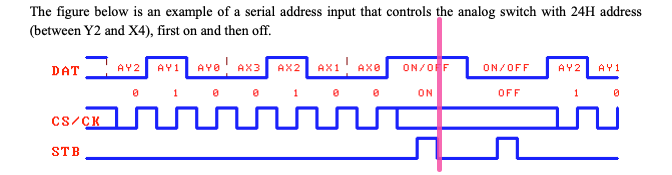
The CH446Qs are basically clones of the MT8816, except for one important difference, they accept serial addressing. The datasheet is kinda vague about how, but it turns out it's just a kinda weird version of SPI.
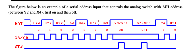
Basically, all the chips see the same data signal, and whichever one sees a pulse on the STB when the last bit comes in will connect or disconnect the selected X and Y inputs. The state of the DAT line when the Strobe comes in determines whether it's connecting or disconnecting. That stretched out clock line shows that it doesn't care about real time, which comes in handy.
PIO State Machine
So I have to do something that's kinda like SPI but not quite, this looks like a job for the RP2040 PIO State Machines.
Even knowing assembly, the learning curve for writing a PIO program is steep. The documentation is really hit-or-miss, the examples are uncommented and written like they're playing code golf, insanely terse. Like these people do realize you can name variables after what they do, right? And these are the Official examples in the datasheet. Anyway after a few days of staring at what looks like gibberish, it starts to click.
I copied the SPI.pio example and edited it from there. Let me try to explain some of the things I learned to hopefully make it easier for you to write a PIO program in the future.
I'm just compiling this with the online pioasm compiler and then pasting the compiled code into spi.pio.h
https://wokwi.com/tools/pioasm
Here's where we are:
;this is basically spi but it sets a system IRQ on the last bit to allow the chip select pulse to happen


.program spi_ch446_multi_cs
.side_set 1

.wrap_target
bitloop:

    out pins, 1        side 0x0 [2]

    nop                side 0x1 [2]

    jmp x-- bitloop    side 0x1

    out pins, 1        side 0x1

    mov x, y           side 0x1

    irq  0             side 0x1

    wait 0 irq 0 rel   side 0x1

    jmp !osre bitloop  side 0x0

public entry_point:                 ; Must set X,Y to n-2 before starting!


    pull ifempty       side 0x0 [1] ; Block with CSn high (minimum 2 cycles)

    nop                side 0x0 [1]; CSn front porch


.wrap
What wasn't explained well is what the hell a sideset pin is. Basically you do your normal-ish assembly code on the left, and then each operation also affects the sideset pin on the right. It's kind of a hack to allow you to control 2 pins in a single clock cycle. In this case, the sideset pin is attached to the CLK, and pins, 1 is DAT.
So, whats going on is that in the regular code, I'm sending a byte to the sm register with this line
pio_sm_put(pio, sm, chAddress);
(the last bit of chAddress is set to 1 or 0 depending if I want to connect or disconnect)
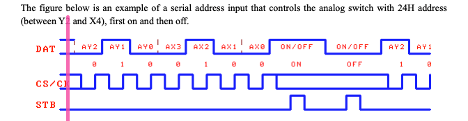
and that pull ifempty will pull in a byte to the working register and send it out one bit at a time while toggling the clock. When it's out of data to send, it triggers a system interrupt request that can be seen outside of the PIO state machine and I deal with it in an ISR in CH446Q.cpp
At this point, here's where we are in the timing diagram:
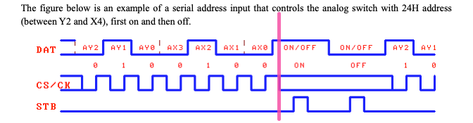
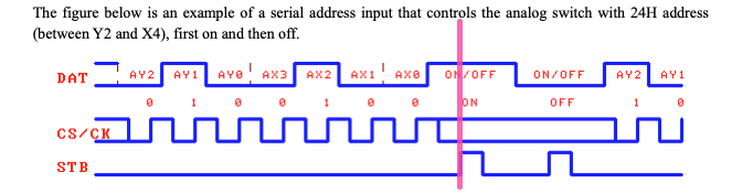
Now we need to select the correct CS line to make the right chip make the connection
void isrFromPio(void)
{
  switch (chipSelect)
  {
  case CHIP_A:
  {
    digitalWriteFast(CS_A, HIGH);
    break;
  }
  case CHIP_B:
  {
    digitalWriteFast(CS_B, HIGH);
    break;
  }
  case CHIP_C:
  {
    digitalWriteFast(CS_C, HIGH);
    break;
  }
  case CHIP_D:
  {
    digitalWriteFast(CS_D, HIGH);
    break;
  }
  case CHIP_E:
  {
    digitalWriteFast(CS_E, HIGH);
    break;
  }
  case CHIP_F:
  {
    digitalWriteFast(CS_F, HIGH);
    break;
  }
  case CHIP_G:
  {
    digitalWriteFast(CS_G, HIGH);
    break;
  }
  case CHIP_H:
  {
    digitalWriteFast(CS_H, HIGH);
    break;
  }
  case CHIP_I:
  {
    digitalWriteFast(CS_I, HIGH);
    break;
  }
  case CHIP_J:
  {
    digitalWriteFast(CS_J, HIGH);
    break;
  }
  case CHIP_K:
  {
    digitalWriteFast(CS_K, HIGH);
    break;
  }
  case CHIP_L:
  {
    digitalWriteFast(CS_L, HIGH);
    break;
  }
  }
delayMicroseconds(1);
  digitalWriteFast(CS_A, LOW);
  digitalWriteFast(CS_B, LOW);
  digitalWriteFast(CS_C, LOW);
  digitalWriteFast(CS_D, LOW);
  digitalWriteFast(CS_E, LOW);
  digitalWriteFast(CS_F, LOW);
  digitalWriteFast(CS_G, LOW);

  digitalWriteFast(CS_H, LOW);
  digitalWriteFast(CS_I, LOW);
  digitalWriteFast(CS_J, LOW);
  digitalWriteFast(CS_K, LOW);
  digitalWriteFast(CS_L, LOW);

  irq_flags = pio0_hw->irq;
  pio_interrupt_clear(pio, PIO0_IRQ_0);
  hw_clear_bits(&pio0_hw->irq, irq_flags);//clears the IRQ

}
The reason I had to do it in an external interrupt instead of in the PIO code is because there's a limit to how many pins can be attached to a single state machine, 8. And this is just way easier to do.
The C
This all runs on the second core just so it can stay somewhat timing sensitive while not worrying about what's going on elsewhere. How this process is triggered is that when the pathfinding algorithm is finished running in core 0, it sets
volatile int sendAllPathsCore2 = 1; // this signals the core 2 to send all the paths to the CH446Q
Then in loop1, is just constantly checks if that's a 1 and will send the paths and set it back to 0. Just a reminder that the cores on an RP2040 share global variables, because it's very useful.
Here's what the SendAllPaths() functions look like.
void sendAllPaths(void) // should we sort them by chip? for now, no
{

  for (int i = 0; i < numberOfPaths; i++)
  {
    sendPath(i, 1);
  }

}

void sendPath(int i, int setOrClear)
{

  uint32_t chAddress = 0;

  int chipToConnect = 0;
  int chYdata = 0;
  int chXdata = 0;

  for (int chip = 0; chip < 4; chip++)
  {
    if (path[i].chip[chip] != -1)
    {
      chipSelect = path[i].chip[chip];

      chipToConnect = path[i].chip[chip];

        chYdata = path[i].y[chip];
        chXdata = path[i].x[chip];

        chYdata = chYdata << 5;
        chYdata = chYdata & 0b11100000;

        chXdata = chXdata << 1;
        chXdata = chXdata & 0b00011110;

        chAddress = chYdata | chXdata;

        if (setOrClear == 1)
        {
          chAddress = chAddress | 0b00000001; // this last bit determines whether we set or unset the path
        }

        chAddress = chAddress << 24;

        // delayMicroseconds(50);

        delayMicroseconds(30);

        pio_sm_put(pio, sm, chAddress);

        delayMicroseconds(40);
      //}
    }
  }
}
The whole process to connect the whole board takes a couple milliseconds at most. But you can shave down these delays if you have some reason to go faster.
Discussions
Become a Hackaday.io Member
Create an account to leave a comment. Already have an account? Log In.