 Ahron Wayne
I'm currently at the lab, shocked that apparently I left this system on for a week while in Tennessee, and trying to go through what's wrong maybe one by one (perhaps more things since I left it on when I'm not sure if the back fans are working properly). I'll probably just add updates to this log throughout the weekend, or if there's any major breakthroughs that will get its own one.
First updates:
So as I said before the safety door interlock is "open". There are 3 switches that can trigger this: One on each left and right access panel, and one in the main door. The one in the main door seems loose and I've tried jiggling and moving that around and will check the electrical connections soon, but first some low hanging fruit:
According to the manual, page 233:
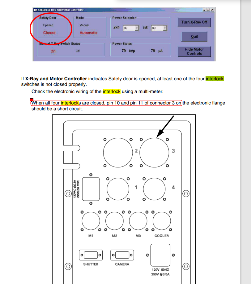
When all interlocks are closed, pins 10 and 11 on connector 3 should be in short circuit. This is not the case (clearly, because it says the interlocks are open). I was hoping that I could just connect them together and it would have the interlock set to "open", but that didn't work. That's probably a "necessary but not sufficient" situation. I also checked the continuity of the cable itself in those pins and it looks good.
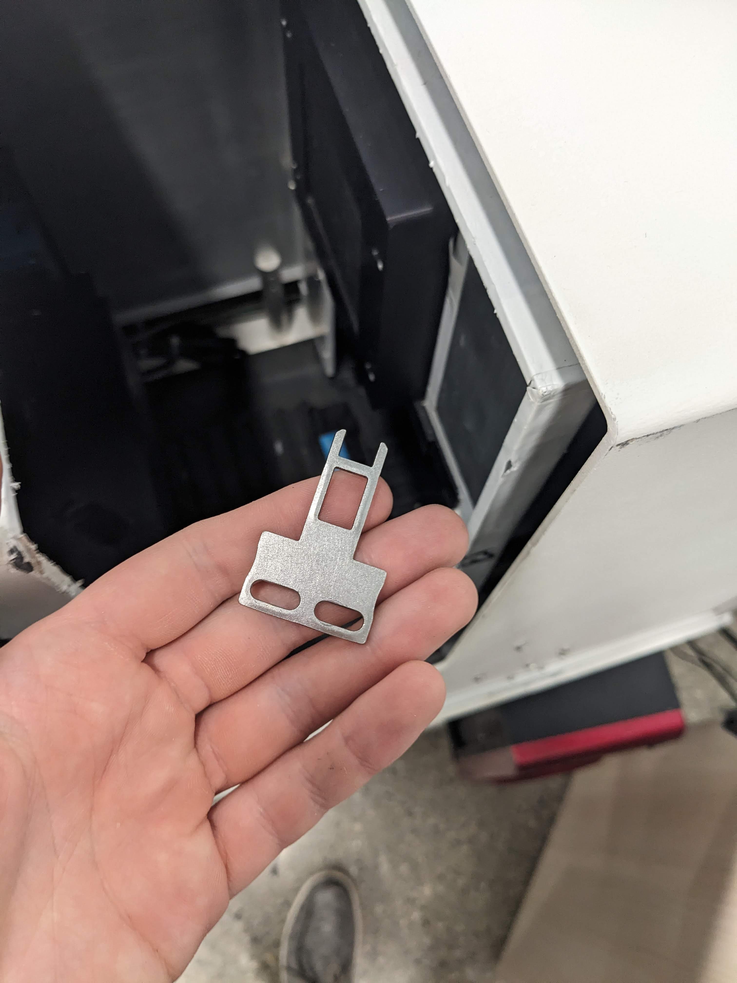
Something that's definitely broken is this little bulb:
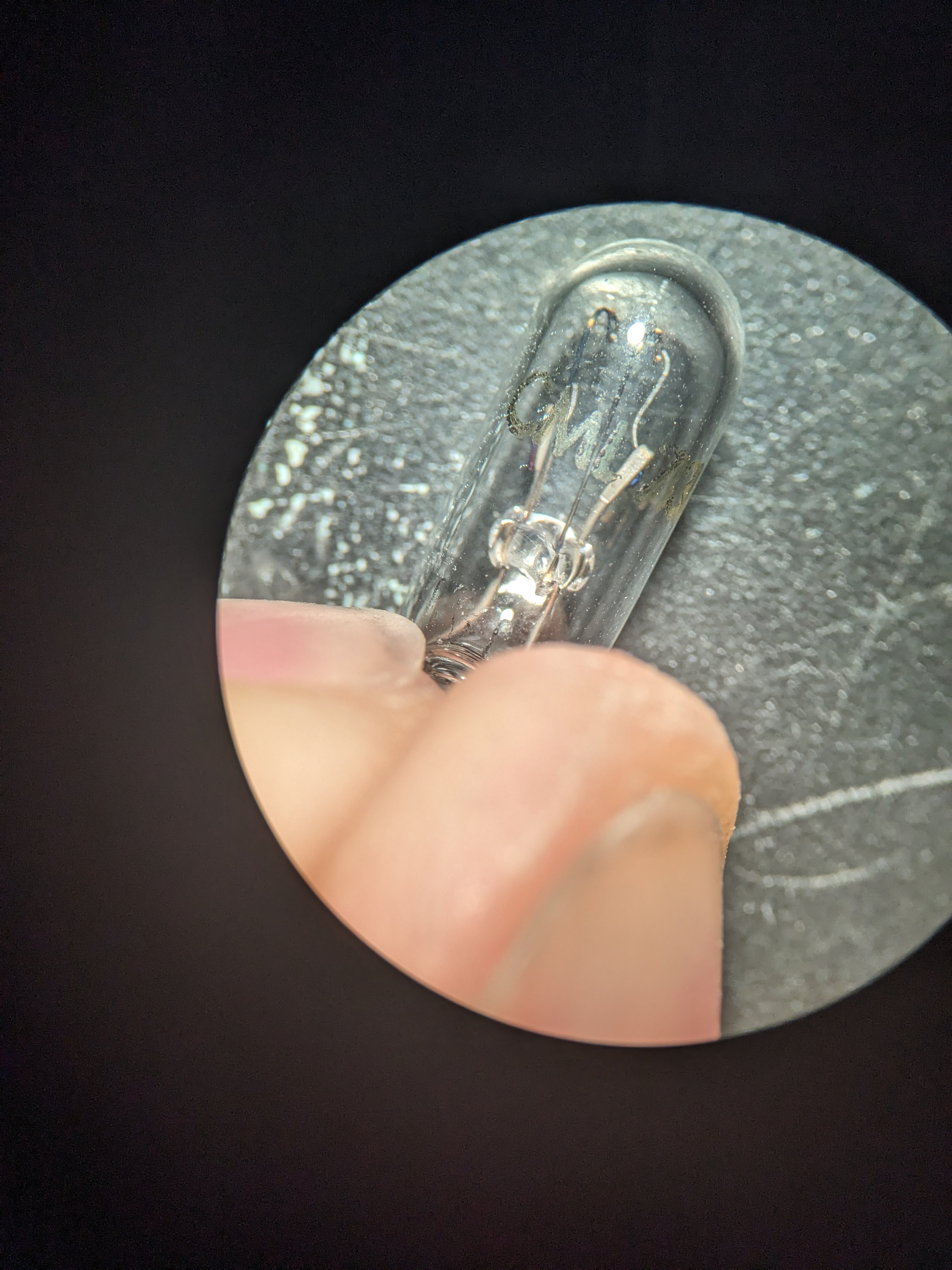
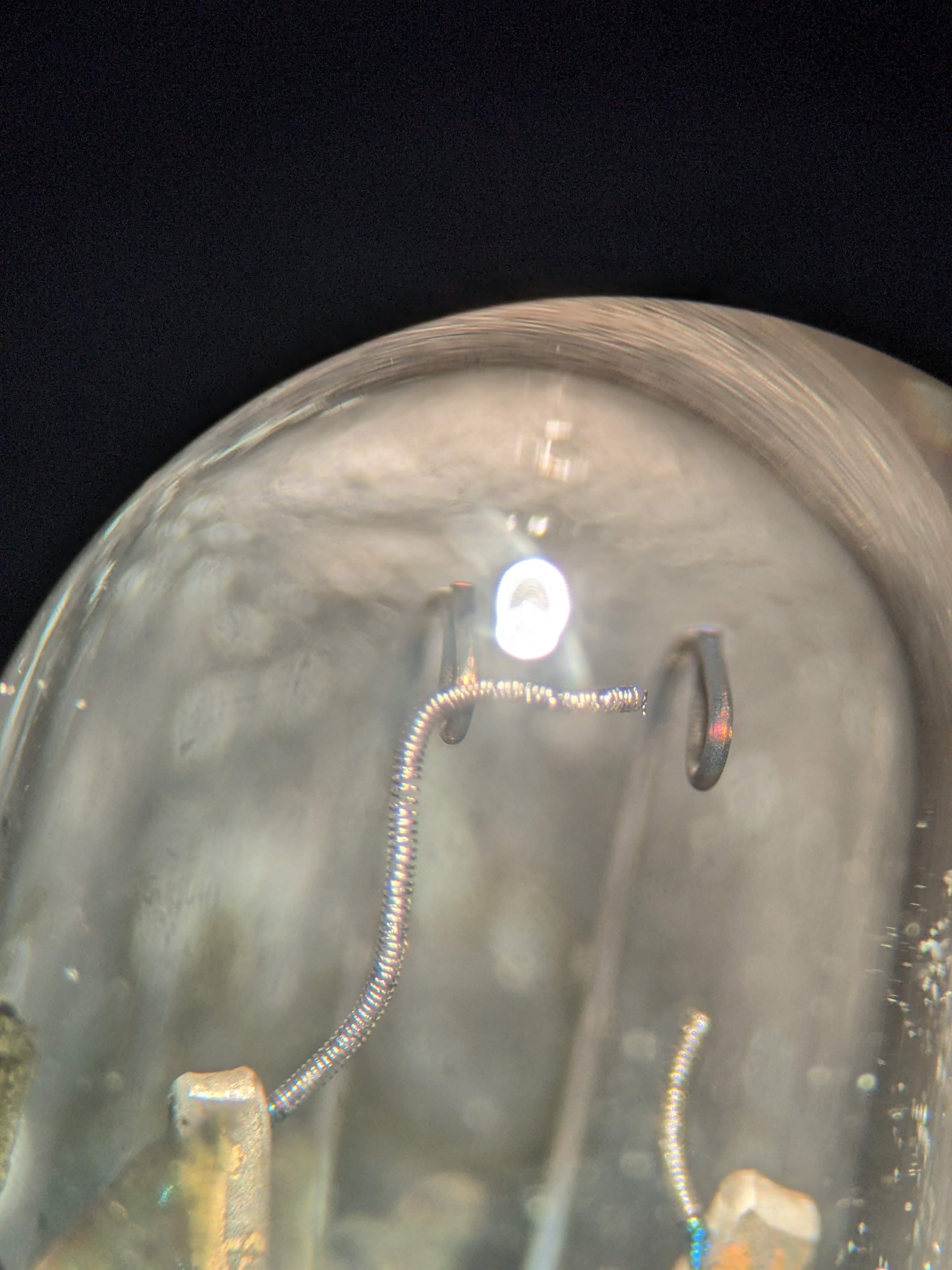
CM73 wedge bulb by CML, not expensive, though I always hate buying things when I need 1 and they only come in packs of 10. This and other clues (the cables actually still being plugged in for instance) make me wonder if the other machine, currently in storage at my amazing friend's house, is perhaps closer to working condition.
The bulb is used to signify whether the controller has just been booted up, and must be reset with a little box. I checked the voltage coming out of the plug and it's 12 volts when the machine powers up --- and should go to 0 when I press the box. That doesn't happen. So it must be tied as well to the door fault.
Update 2: Question/note to self. So there's an additional layer of shielding around the original GE version --- no interlock or anything on that. Currently it's loose and can just be taken off. This was definitely added after manufacturing. Added out of an abundance of caution, or because it was too hard to get the original logos off? (Answer is probably #1, but I know who to ask).
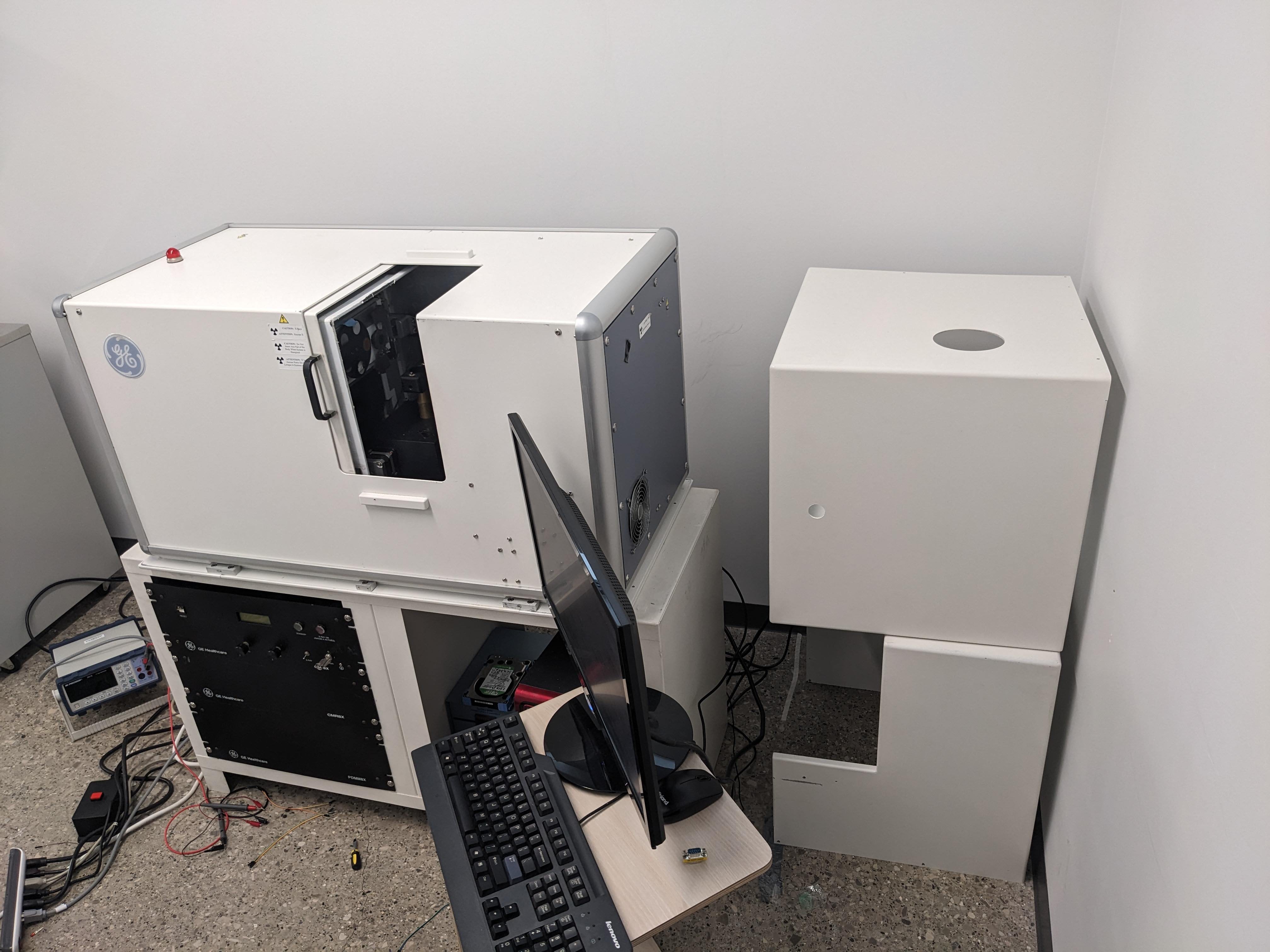
There's also the occasional little lead block scattered around the inside, taped to areas where they had to drill out holes, like where the handle is. If it was peeling off I reattached it with new tape. (something to worry more about after the source actually works during the radiation surveys).
Update 3:
Meanwhile, *this* one says that there are three interconnects (other one actually said 4) and I should be checking connector 2, not 3? That ambiguity isn't great. In any case, connector 2 DOES have pins 10 and 11 in short circuit, despite the door saying "open" (when it's actually closed), and is NOT in short circuit when the door is physically closed. Pin 11 and Pin 13 on Cable 1 (connected to just the door switch) is also correctly short circuit when the door is physically closed. Progress! This means that none of the three interlocks on door and 2 access panels are the problem.
So there must be that 4th interlock or switch that is not connected and leading to pins 10 and 11 on connector 3 that is the problem. On closer inspection, I see that the door actually does have two switches.
Update 4:
Let's walk through this:
Connector 3, pins 10 and 11 being shorted indicates "all 4" interrupts are closed. Never happens.
Connector 2, pins 10 and 11 indicate "all 3" interrupts are closed". Happens if door is closed.
Connector 1, pins 11 and 13 indicate "the door interlock" is closed. Happens if door is closed.
The ambiguity I think arise from an upgrade to the system without upgrading the manual.
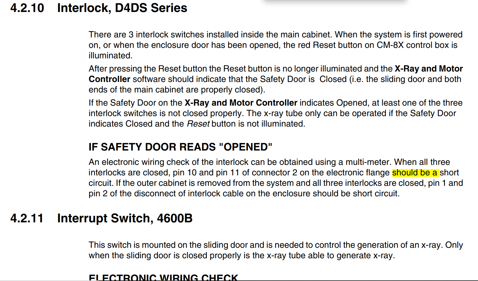
Side panels are on, both of those are good. So the question is: is it the bottom or top switch on the door that is the problem (the "fourth" switch)?
After an annoyingly long unscrewing process (they did not design these things to be serviced without first removing the outer case), I took off the key to the upper switch. So that when the door is closed, only the bottom switch is connected, and I can also plug in the upper key with the door open (bottom switch not closed).
When the door is closed in this state, connector 2 is NOT closed, but connector 1 is. This means that the bottom switch is working and is "the" door switch for connector 1.
And yet, when the door is open, and the key on the top switch is connected, connector 2, indicating that "all three" connectors" are working, is closed.
What the hell? How can both switches be working separately like this? I'm able to close the door and get both connector 2 and 1 to be closed, so it must not actually be a mechanical alignment thing (either door switch) after all?
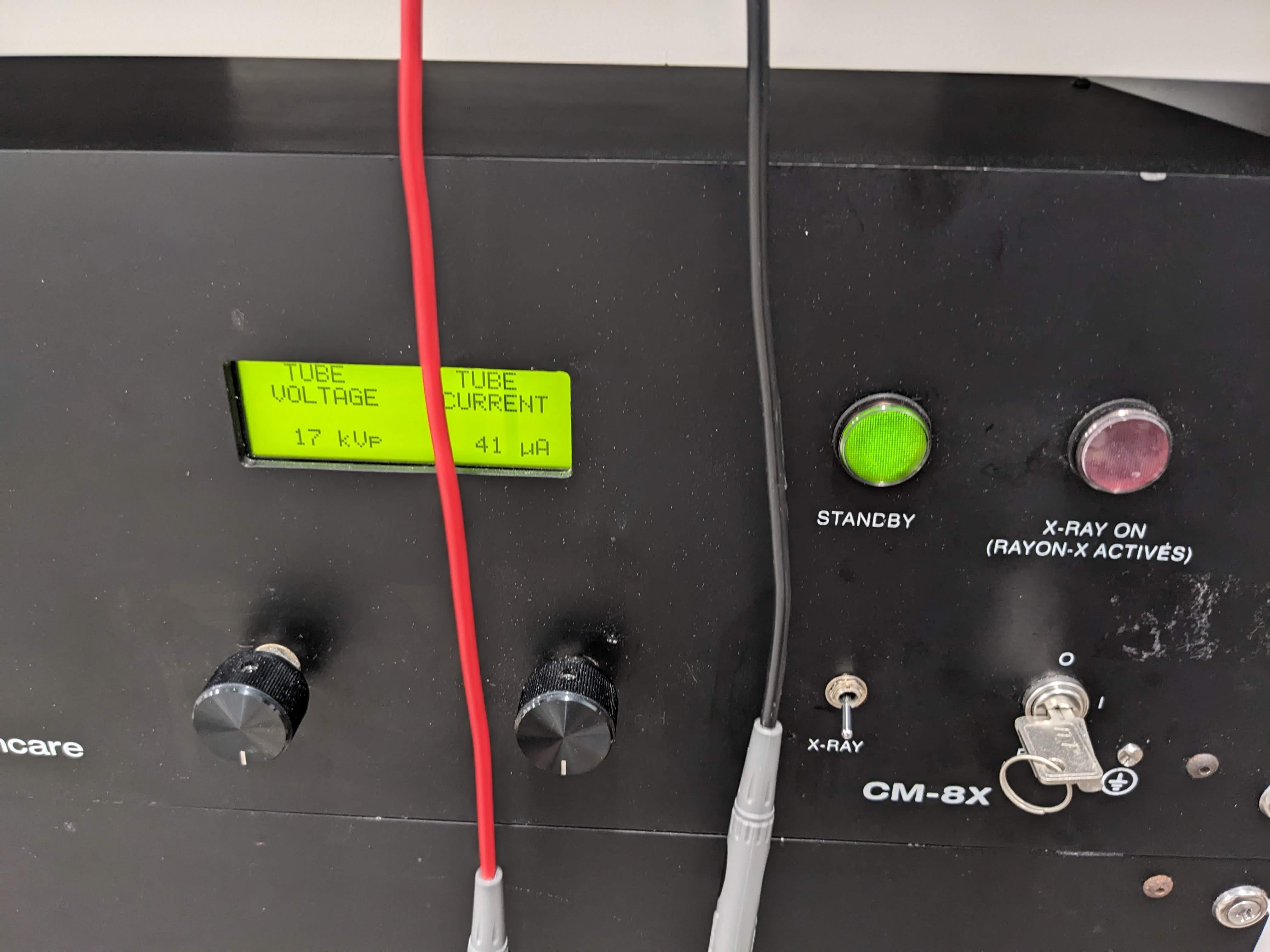
Incidentally, while I was doing this test, I took a look at the x-ray panel and it scared the crap out of me displaying some voltage and current (fluctuating). I closed the door and turned the system off because I don't want to be a Slotin. It was easy to figure out though that it just does that when the cable is disconnected, but it's cool to fantasize!
Discussions
Become a Hackaday.io Member
Create an account to leave a comment. Already have an account? Log In.