 Ahron Wayne
There are many things that are wrong with this machine. This was one of them. I thought it would be easier to fix, but it wasn't. I also thought it would fix all of my problems, but it didn't. Anyway, I haven't been doing nothing these past few weeks --- I've been trying to unwarp the detector. What do I mean by "unwarp"?
Well, modern flat panel X-Ray detector consists of a few main components, but for the sake of this problem there is a scintillator, which converts x-rays into visible light, and then the actual electronic detector, like a CCD, which converts the visible light into an electronic signal:
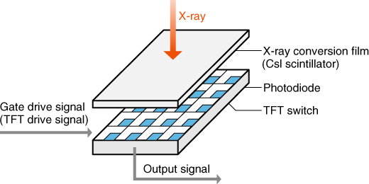
The thing is, this detector is not so modern. Detectors weren't so much bought commercially from Viscom or whatever as they were often assembled as necessary for specific applications. This detector was engineered specifically for CT scanning by coupling a low noise (for the time) CCD to a scintillator plate... and in between those two things, a bundle of thousands of optical fibers. For more on that, see https://hackaday.io/project/191395-x-ray-ct-scanners-get-new-life/log/223337-image-offsets-ancient-scrolls-broken-shutters.
We saw that offset correction work to make the image nice and crisp and remove the pattern and peeling, but it turns out there's also nonlinear warpage at play here --- warpage that is a major source of error unless it's corrected. Originally, it was corrected with a "BB grid" --- Item #2 of the 10 things in this image that I don't actually have:
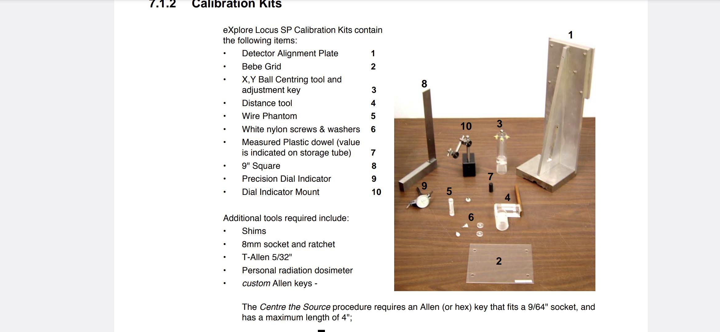
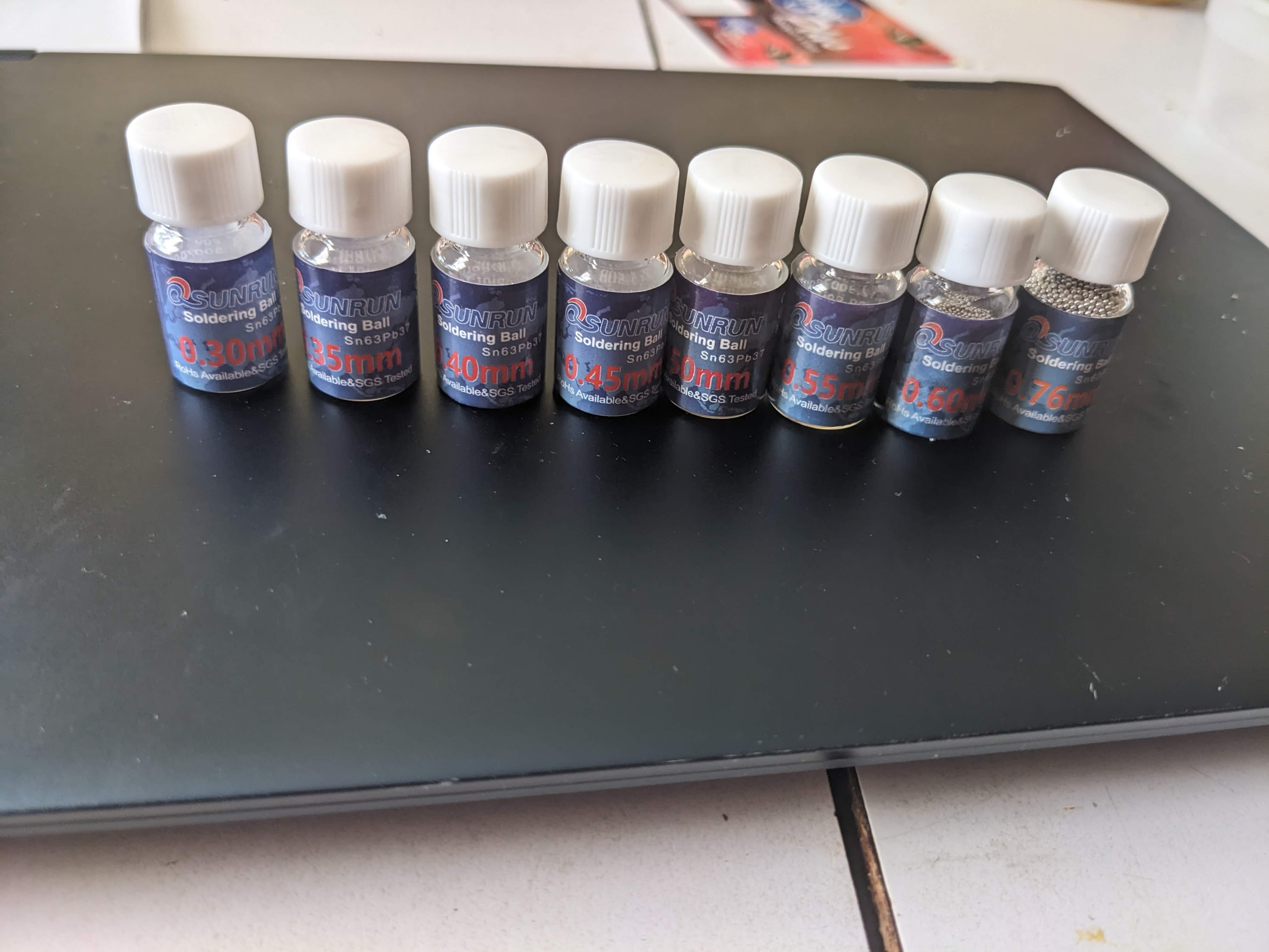
So clearly, I had to make this "BB" grid. It nominally consists of 196 ~0.011 inch tungsten carbide balls spaced out 5mm (love the units), but surely I could fudge this a bit. For instance, I found out that you can get tiny lead balls for cheap for BGA soldering:
Now how to make a relatively precise grid?
Attempt #1: FDM printing didn't go so well on account of the balls are too small.
Attempt #2: SLA printing could produce the holes...
...but the process tends to warp with large flat things.
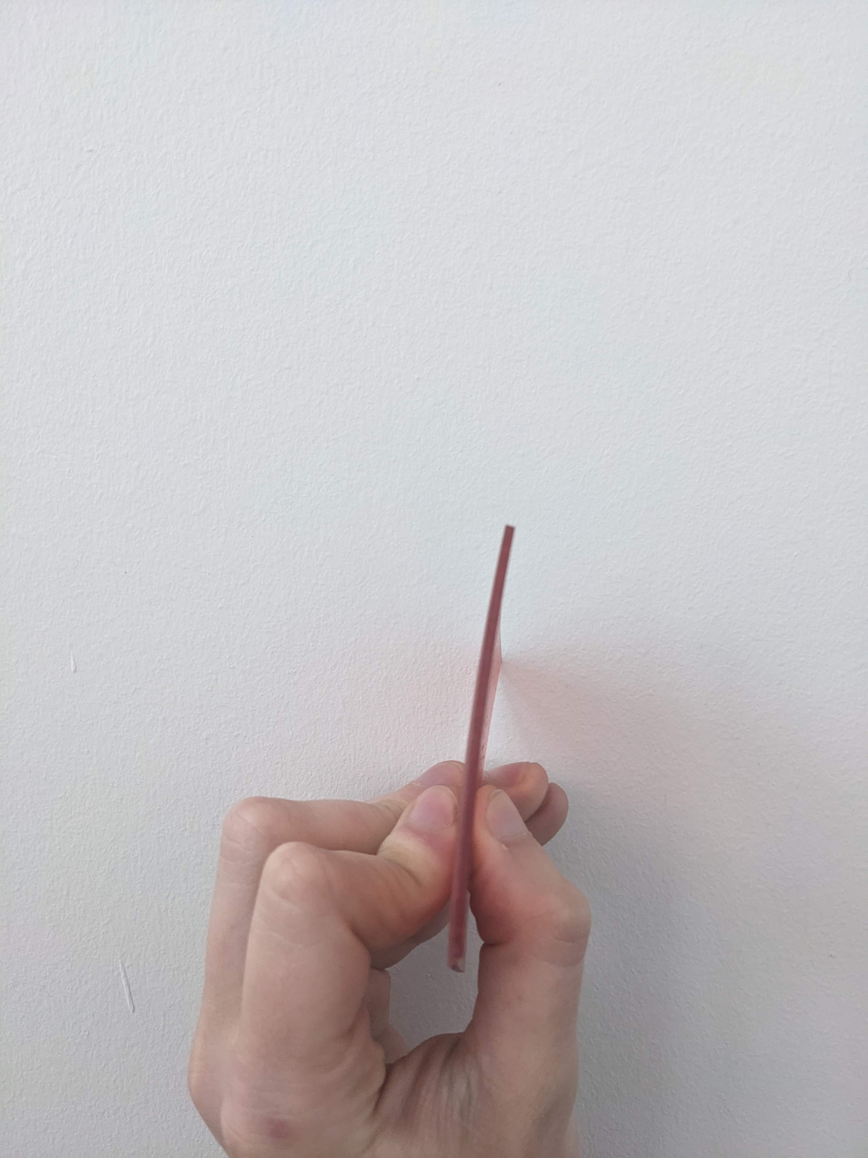
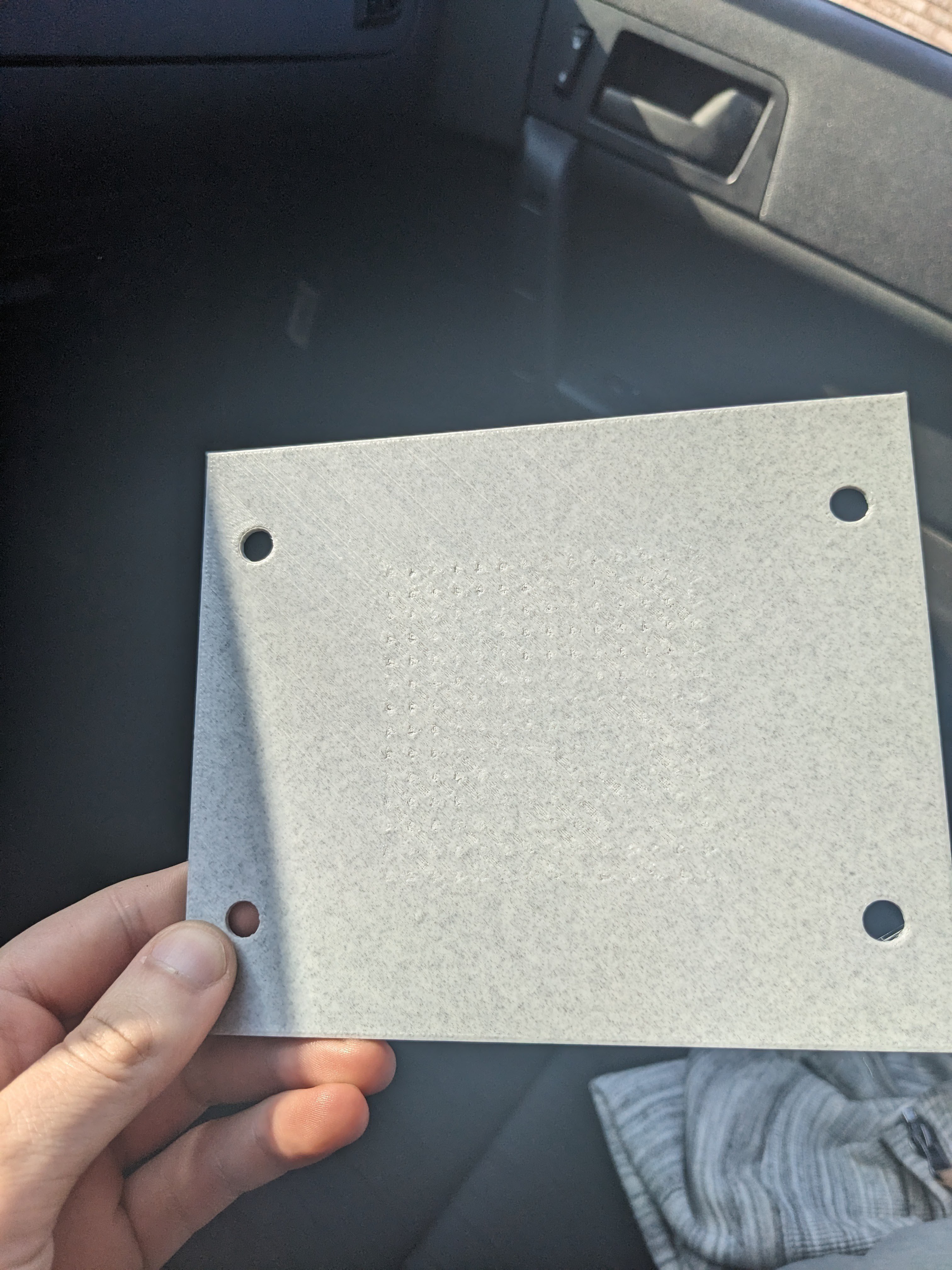
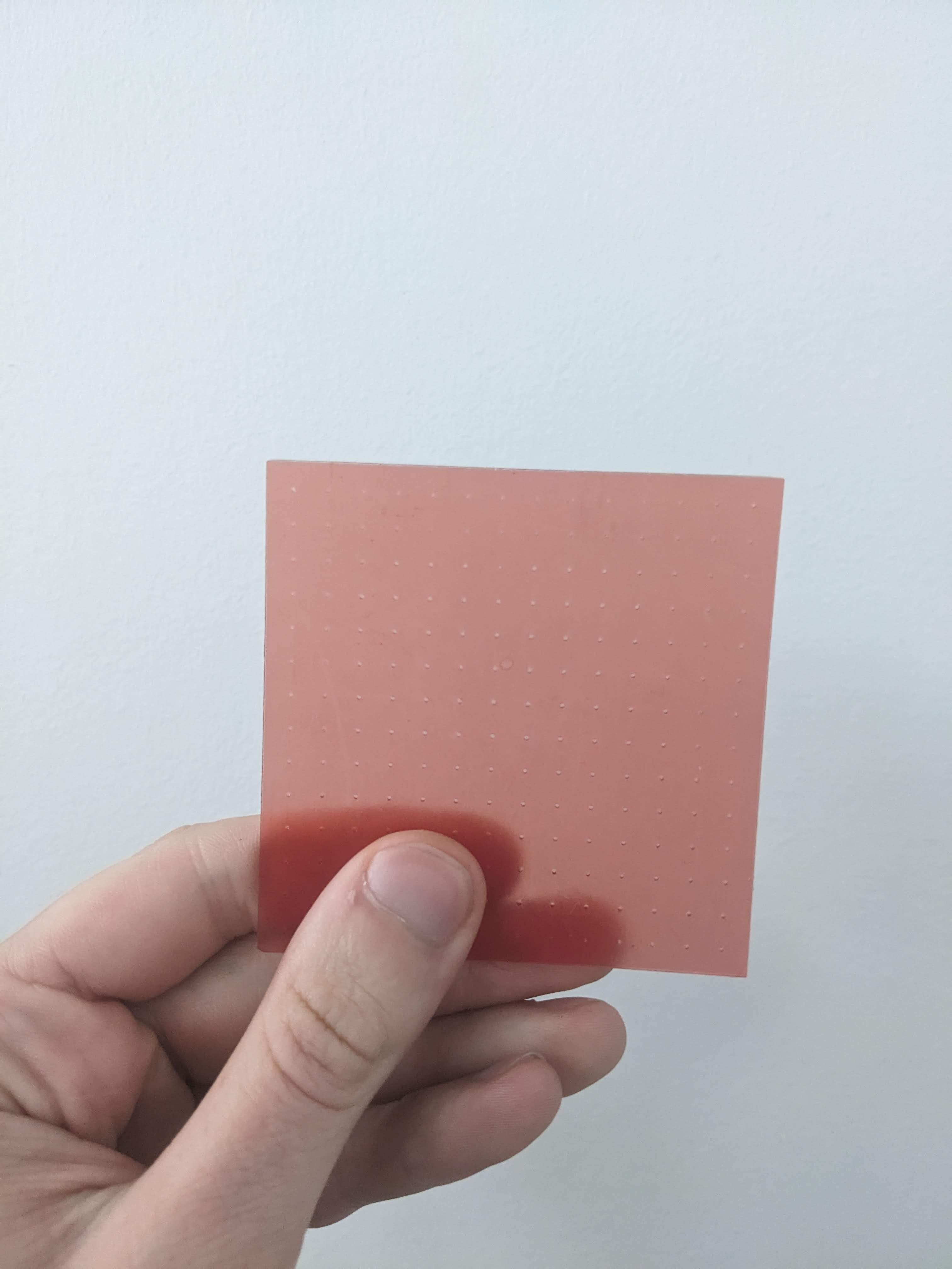
Attempt number THREE, I said, well, maybe I can just laser cut the dang thing out of acrylic. Actually, with a bit of tuning this worked relatively well!
Yes, putting 196 of these in a grid was as laborious as it sounds --- I actually rolled my finger over to get the bulk of them and then inspected and placed individually when needed. It wasn't trivial to make sure just one of the balls was in place either, and then I glued them and taped over for good measure.
There it is on the detector:
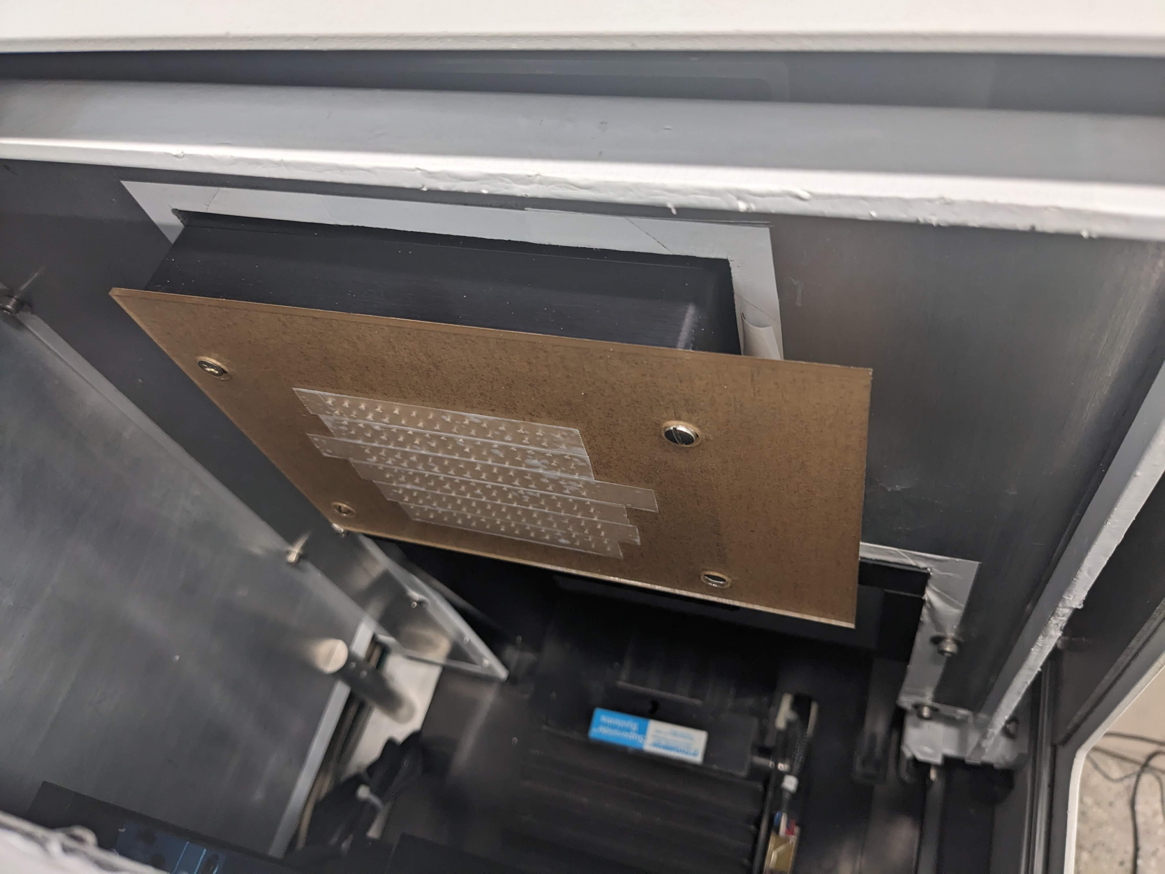
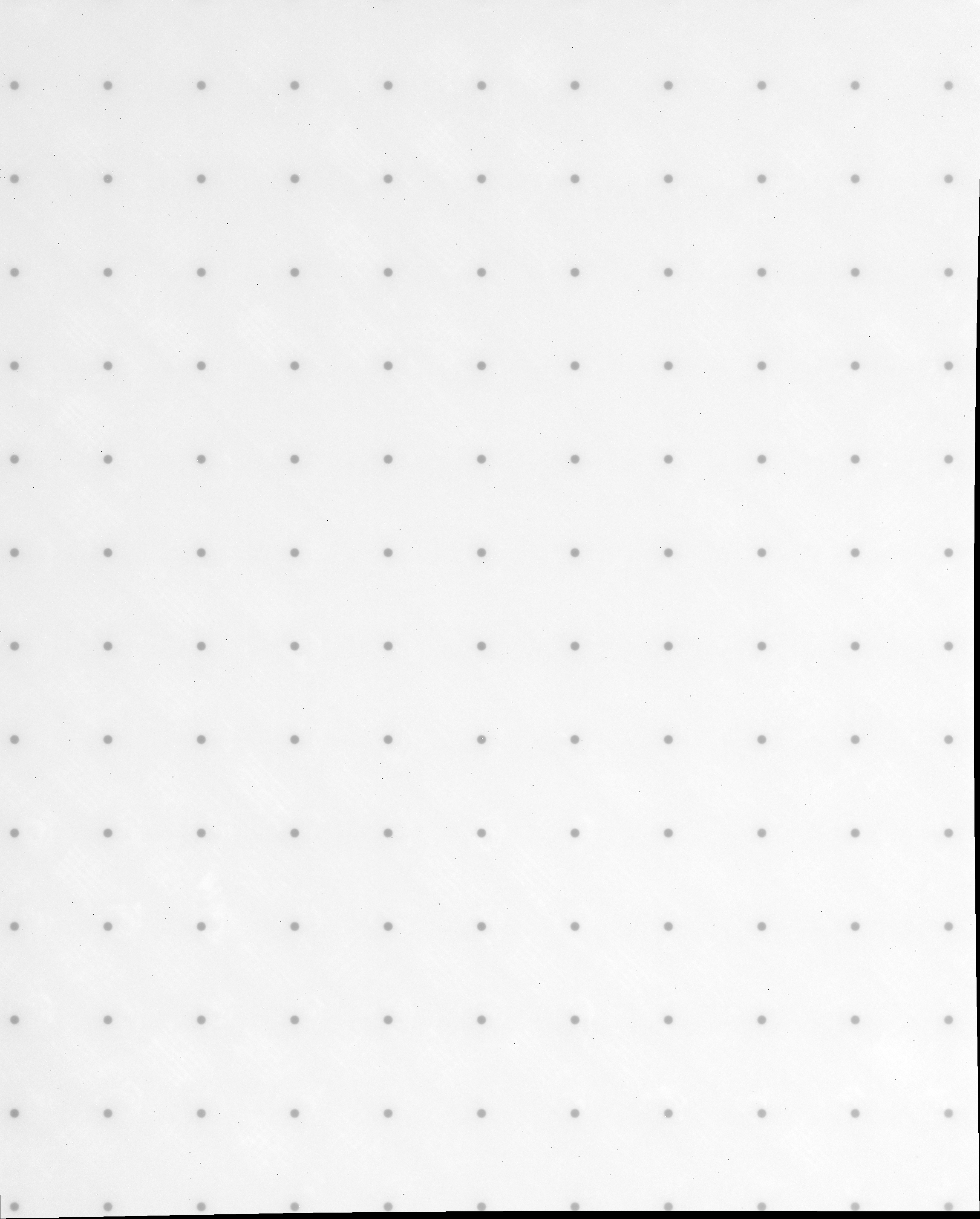
And now we can see what kind of warp we're dealing with!
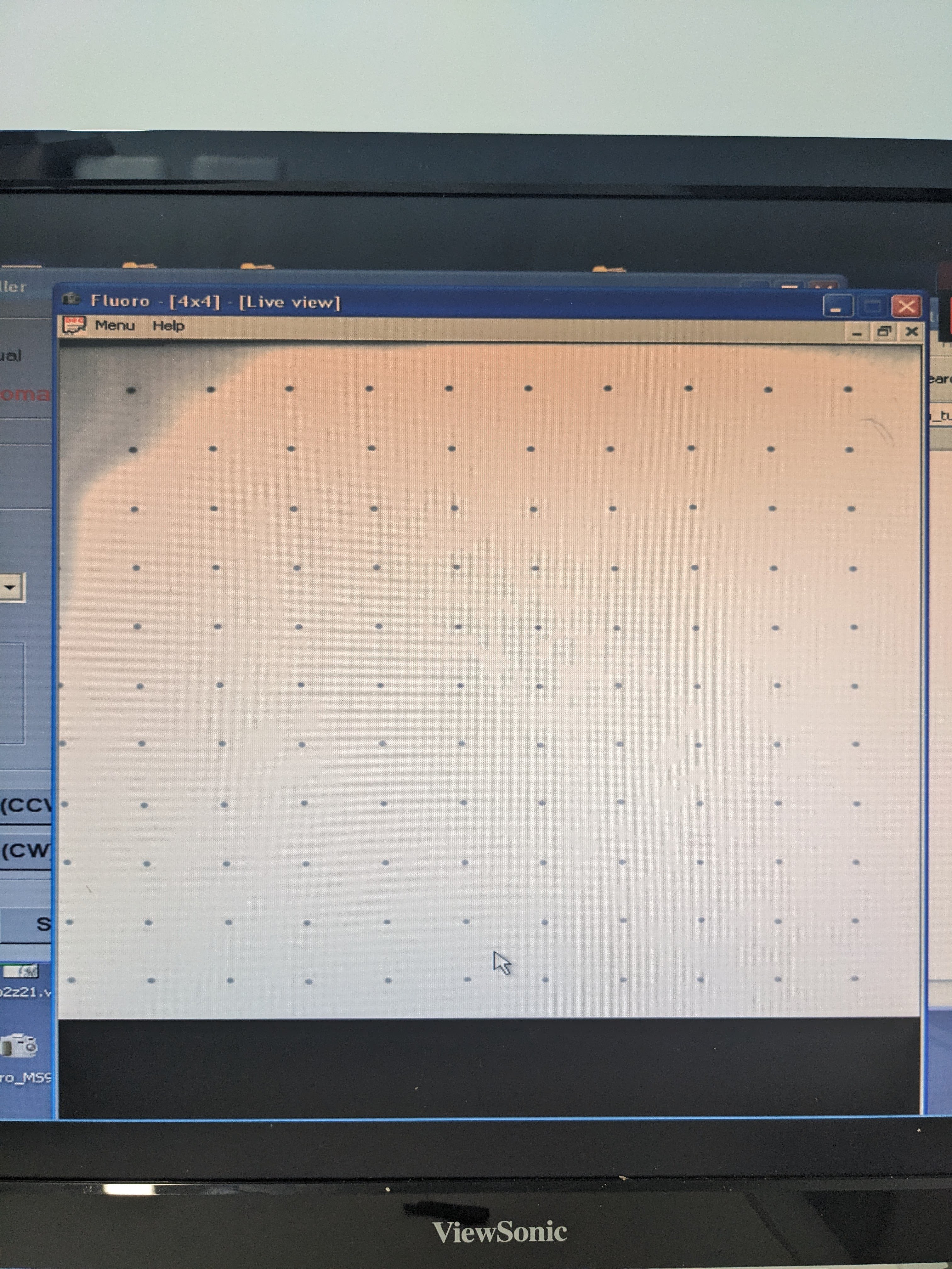
But that's.. hmm. Those balls are crooked. The detector can't be that warped. it's playing tricks with my eyes. The laser cut method is just too imprecise, and I didn't really want to introduce that kind of uncertainty to an already very uncertain calibration process, I thought. So I took the idea of Paul the Original Guy Back at EVS (again) and get a circuit board printed with JLC PCB, with the idea of using the copper pads as targets!
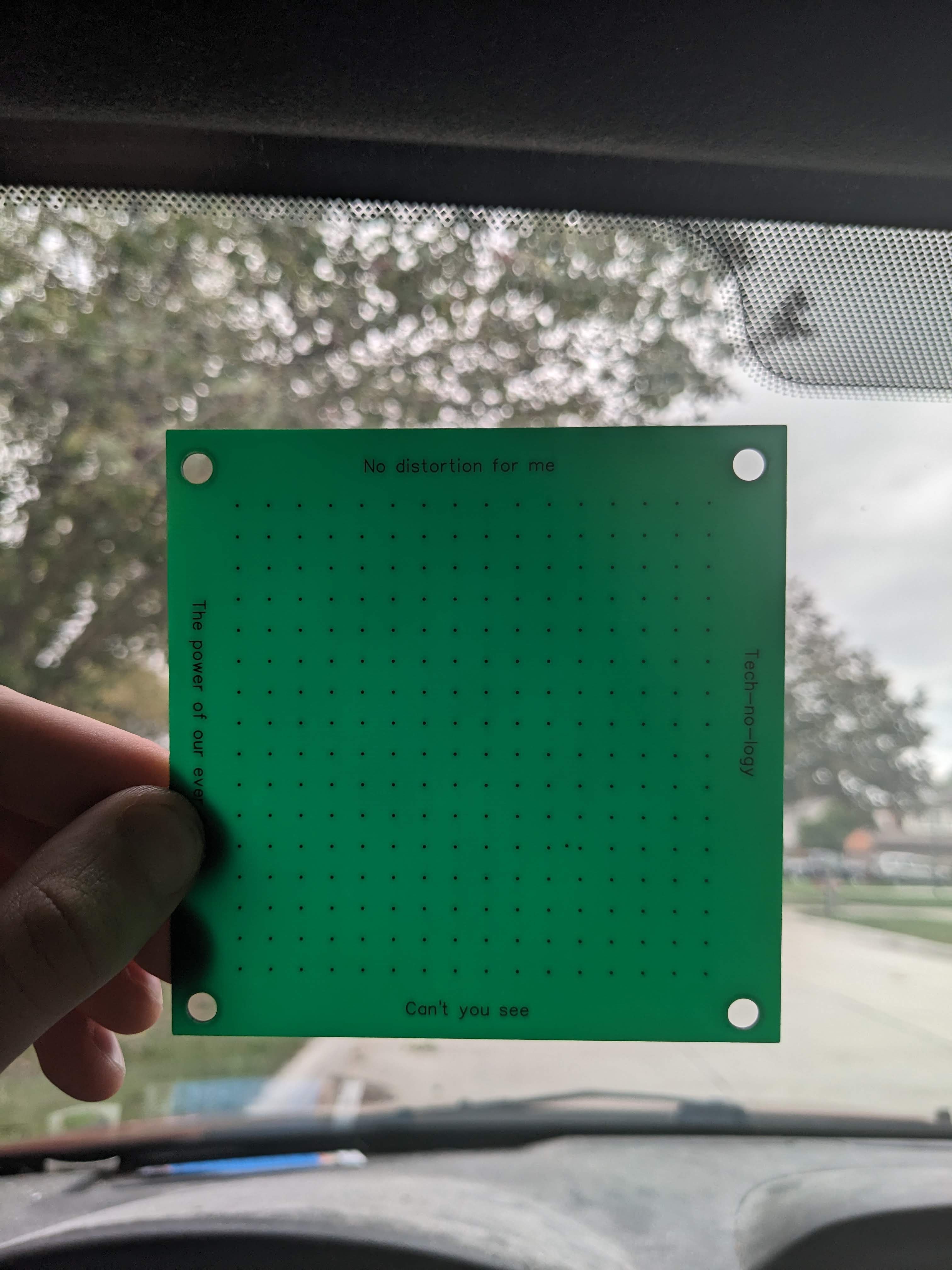
Now this --- save that aggravating misplaced pad you might spot that I had to cut out --- should work accurately, if anything would. (I also used it to determine the "mask" of useful pixels on the detector, incidentally).
This is the "transgen" program:
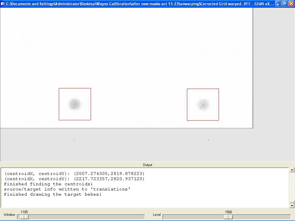
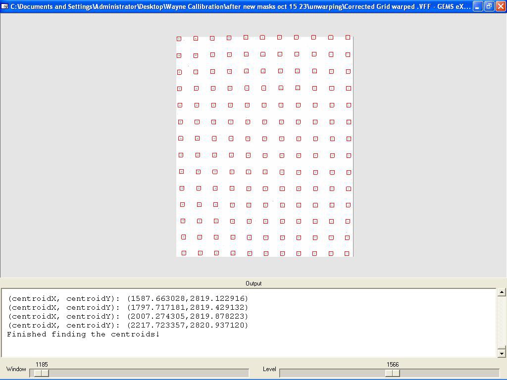
It's kind of cool, once you figure out the parameters that lead to a good search for the red boxes. It took a few tries. But once you do, and all the centroids are located, you get a file that now should hopefully unwarp and make things much more accurate!

And it does! More pats on the back!
I tested it by swapping the old file of a couple of recent scans. The results were, I would say, noticeable but not solving a few specific big artifacts, like rotation center. I've been muttering to myself about this for several days/weeks now, trying to understand what is causing it, and a couple of days ago got a big clue. Next time, we'll be talking about the Parker method.
Discussions
Become a Hackaday.io Member
Create an account to leave a comment. Already have an account? Log In.