 schlion
Before this project, I had never done SMD soldering, maybe bodging a wire onto an ESP8266 ESP-01 module, but that was it. Usually, I'd just try to solder all the tiny components by hand. But the LED that we're using doesn't have contacts on its side, but rather the solder pads are under the chip :/
This calls for a different soldering technique and a learning experience! There are quite a few ways of soldering PCBS from fancy vapor phase soldering, over IR and convention ovens (industrial and DIY), to hot air rework stations and finally the humble hot plate. I did not find a lot of recent articles about reflowing and since my maker space doesn't have a reflow oven and I don't have a rework station, I tried the hot pan/ hot plate reflow technique (https://www.sparkfun.com/tutorials/59), since it was cheap and the former tenants left me with an abundance of old pots.
For applying the solder paste, I also referred to a Sparkfun blog post. Although I did change it up a bit. I only extruded a small amount of paste from the syringe and wiped it over the stencil with a credit card.
Then I started populating the PCBs using tweezers. What really helped me was an interactive Bill of materials. It really helped me keep track of what I had already placed and where. And it's just a simple HTML file.
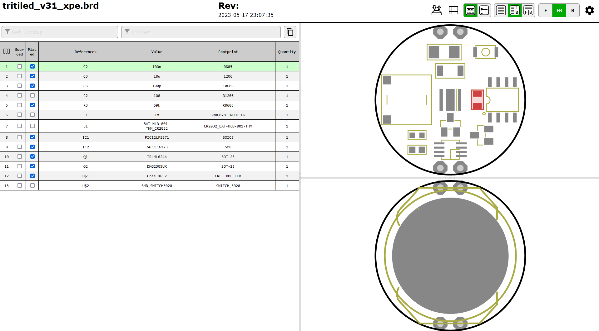
I generated it with the KiCAD Plugin: Interactive HTML BOM, but you can use it in standalone mode, even with EAGLE files. You might need to install some python packages first
pip install wxpython jsonschema
And then you can run
python ./<path>/generate_interactive_bom.py ./tritiled/hardware/eagle/V3/tritiled_v31_xpe.brd
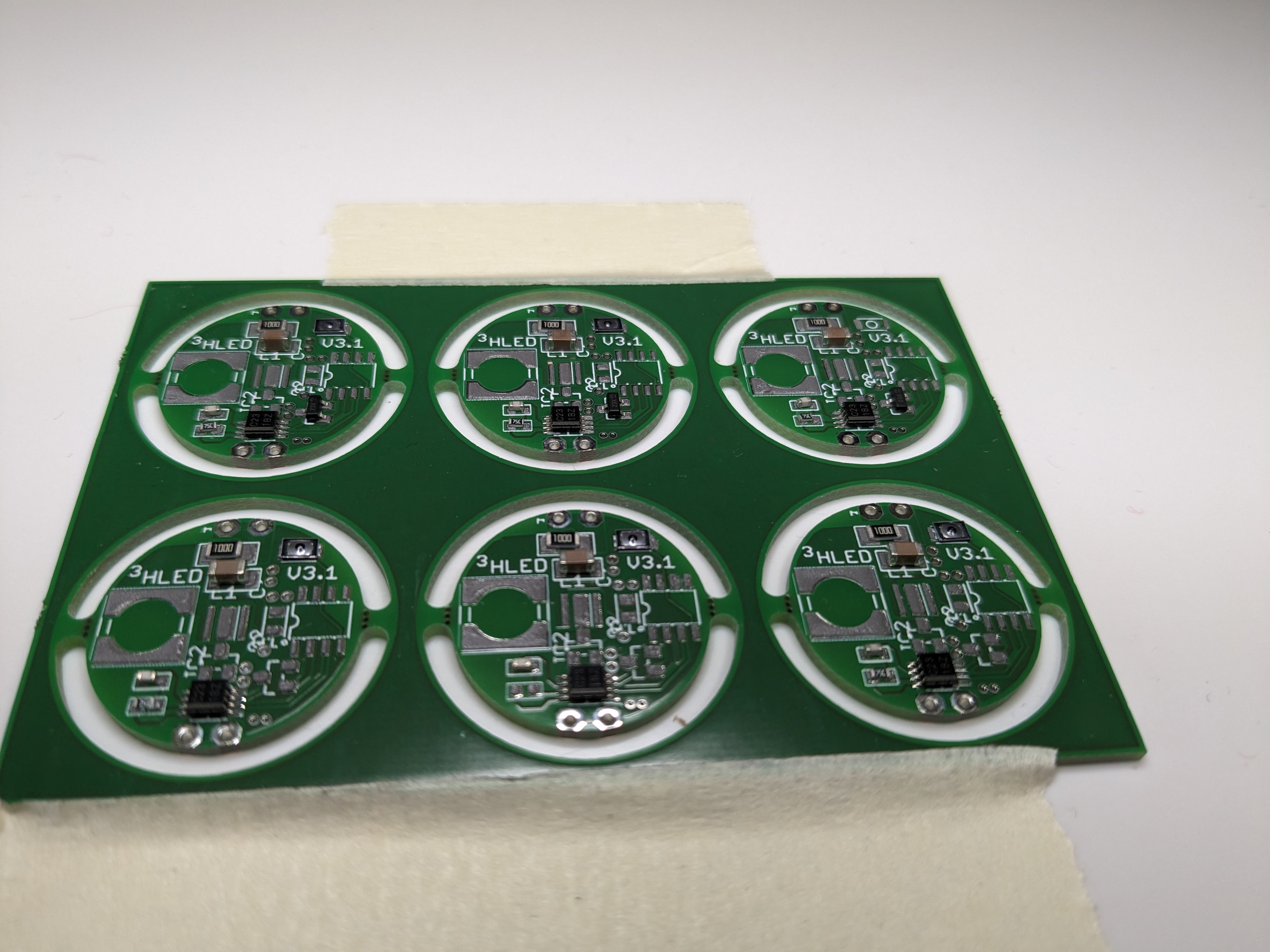
PCB with solder paste and some components.n In the end, I should have tried just making one of these and learn from that, but hindsight is 20/20.
With (ceramic) capacitors and resistors the orientation doesn't matter, but for the LED, and the monostable vibrator and the PIC it really does! The PIC is easy, as there is a dot marking pin 1 and also a dot on the PCB. I double-checked the datasheet anyway and compared it with the board view, after importing the board to KICAD.
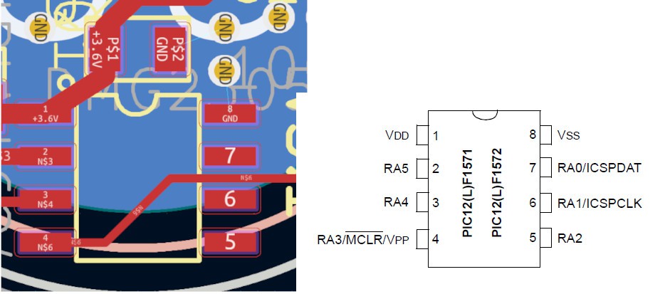
Note: Microchip calls Vcc Vdd and GND Vss.
Same for the monostable. The PIN 1 marker is a grey bar in this case.
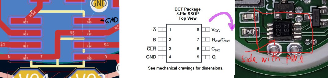
And at last the LED.
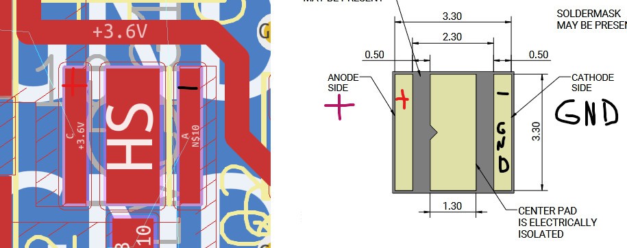
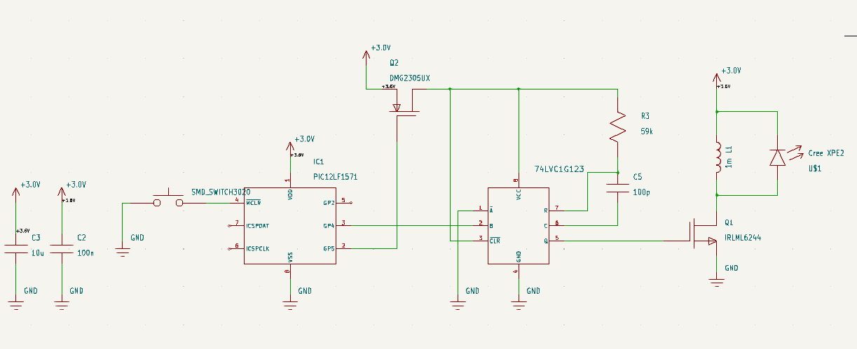
At this point I made a mistake. I put the Anode of the LED to the 3.6V pad. In that moment I had forgotten, that the LED is supposed to act as a flyback diode. That's the whole point! Had I checked the schematic I might have avoid making this mistake six times in a row.
Discussions
Become a Hackaday.io Member
Create an account to leave a comment. Already have an account? Log In.