System Overview
The MorseMate ultimately serves as a communication device, allowing users to connect with others using MorseMates. To set up the device, users will connect it to a wireless network and choose a username and password. These credentials will be saved for future use. Once set up, users can begin sending and receiving messages. They can input their messages using the main button and utilize other buttons for actions like sending the message, reading the latest inbound message, editing their typed message, or changing the contact for communication.
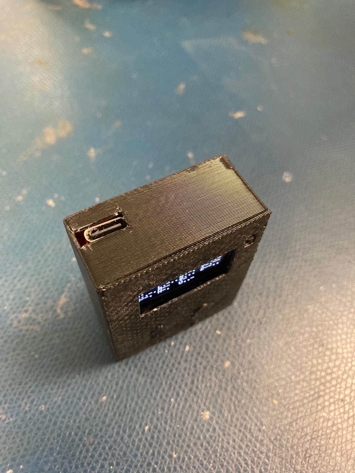
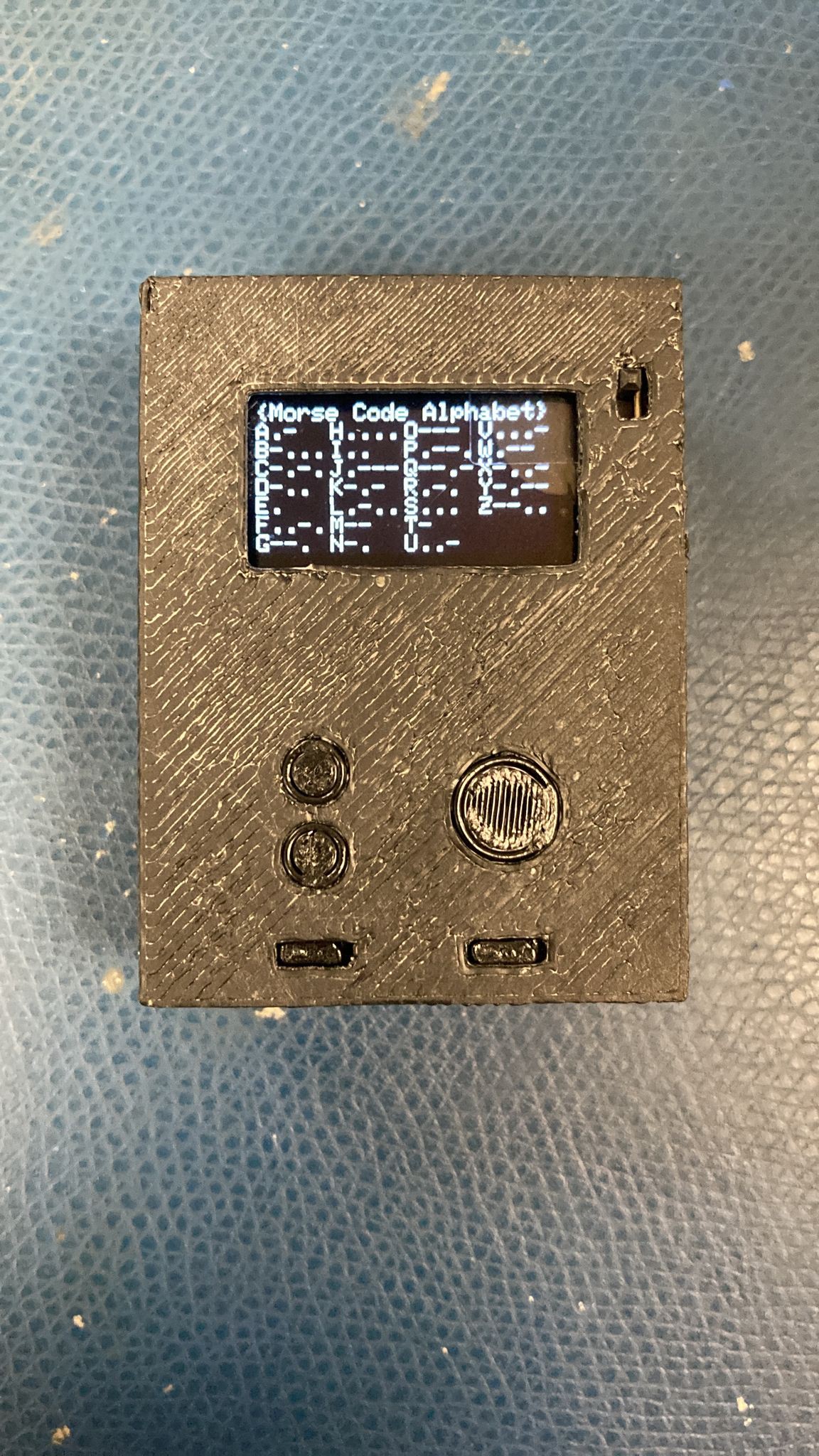
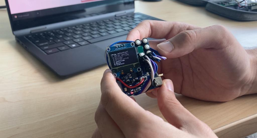
The external design of our product features several key components. It includes a series of buttons, including a prominent main button designed for discrete input of Morse code, allowing easy manipulation even from within a pocket. Additionally, a small OLED display provides information to the user when the device is not in a pocket.
Internally, the MorseMate is powered by a rechargeable battery. At the core of the system is an ESP32 module, enabling WiFi functionality and handling other system components. Furthermore, a small vibration motor discreetly notifies users of incoming messages by vibrating in Morse code patterns.
In the digital realm, our product utilizes MQTT for sending and receiving messages. Messages are posted to an MQTT topic named after the intended recipient's username. Each device is subscribed to its own username topic, ensuring messages reach the intended recipient. This flexibility allows for future expansion, such as incorporating clients on other devices like web browsers.
Block Diagram: Communication Diagram

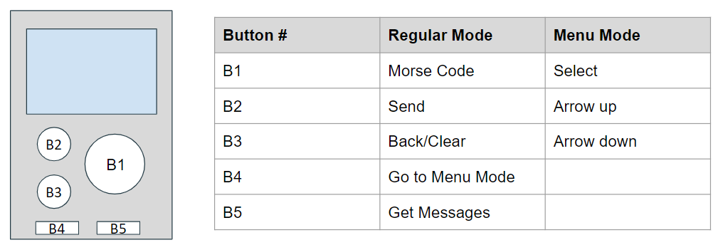
Block Diagram: Button Layout
Algorithms and Code
The development of our firmware was greatly facilitated by using the Arduino programming language, which provided us with a robust and user-friendly platform for prototyping and developing the MorseMate. With its simplified environment and extensive library, Arduino allowed us to seamlessly interface with the ESP32 and implement essential features, including WiFi connectivity and provisioning mode, MQTT communication, OLED screen interaction, and Morse code translation. Our code can be divided into four distinct segments, each responsible for specific functionalities within our project.
1) Configuration Management and WiFi Connection Setup:
The first segment of the code manages the device's configuration using WiFiManager and handles the loading and saving of configuration settings to a JSON file, as seen in the code excerpt below. It also includes the parsing of user-defined contacts. The goal of this segment was to provide a simplified interface for users to input their desired settings and to ensure that the configuration was stored and retrieved correctly.
2) MQTT Communication:
This portion of the code establishes an MQTT connection with a specified broker, subscribes to a specific topic, and handles incoming messages through a callback function. It also provides functions for sending MQTT messages. This enabled communication between the ESP32 device and the MQTT broker, facilitating the exchange of messages between users.
3) Morse Code Generation and Vibration Control:
This segment is responsible for generating Morse code patterns based on input characters and controlling a vibration motor to produce the corresponding Morse code signals. It provides functions for buzzing individual letters, buzzing entire words, and generating notification signals, enhancing the user experience with tactile feedback. In order to ensure consistency and avoid potential errors caused by mistyped messages, a decision was made to prioritize standardization in the Morse code generation and vibration control segment. Instead of relying on live vibrations triggered by each user input, predefined Morse code patterns are generated for each character. This approach minimizes the risk of accidental vibrations due to input errors or variations. This standardization can be seen in the code snippet below.
4) Mode Selection and User Interface:
This segment allows users to navigate through different modes and interact with the OLED screen, as opposed to simply sending and receiving messages. It includes a menu loop that displays a menu of available modes on the screen and allows users to select a desired mode. It also incorporates other loops for specific modes such as contact selection, Morse code decoding, provisioning mode, settings adjustment (volume, speed, etc.), and checking previous messages that may have been missed. Figure 1 shows the mode selection menu on the OLED as seen by the user.

Overall, the Arduino code provides the essential functionality for the MorseMate, enabling users to navigate through different modes, interact with the OLED screen, adjust settings, and communicate via Morse code.
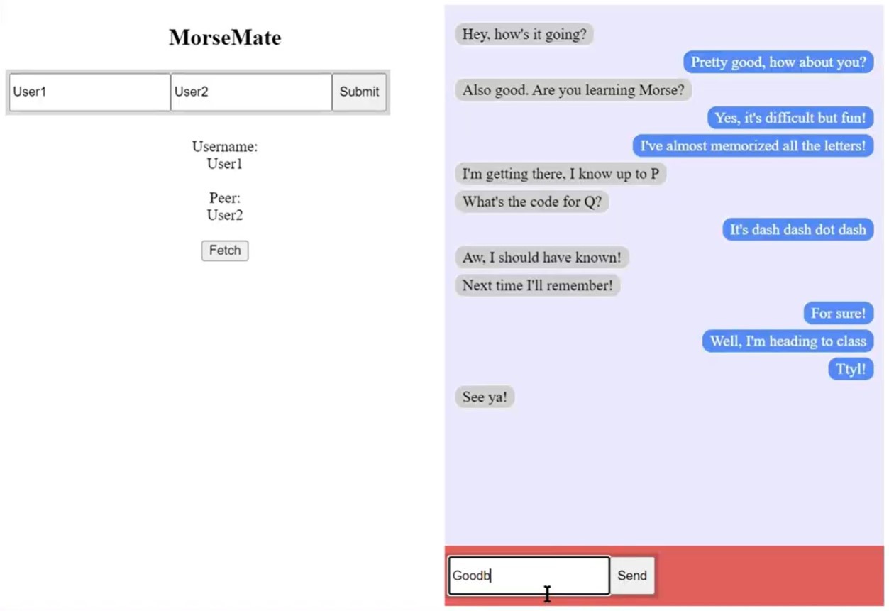
Furthermore, our project incorporates a robust server code. Developed using Node.js, the server is used to facilitate communication and interaction between users and the device. It serves as a central component that allows users to interface with the device through a website. The server receives input from users, such as typed messages or requests to fetch text files, and handles these requests by publishing them to the MQTT broker, which in turn triggers actions on the device. The server also receives and processes messages from the device, such as incoming messages to be saved or routed, and relays the appropriate information back to the users through the website interface.
PCB
The PCB design for our project underwent several iterations before reaching our final board. Key features included Schottky diodes on power input lines (VIN, VBAT, VBUS), to protect against power surges; a DC vibration motor circuit, enabling precise control over vibration signals. To facilitate programming and debugging, we incorporated a 24-pin USB-UART module, which also allowed for additional automatic IO0/reset circuitry implementation. Additionally, we included a USB-C port on the PCB to allow easy charging for the user, and which coupled with the USB-UART circuitry allowed us to more easily update the firmware of the device. Finally, a battery charging module was integrated to support the rechargeable battery. The compact PCB design was essential in creating a pocketable device that is unobtrusive to everyday life while enabling discrete communication when needed.
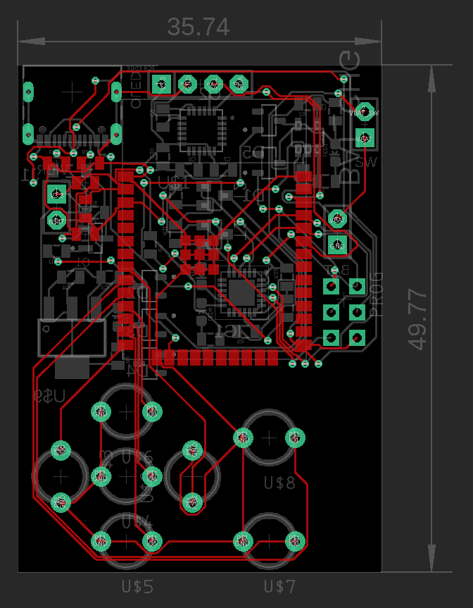
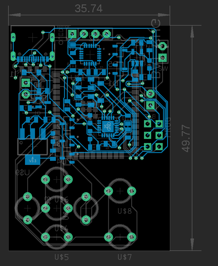
PCB for Final Prototype (top view, back view)
3D Printing
When designing the enclosure for our device, we prioritized user-friendliness and ease of use. Our primary objective was to create a 3D printable model that offered a seamless and intuitive experience for users. We paid special attention to ensure convenient access to the screen and charging port. A major focus was also placed on optimizing the layout of the buttons, aiming for an intuitive and straightforward user experience. To achieve this, we experimented with various button sizes and shapes, carefully refining the design to strike the perfect balance of functionality and usability.
Process
Our team adopted a modular approach in the creation of MorseMate, which encompassed both software and hardware features. Beginning with a breadboard prototype, we deconstructed MorseMate into its fundamental components, including the DC vibration motor circuit and initial ESP programming. One pivotal aspect was the implementation of Morse code translation, converting sequences of dots and dashes input by a user into corresponding letters. We also developed a standardized Morse code output using the vibration DC motor. Our initial iteration featured a button interface for inputting Morse code, with translations displayed on an OLED screen.

Thereafter, we delved into establishing a communication protocol by implementing basic MQTT functionality between the ESP32 and MQTTX. Once we successfully achieved Morse code translation, we conducted thorough testing to ensure transmission of Morse code inputs to a specified MQTT broker via MQTTX. With the confidence in our modular components, we proceeded to create the first iteration of the PCB. The addition of headers to different modules such as the battery charging module, USB-C port, and vibration motor circuit proved vital in functionality verification and streamlined debugging of potential routing issues.
While awaiting the production of the PCB boards, we focused on designing and implementing the architecture for wireless communication and developing the server code. The server played a crucial role in facilitating user interaction by receiving input such as typed messages or requests to fetch text files. These requests were then published to the MQTT broker, triggering corresponding actions on the device. Additionally, the server processed incoming messages from the device, enabling functionalities such as message storage and routing. The server seamlessly relayed relevant information back to users through our website interface, ensuring smooth and accessible communication.
Recognizing the need for user authentication in a multi-user environment, we implemented a database (text file) to store usernames and passwords securely. This measure guaranteed unique usernames and enhanced security for each user accessing the website interface. Furthermore, we devoted efforts to create wireframes and develop the initial prototype of the website, laying the foundation for an engaging and user-friendly interface.
After successfully soldering and testing our initial PCB, we embarked on creating the final PCB prototype, addressing any connection, symbol, or layout issues we encountered in the first version. As we moved closer to the final design, we recognized the opportunity to enhance the device further. This led us to introduce a mode setting feature, allowing users to access provisioning mode for Wi-Fi setup, toggle the device's "silent mode" to enable or disable the vibration motor, display a Morse code decoder on the screen for translation purposes, and even adjust the speed at which Morse code signals were received, catering to users of varying Morse code proficiency levels.
With the PCB and code integration nearing completion, we soldered the final PCB, as well as combined the Arduino code with the server code. To provide a comprehensive user experience, we designed an enclosure using OnShape and utilized a 3D printer to bring it to life. The enclosure featured essential components such as a fully functional USB-C port for code updates, appropriately sized buttons for different functionalities—a large round button for Morse code input, two smaller buttons for backspace and sending actions, and up and down buttons for easy navigation through the menu and mode options.
All the design iterations, debugging processes, soldering efforts, code integration, and enclosure creation culminated in the creation of the MorseMate device—an elegant and compact solution that seamlessly blends hardware and software. It embodies our vision of discreet and efficient communication, providing users with a versatile and user-friendly tool that can be easily carried and used in various scenarios.