Design Description
Overall, the GRIP consists of sensor inputs sent and processed by the ESP32, and then data sent to the web-server through websockets. The web-server then also pulls the 3D hand models from a github repository based on the sensor input given. It also renders the model’s orientation and rotational movement regularly given data from the sensors. Figure 1 shows a block diagram of the GRIP project.
Figure 1: Block Diagram for the GRIP Project
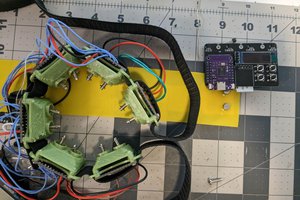
The main sensors used in the GRIP are long flex sensors which are actually potentiometers that change their resistances as they are bent. For these particular sensors, their resistance goes up as they are bent. Figure 2 shows the flex sensors positioned on the individual fingers of a glove.
Figure 2: Flex Sensors on Glove
Since every person’s hand will have different amounts of flex, there is a calibration function to find the minimum and maximum resistance values given a certain person’s hand. Once the individual fingers’ resistances have been calibrated, the ESP32 just takes in the resistance values from each of the sensors. These analog resistances are then digitized into 3 states: 0 for closed, 5 for half closed/opened, and 1 for fully opened. Figure 3 shows the code for the finger states depending on their flex sensor’s resistance.
Figure 3: finger_joint_states Function
For the IMU readings, only the gyroscope reading is really used for the visualization of the hand on the web-server. These readings are just taken by the ESP32 and are used to update the stored gyroscope value if the change in rotation is greater than a given threshold value for each axis. The IMU and flex sensor data is sent to the web-server and JavaScript through websockets wirelessly.
For the 3D hand visualization on the web-server, a JavaScript library called Three.js was used to set up a model and have it interact with the sensor data. Instead of creating the models within the Three.js library itself, external models were created using SelfCAD and imported using a GLTF loader that comes with the Three.js library. Since we did not have time to venture into CAD or 3D model animation, we decided to hard code a couple of hand models given common hand and figure orientations, fully expecting to have a better way to animate and visualize hand movements using a game engine like Unity, for example, in the future. Figure 4 shows one of the hand models that was created.
Figure 4: 3D Hand Model using SelfCAD
Given the very limited time and many different aspects of the project to focus on, not much time and effort was put into the actual design and aesthetics of the web-server. The website just displays the hand states of each finger, a position reset button to reset the hand model back to its default position, and the 3D hand model itself. Figure 5 shows a screenshot of the web-server.
Figure 5: GRIP Web-Server Design
A custom 36mm x 50mm PCB was also designed and fabricated to hold most of the central electrical components and to be the main hub of the GRIP. The PCB contains headers for the flex sensors and IMU, a micro-USB port for power from a computer or a power bank, headers to program the ESP32 using UART, and various buttons. Figures 7 and 8 show the PCB layout and schematic, while Figure 6 shows the final soldered PCB.
Figure 6: Final Soldered PCB
Figure 7: PCB Layout
Figure 8: PCB Schematic
To track the position of the hand, by the end of the quarter we implemented multiple IMUs, one for the upper arm and lower arm each. We then used the gyroscopic data, which was much more reliable than the accelerometer data, and predetermined length of the user’s arm to calculate the user’s hand position relative to their position. This can be seen in Figures 9.
Figure 9: IMU Setup on Upper and Lower Arm
Finally, we also eventually discovered Blender to potentially be a better tool for visualizing our hand’s positional data...
Read more » Luc Ah-Hot
 TURFPTAx
 Arkadi
 PremJ20