Project Overview Video for Hackaday Prize 2023:
The End Result
The Plan
In principle it is simple: by connecting different combinations of binary value resistors in parallel, and assuming a constant input voltage, we can consume any arbitrary amount of current between just having the smallest resistor on and having all of them on. Implementing this gets much more complicated as current and pulse frequency rise.
For my power supply testing application, I've targeted the following specifications:
- Nominal 12.2V load input (3.3V-14.6V accepted)
- 750A (9,150W) for one hour continuously
- 1300A (15,860W) for 10 seconds
- 2700A (32,940W) for 100us pulses (100us on, 200us off, 33% duty cycle at 3.3kHz)
Taking into account resistor tolerances and variation over temperature, the following resistor values were chosen to meet these specifications:
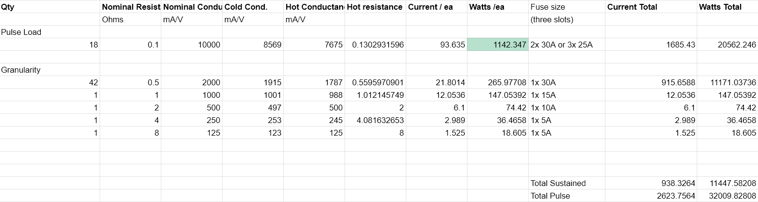
I'd initially planned on using mostly 1000W 0.25R resistors to make the bulk of the continuous load, however they doubled in price during design and so they are no longer cost effective.
Wanting a certain number of resistors switched in and out is a far cry from an actual implementation. How do you mount them? Wire them? Cool them? Control them? Prevent the switching FETs from getting damaged by the inductive spike on each turn-off? Nothing is ever quite as simple as it appears.
System Overview
The system consists of four primary parts:
- Load Stages - A single load resistor and it's associated switching and monitoring circuitry bundled in to one unit
- Connector PCB - Any power supply being tested (which I'll call the DUT - Device Under Test) connects to the Connector PCB. From here cables are run to each load stage to distribute power.
- Control PCB - The brains of the operation. Takes input from the user, and enables the correct combination of load stages to produce the desired load. Monitors temperatures and current of each load stage, produces an analog output current signal for an oscilloscope, and much more.
- Mechanical chassis - Holds all of the load stages and other boards, provides fan mounts for airflow, and is designed to be backed up to a window so all the heat can be dumped outside.
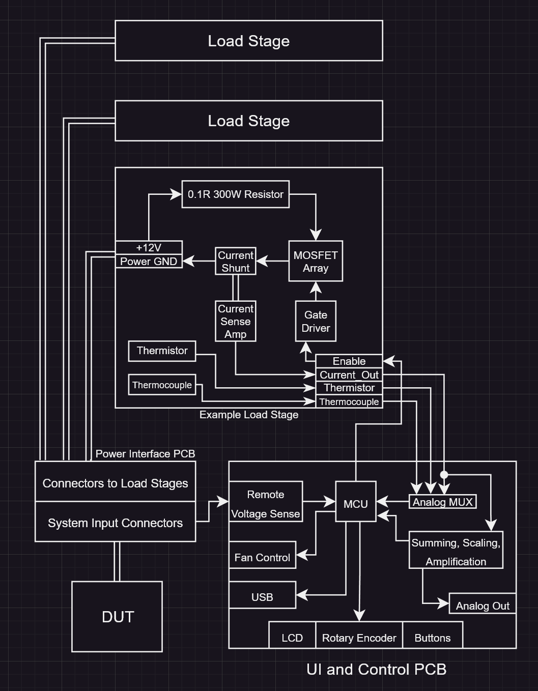
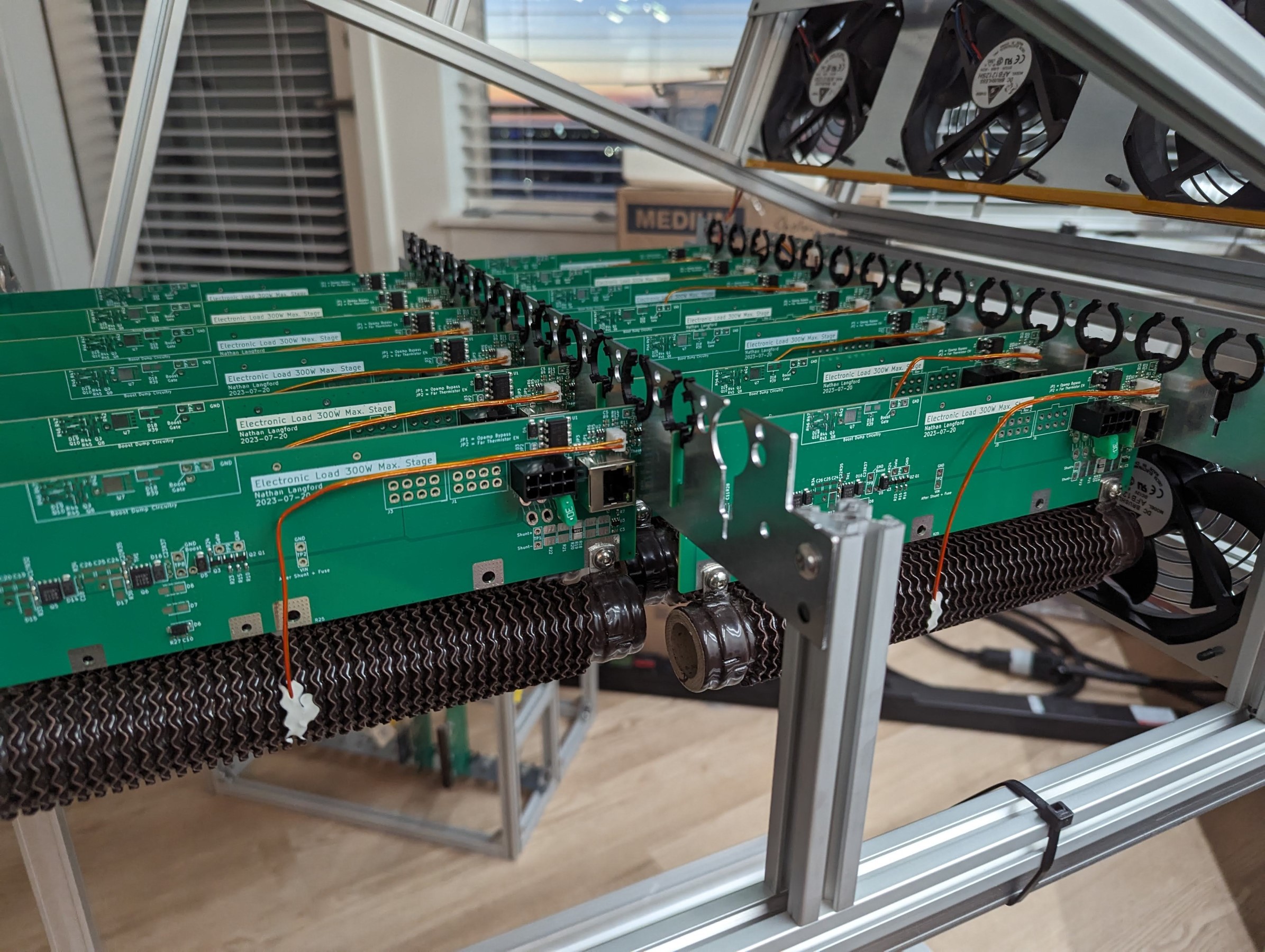
Load Stages
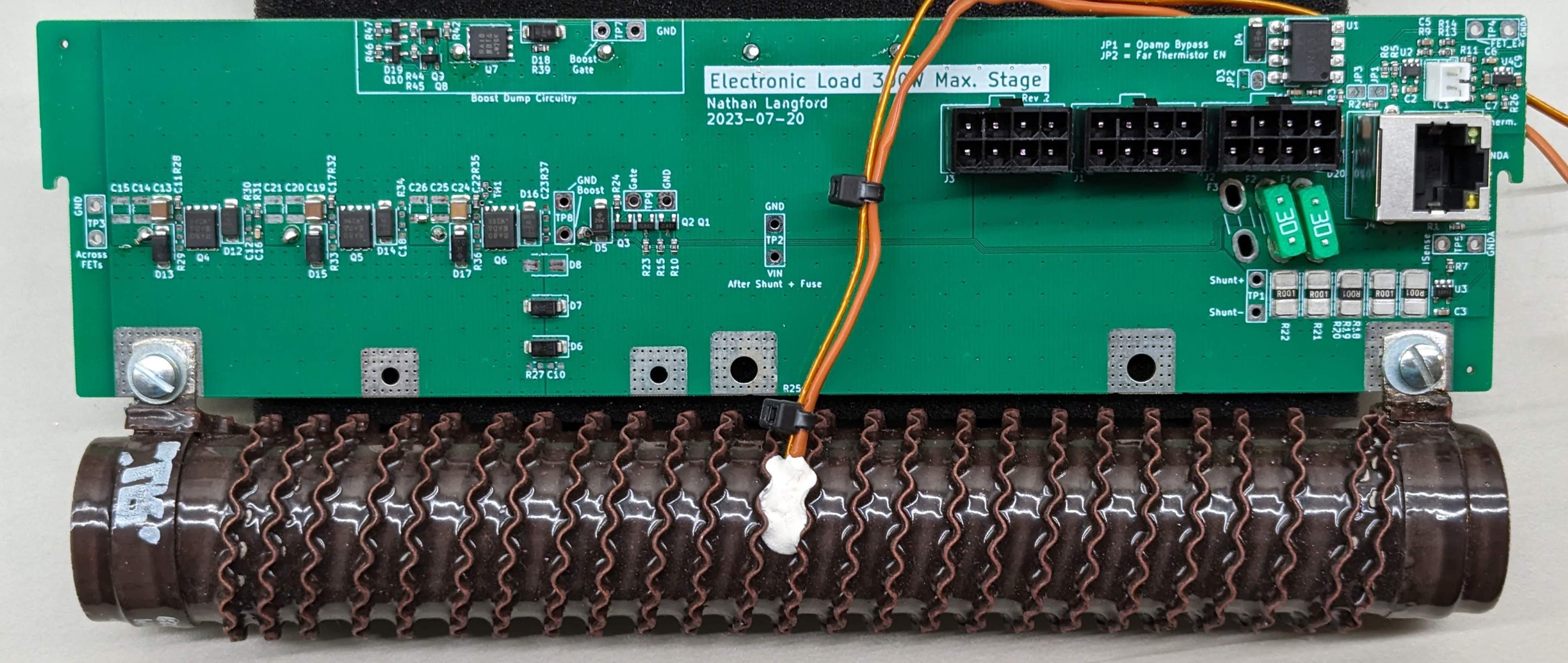
Each resistor will be attached to its own PCB to create what I'm calling a load stage. The load stages will all be connected in parallel to the system inputs. The load stages are self-contained and provide the following functions:
- MOSFETs to enable the load stage to consume power.
- Logic level input gate driver
- Isolated to prevent ground loops
- Using discrete components for lower cost
- "Boost dump" circuitry to capture the energy from the inductive spike on turn-off, and dissipate it slowly.
- When switching 122A repeatedly, the amount of energy stored in the inductance of the cables inside the system is large. Estimating 300nH total from the DUT in to the system, and then in to the load stage, that is 2.23mJ on each turn-off, or 7.37W at 3.3kHz. It gets even worse when you consider the inductance of the load resistor could be around 5uH. In simulation, this boost dump circuitry has to dissipate up to 30W when switching under a worst case scenario.
- Current measurement
- Thermocouple input and amplifier
- For measuring temperature of the load resistor to prevent overheating, and potentially compensate for their temperature coefficient of resistance.
- I'm actually using a INA180 current sense amplifier as the thermocouple amplifier. What cheaper way to get a 200x gain difference amplifier with very low input offset voltage?
- I'm also making the thermocouples myself by spot welding thermocouple wire with a cheap Li-Ion battery-based spot welder intended for battery pack nickel strip welding.
- Thermistor for software cold junction compensation of thermocouple
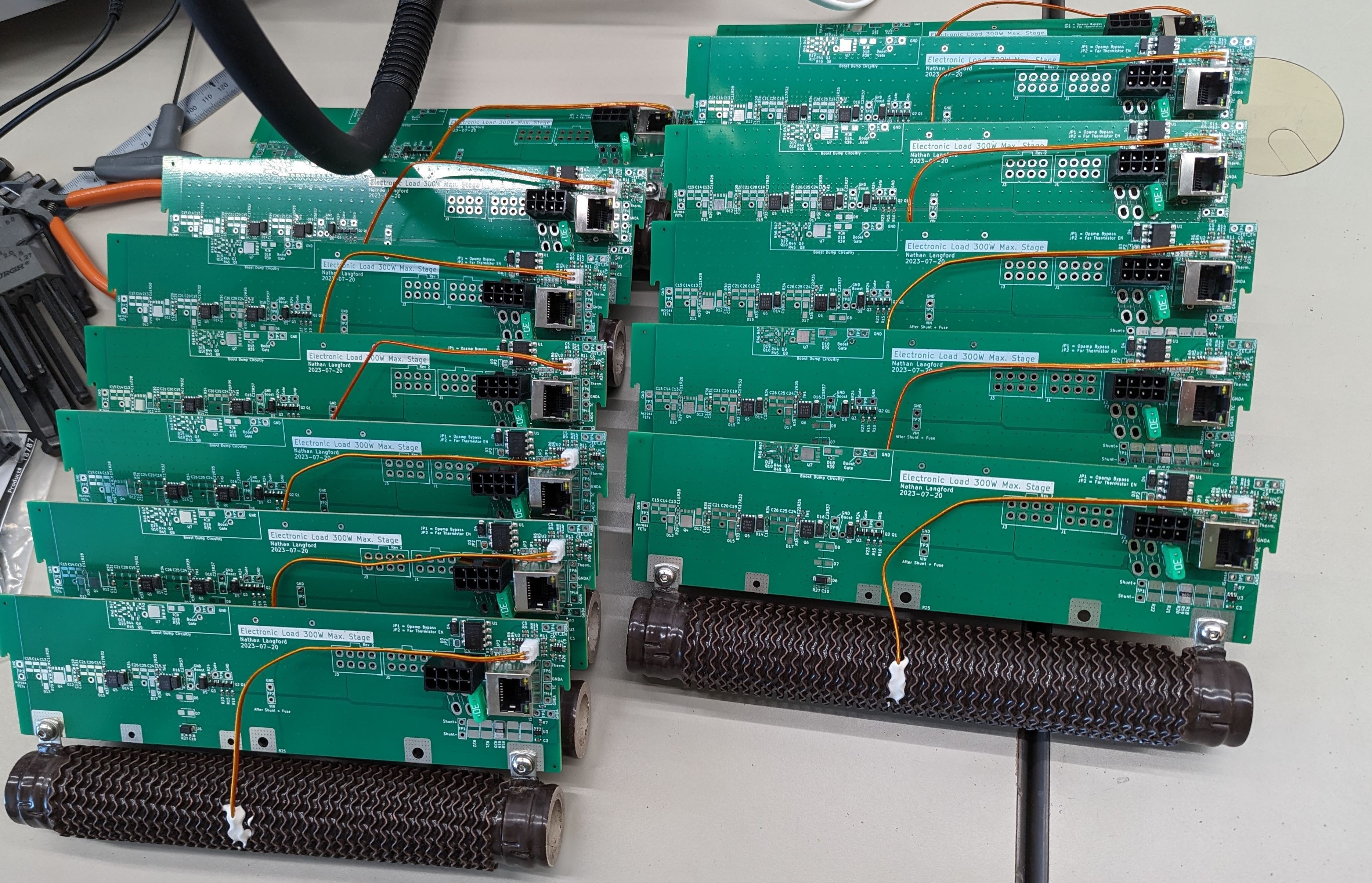
Since each load stage is completely independent, the system can be easily scaled down to 1 load stage (although you only get one bit of resolution of load this way: off and on), all the way up to the 64 load stages needed to hit the headline specs of 10kW continuous / 30kW pulsed. The first prototype was designed for 8 load stages. Then, after verifying the design was sound, I scaled it up to 64 stages. Need more continuous load? Just add 0.5R stages! Need more pulsed load? Just add 0.1R stages!
Connector PCB
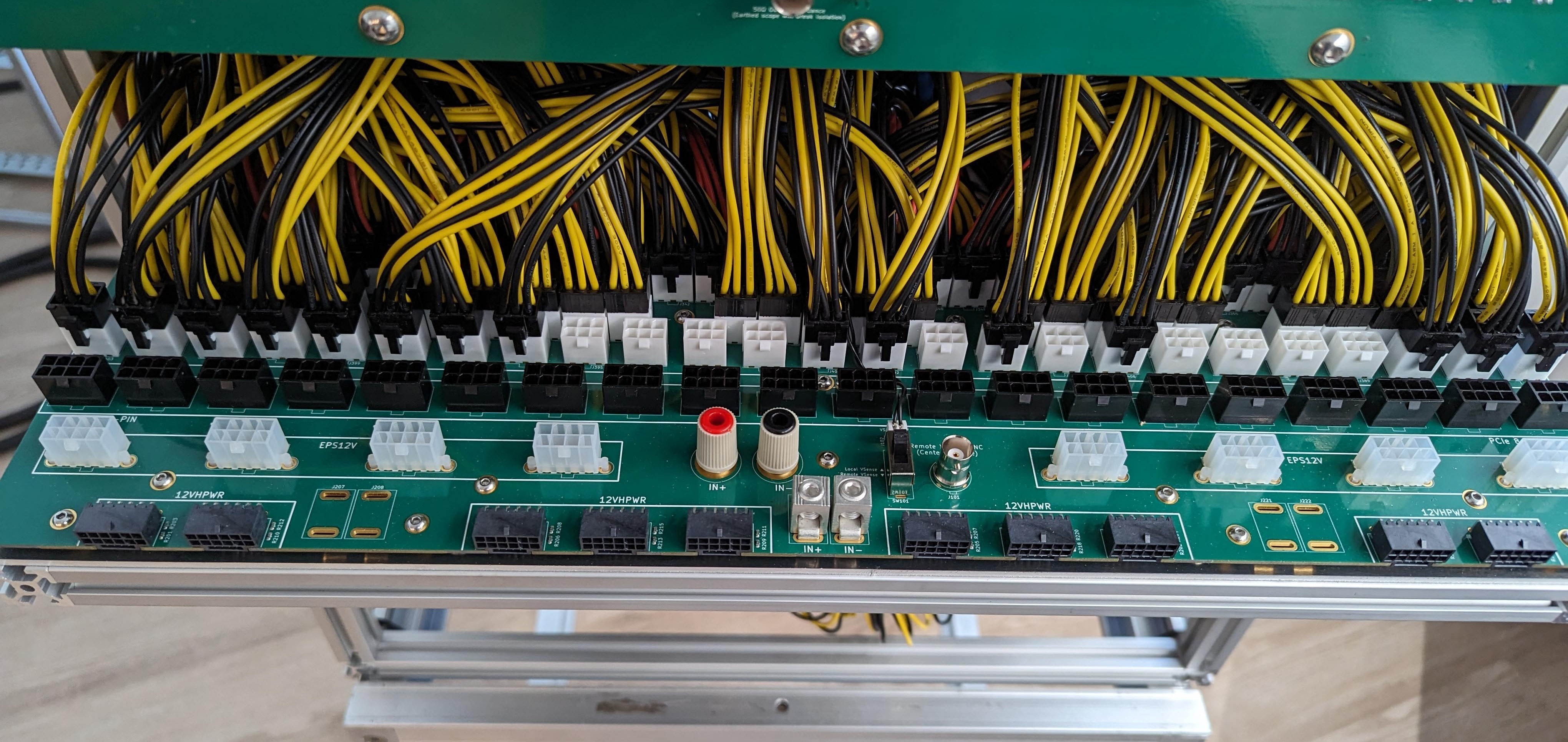
The connector PCB is probably the simplest board in the system, with no active components: just many connectors and wide copper planes to connect them. The DUT is connected to any of the front connectors, and then the rear connectors are used to distribute power to all of the load stages. Each load stage connects directly to this.
This board does highlight an important principle of the entire system though: keeping everything electrically short and wide. With the amount of current everything has to support, all of the PCBs need to be mostly copper planes that are as wide and as short as possible. Even the cables run to the load stages do this. They are many wires in parallel, which is actually better than fewer thicker wires when it comes to the cable inductance that threatens to destroy the load stage FETs if not managed during high frequency switching. This board also provides a voltage sense signal to the control PCB, with the option of having four wire sensing.
Control PCB
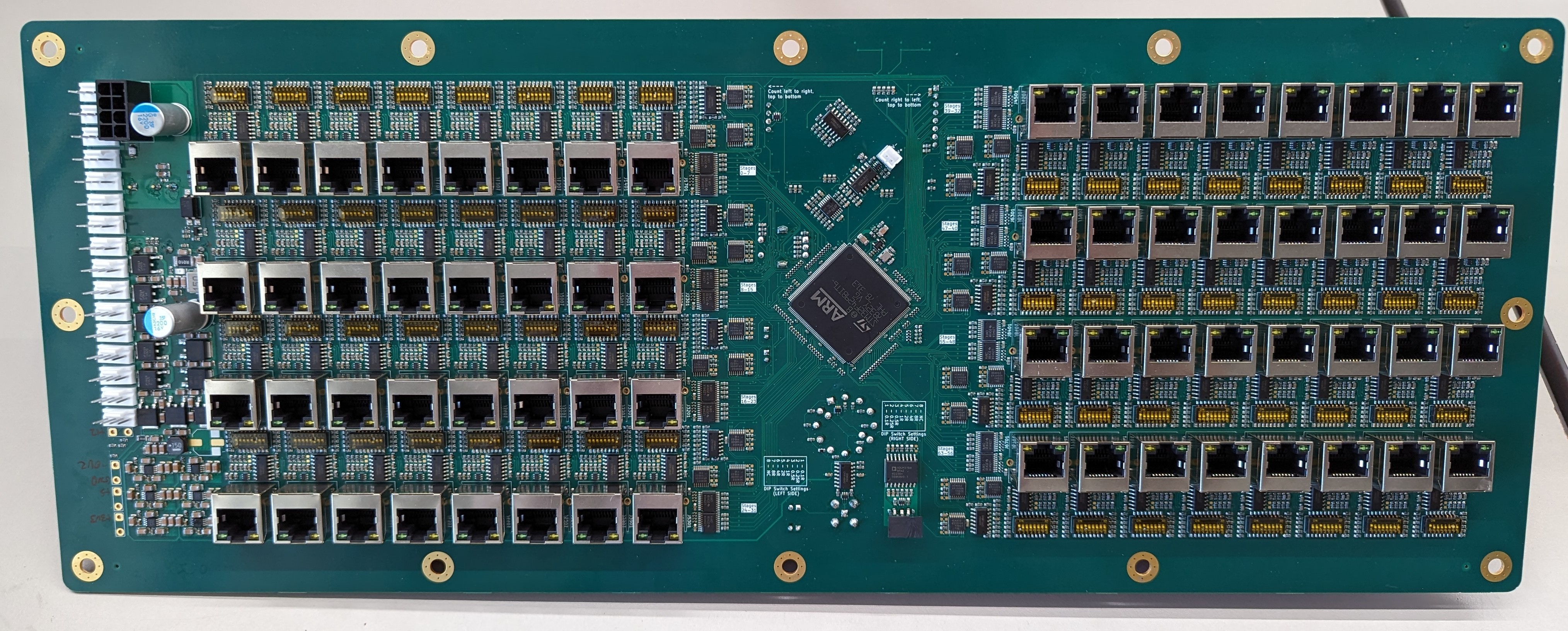
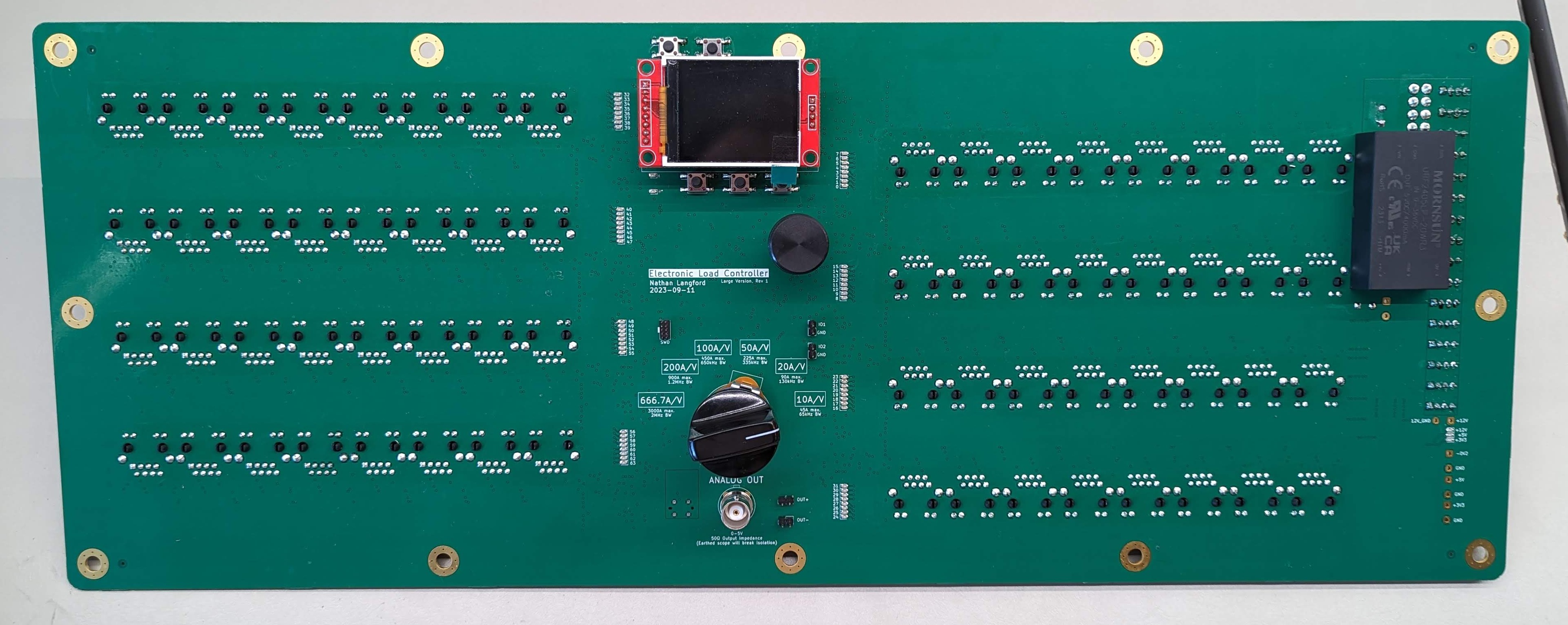
The control PCB has been probably the most complex part of the design. It has to interface with the user, control all of the load stages, and monitor the system's operation, among other things.
Features:
- STM32 microcontroller
- Precision voltage reference
- Ultra low offset voltage op amps
- Analog summing of the current sense signal from each load stage, after scaling for it's absolute current value. All designed to keep error under 1%.
- Analog current waveform output for an oscilloscope with variable output gain.
- PWM fan control
- Completely isolated to prevent ground loops
- 12V, 5V, 3.3V power rails with additional filtering, including -0.2V power rail to allow op amps to swing to 0V.
- Isolated USB for PC data transfer
- Input reverse voltage detection and alerting
- TFT LCD, rotary encoder and buttons for user interface
- Multiplexing and filtering of thermocouple, thermistor, and current sense signals from each load stage (Over 192 analog signals!)
- Differential amplifier for four wire remote voltage sense
- DIP switches to configure load stage current sense gain setting before analog summing
- RJ45 connectors and cables for control and sense connections to each load stage
- Buffers to drive enable signals to load stages and associated LEDs
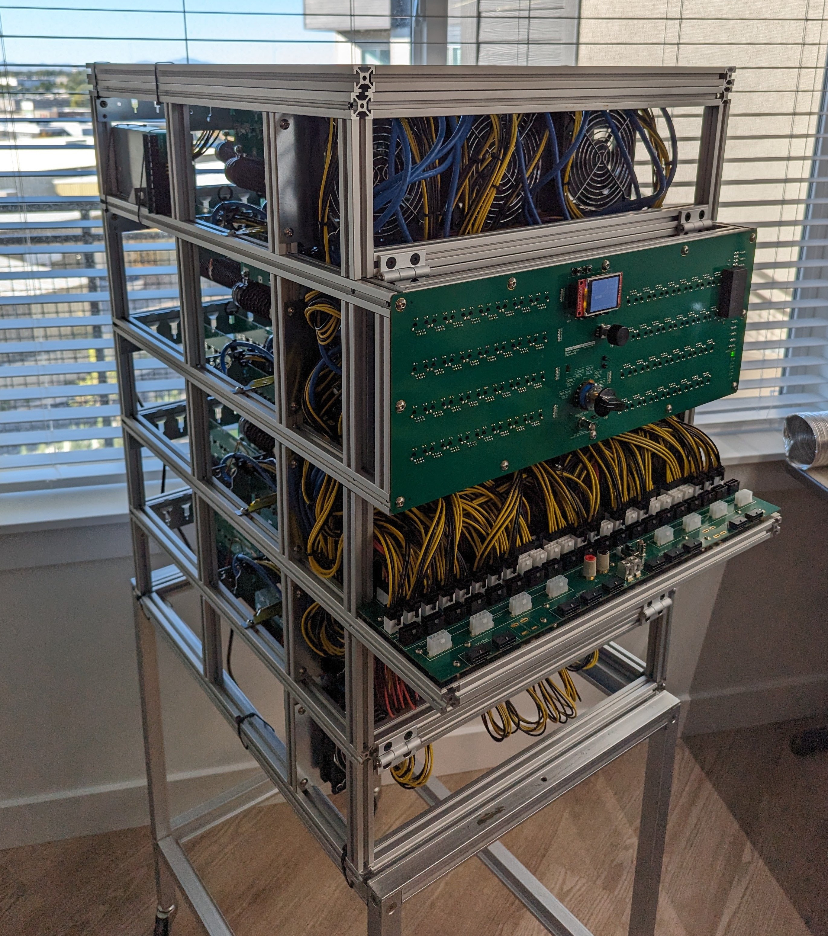
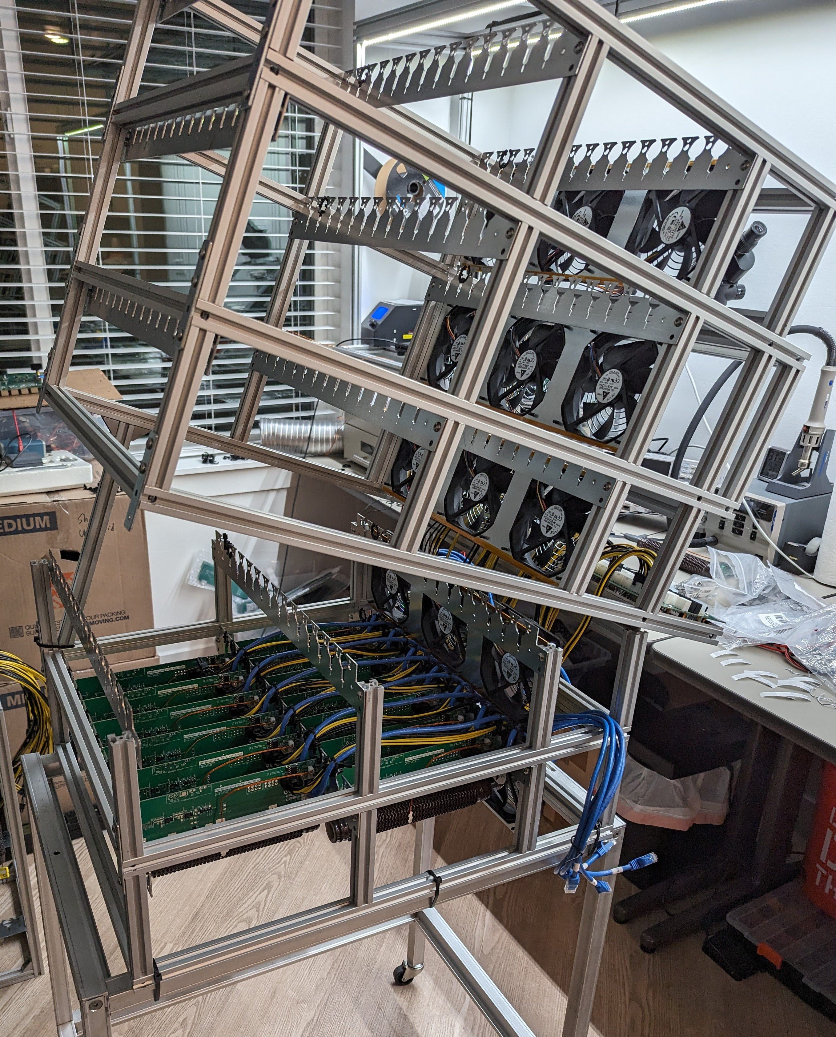
Mechanical Chassis
Designed to scale like everything else, the chassis consists of multiple levels that are bolted together. Each level supports 13 load stages and three 120mm fans.
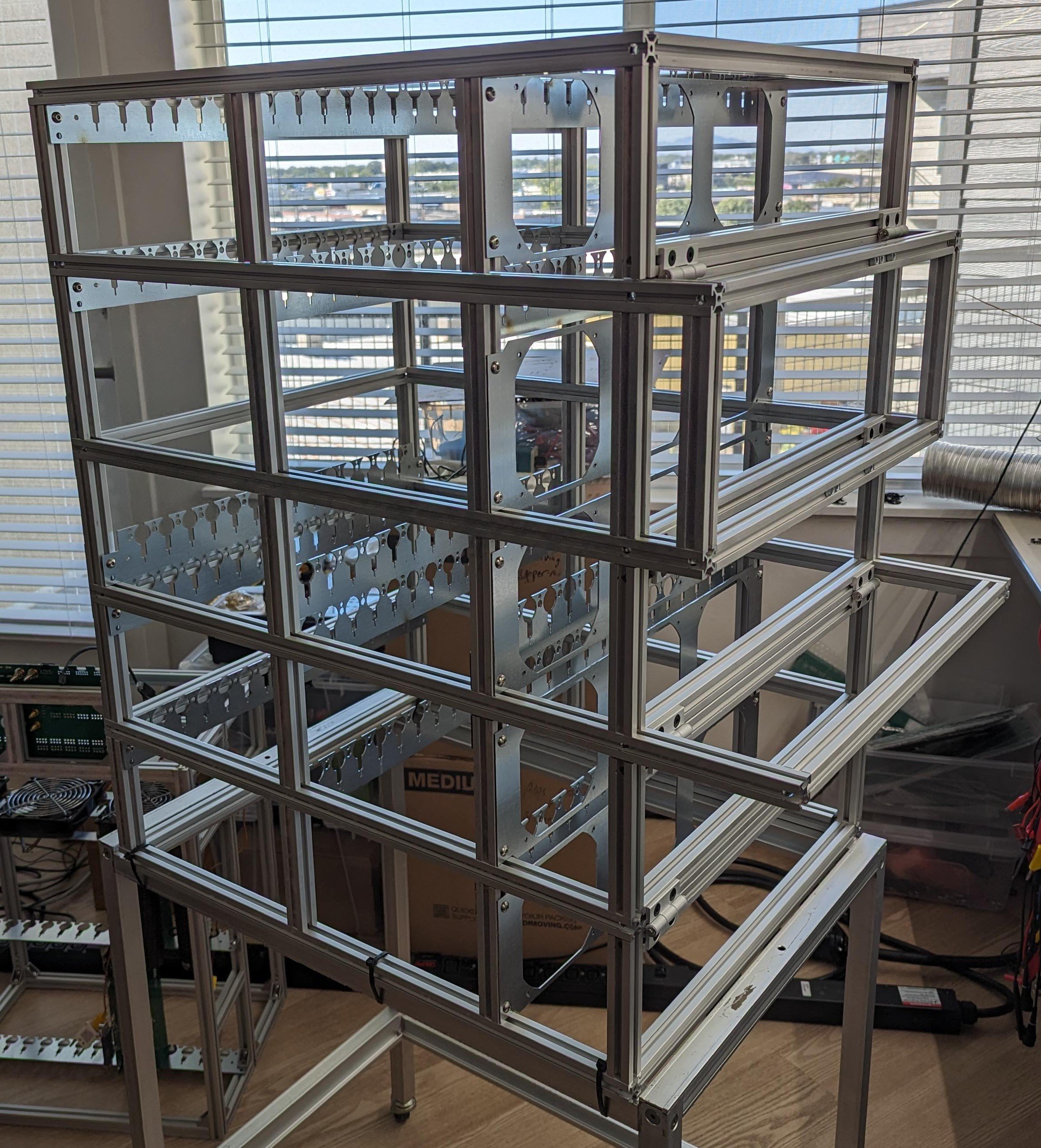
Load stages are mounted by using hooks in the PCBs that slot in to sheet metal cross pieces. The cross pieces also act as cable guides and include 3D-printed retention clips to protect the cables and retain the load stages in their slots.
During work on the first prototype, it became clear maintenance was going to be an issue in accessing any of the lower levels. To solve this, the chassis is design so that the system can hinge forward at each level to provide internal access.
Why resistors?
Given the chassis-mount resistors are the heart of the system. One might ask: why on earth would you choose that? Here are some of the design considerations:
- Low cost per watt of heat dissipation
- The cost of a 300W wirewound resistor in the values I'd need is about $23. I don't think there is a cheaper, realistic way to burn and dissipate power.
- Essentially replaced the need for both MOSFETs as the load and heatsinks to keep them cool.
- If I need 34 of them to hit 10kW, that's $782, which is cheap compared to any other option. Using the traditional MOSFETs and heatsinks would cost over double that.
- Can be operated at higher temperatures for more efficient heat transfer to forced airflow
- By running them at higher temperatures (rated up to 250C), more heat can be transferred with the same volume of airflow. Meaning fewer or slower fans can be used.
- Rated to withstand overloads of 5x their rated power for 10 seconds
- 300W 0.1R resistors can be used to generate 1500W load pulses, and they can handle it as long as the long term average power stays at or below their nominal 300W.
Napkin Math on the cost of MOSFETs and heatsinks
Most electronic loads these days use a MOSFET in linear operation driven by an opamp to sink a set amount of current. The MOSFETs are the load and all of the energy must then be dissipated in to a heatsink. Given the scale I'm working at, two problems come to mind: MOSFET quantity and heatsink capacity. Starting with just the 10kW continuous load spec, how many MOSFETs would we need?
Looking at some commercial units, here's what we see:
Rigol DL3021 - 10x IRFP250N @ 200W/40A
Siglent SDL1020X-E - 12x IRFP250N @ 200W/30A
Kunkin KP184 - 6x IRFP250M @ 400W
BK Precision 8601 - 10x IRFP250N @ 250W
East Tester ET5410 - 6x IRFP250N @ 400W
Interestingly, nearly everyone is using the same MOSFET type. They are loading them at a range of 17W-67W each. 67W each makes sense since the IRFP250N datasheet indicates 0.7 C/W junction-to-case + 0.24 C/W case-to-heatsink thermal resistance = 0.94C/W * 67W = 63C temp rise. Assuming at 50C heatsink, the MOSFETs would be at 113C which is pretty toasty although the datasheet max temp is 175C. At 67W each, we'd need 150 of them to do 10kW. On LCSC, these MOSFETs would be $0.48 each at this quantity, so it's not completely insane at $72 total for the FETs.
There is a lot of information online about how not all MOSFETs operate in the linear range reliably, and almost no MOSFETs are actually rated by the manufacturer for continuous operation there. IXYS makes some and they have a lower junction-to-heatsink thermal resistance of 0.56 C/W so we might be able to push 113W through each with the same temps, but they are much more expensive. We'd need 89 of them and they are $8.17 each in that quantity, so we're looking at $727.13 in MOSFETs. Ouch.
However, there is a larger problem that the cost of the FETs: the heatsinks. How exactly does one sink 10kW of heat? Lots of large aluminum heatsinks in rows? Water cooling with radiators? How much would that even cost? It all comes down to dollars/watt of heatsinking.
Given the whole point of this project is to keep the costs low, I think we'd have two options:
- Extruded aluminum heat sinks, like are common in commercial electronic loads
- Looking at this heatsink from Digikey so we can get some actual specs to work with, it is 40x93x300mm in size with 28 fins, and rated for as low as 0.4C/W at 400 LFPM of airflow, per inch of extrusion. In theory the whole 300mm heat sink might hit 0.034 C/W. If we want to limit the heatsink to 50C in a 25C environment, so the MOSFETs stick to the 113C junction we calculated before, we could dissipate 735W per heatsink. That seems...high?
- (It was at this point of the write-up, I realized that perhaps I shouldn't have dismissed the idea of using FETs and heatsinks.)
- Running the dimensions of the same heatsink through this calculator, we get 0.13C/W or 192W. That seems more sane.
- If we run with this 39x69x300mm heatsink from AliExpress at $24.30 each, and the aforementioned calculator, we could dissipate 147W. This gives us a cost of $0.165/Watt. For 10kW, we'd need 68 of these heatsinks for a total cost of $1652.
- I'm going to rule this out due to cost.
- CPU heatsink + fan coolers, which are cheap, readily available, and designed for sinking high thermal density sources
- Let's be optimistic and say we can get a CPU cooler capable of cooling 150W for $10. That's $0.067/Watt or $670 for 67 heatsinks. That's actually quite cheap, possibly unrealistically cheap?
- How would we mount 67 CPU coolers in a way that makes any sense? Where would the PCBs with the MOSFETs be?
- I don't think there is any way to do it without it being enormous and unpractical.
More design info
Even with all of the above I've written, I feel like I've only scratched the surface in explaining how and why everything was designed like it was (for good or bad). It feels like I could write a book with as long as I've been working on this). For more information on the design process, I'd encourage you to look at the project logs I've posted. I go further in to the gory technical detail in some of those.
Future Work
As far as this project has come, there is inevitably a lot of room for future improvements.
While the custom cable management clips have worked well for the cables around the load stages, the space in front of the fans but still within the chassis is, not ideal, to put it lightly. It would be a lot of work if a cable needed to be replaced. The issue is that there are just so many cables (over 160 at least) and the cables have to be as short as possible to minimize the inductance going to the load stages. It might be interesting to consider if a backplane system could be implemented somehow to eliminate most of the cables altogether.
The cables may also create an issue with airflow through the system. In theory the system was designed to support stronger 38mm thick fans but I'm not sure there is actually room for that, and the cables would be a significant impediment to actually trying to swap fans. I believe it would be relatively easy to add some sheet metal brackets to the rear of the system, on each level, and then install an array of 120mm x 38mm fans on the back to pull air through the system. This would resolve any issue with the cables causing airflow restriction through brute force. It would also necessitate the next upgrade though: sheet metal side panels.
Currently, there is nothing stopping the air from the fans from escaping out the side of the system, depriving the rear stages of airflow, and dumping the system heat indoors instead of outdoors (assuming the load is backed up to a window). It would be relatively straightforward to add sheet metal to the sides, top, and bottom to guide the air straight through.
Firmware
Available on Github: https://github.com/tinfever/10kW-30kW-pulse-Electronic-Load-Controller
Open Source Licensing
All hardware designs, schematics, software, documentation, and any other published material is licensed under the CERN Open Hardware Licence Version 2 – Strongly Reciprocal.