This is just going to be a quick update post showing off everything that's happened since the last post. Cue the pictures!
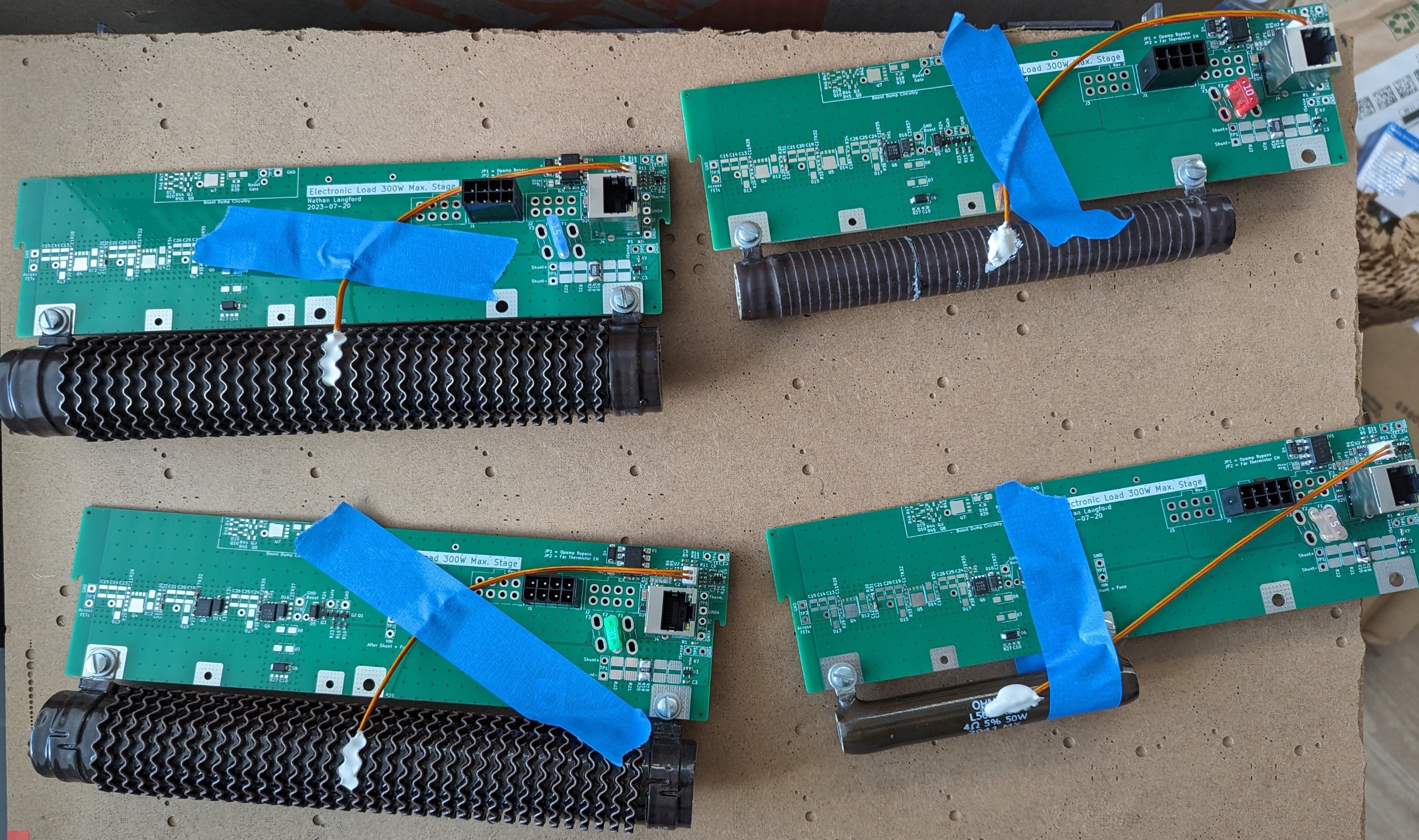
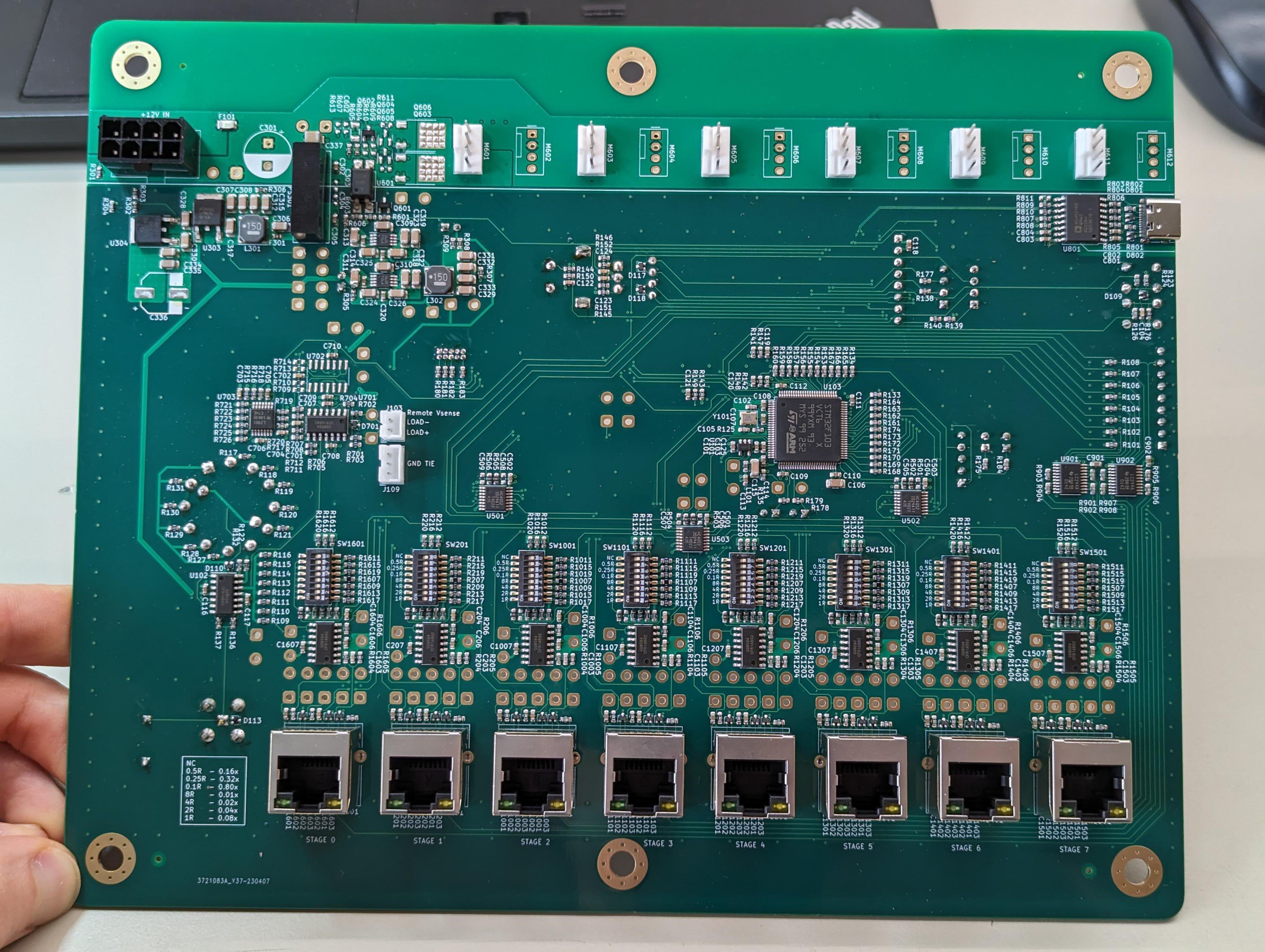
The new load stages PCBs arrived. These feature:
- Updated optocoupler circuitry to greatly reduce turn-off delay.
- Switched to using MINI blade fuses, sometimes in parallel, to reduce cost dramatically. Those previous MAXI fuses could be nearly $3 each, and the MINI fuses are around 0.08$ each!
- Relocated the capacitor Cgd on the FET to be as close possible. Also, added series resistor with it to dampen the oscillation it caused. (Kind of feels like a dirty hack but it works...or at least now I can't see it)
- Added thermal reliefs to all the through-hole parts. Last time I discovered they are definitely not optional. I might need to make them even thinner next time since those PCIe connectors are still hard to solder and need a pass from each side of the pin. They are going directly in to solid planes though.
- Moved the gate driver transistors much closer to the FETs.
- Switched to a different TVS diode type to align with the PCB assemblers preferred parts (and they are just cheaper and just as good otherwise)
- Added a series resistor to the NPN push transistor in the gate drive. This allows input voltages to go higher than 14V without quickly being at risk of burning up the FET gate protection TVS.
- More optimized gate driver pull-up transistors to reduce quiescent current consumption

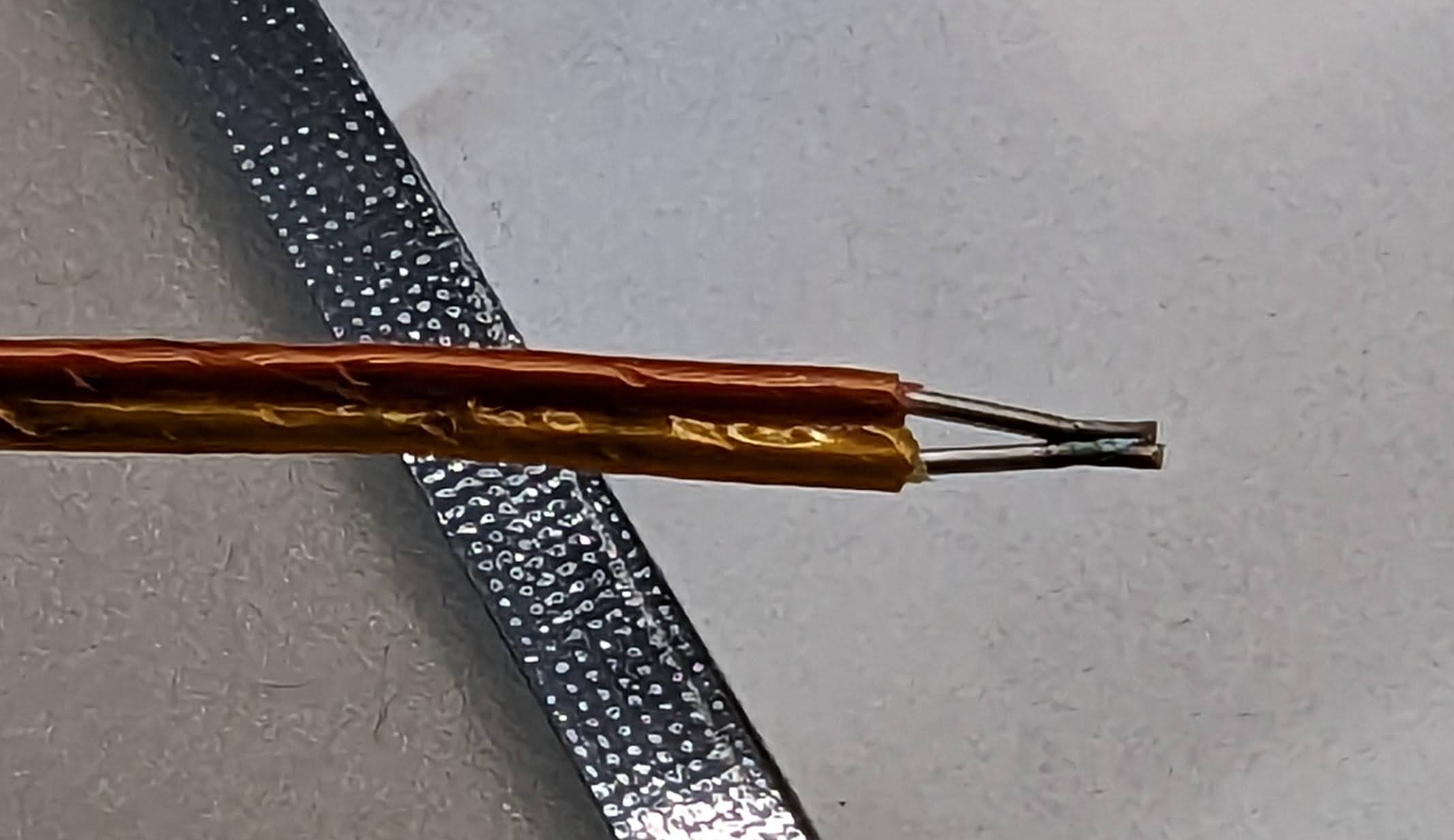
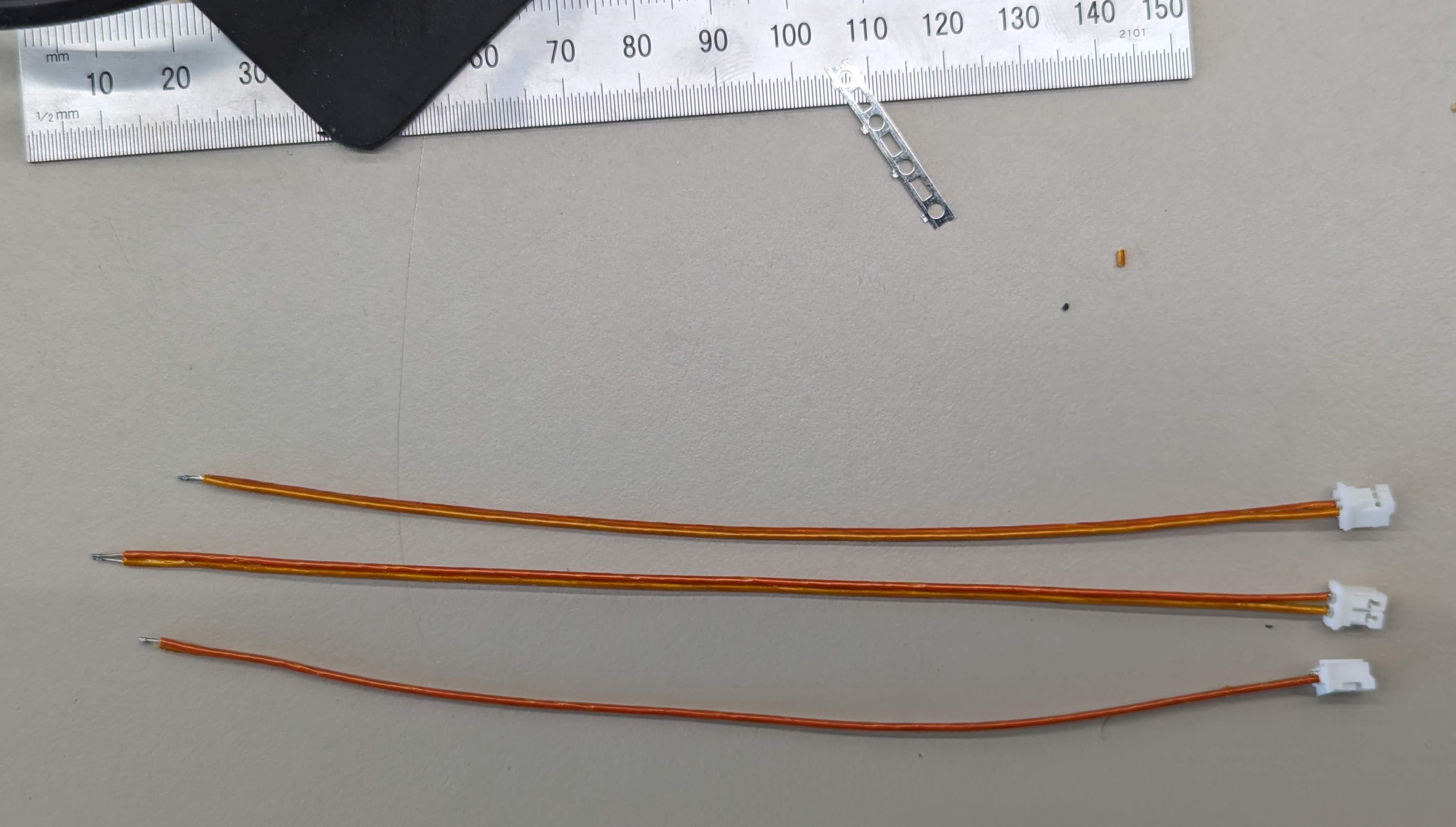
Thermocouples have been DIY spot welded, crimped, and epoxied to the load resistors. The thermocouples will someday get their own post but I'm using a cheap Li-Ion battery based spot welder intended for welding nickel strips when making battery packs. It works pretty well for this. The epoxy has to be a special high-temp cement (CC HIGH TEMP from Omega) to survive the 250C+ of the load resistors. I tried JB-Weld first a while ago but that just becomes soft and falls apart at those temperatures.
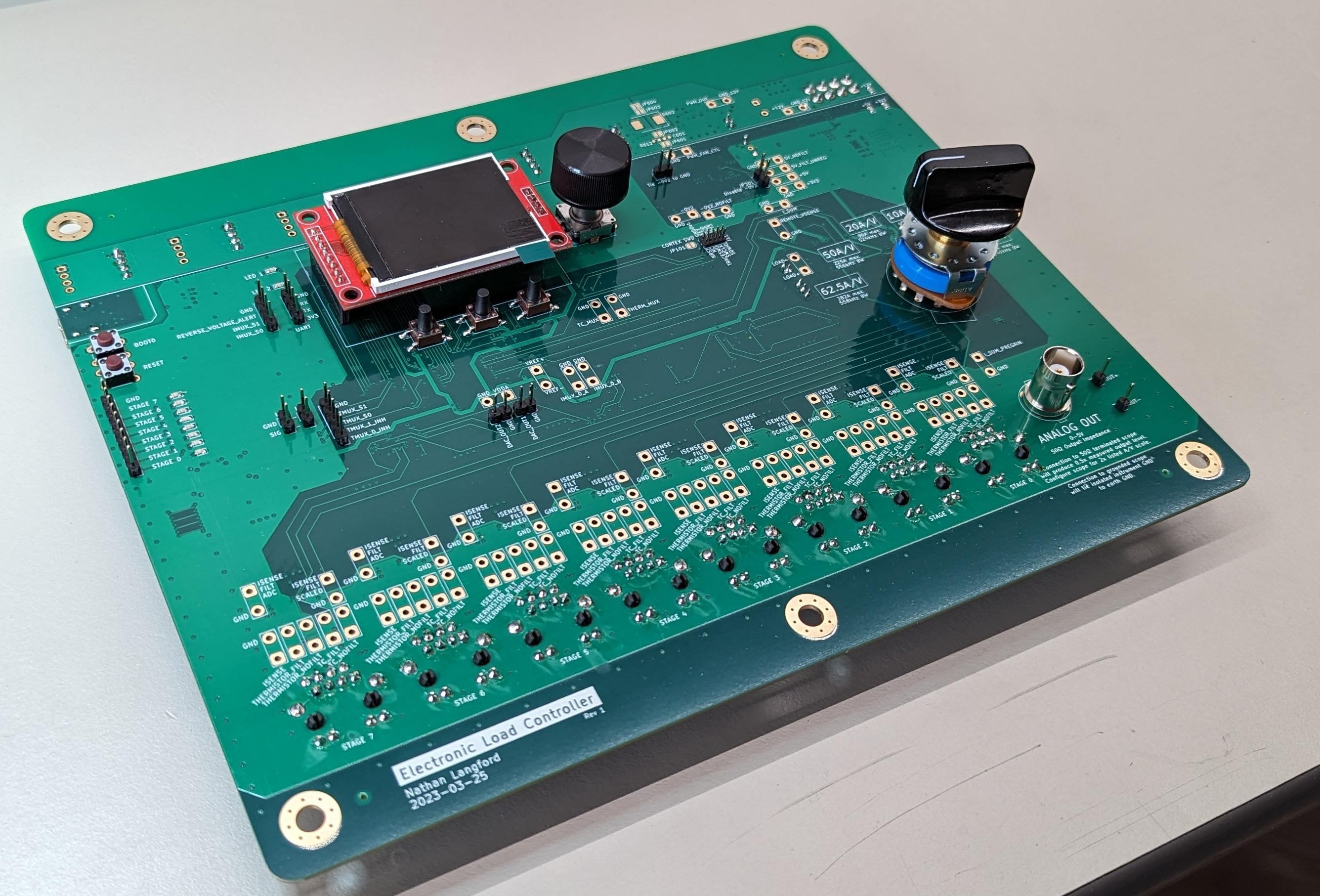
Main Control PCB Assembly
The control PCB has over 570 components on it, which was rather painful to pick and place by hand. I timed myself and it took me almost exactly 5.1 hours to place the 511 SMD parts on the back. So I can do about 100 parts per hour. Not great, but there is a high component mix with 65 unique parts on the back. This whole system I'm working on right now is the prototype so the control PCB only supports 8 load stages. If all goes well, a future version will support the 50+ needed.
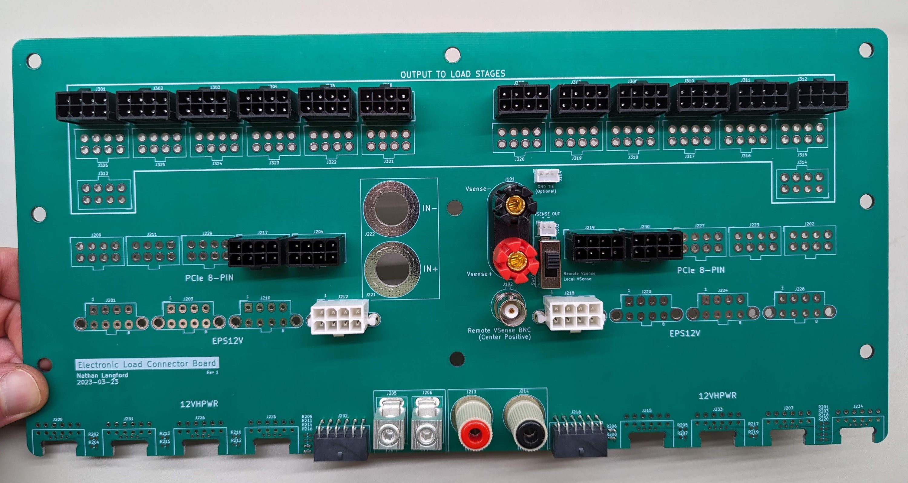
Connector PCB Assembly
This board has the job of taking in power from the DUT and distributing it to all of the load stages which operate in parallel. It also provides a remote voltage sense signal for the control PCB. It's only partially loaded here to support the max current levels I'm expect to hit on this prototype. The binding post solution on this is pretty weak since it's clear to me these were designed for panel mounting and not an electrical connection to a PCB.
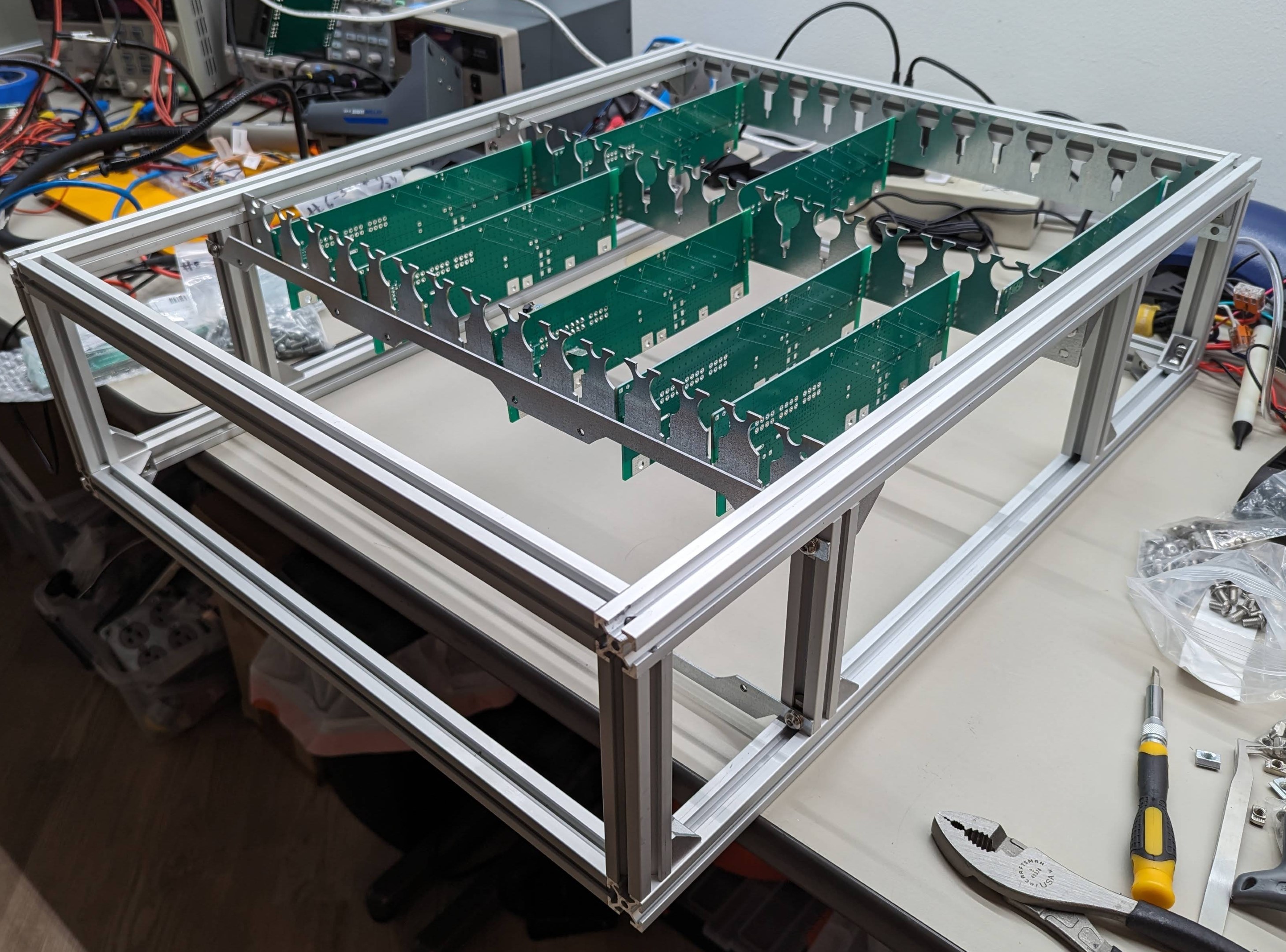
Putting together the mechanical chassis
Here is the first level of the chassis. Like everything else in the project, it's designed to scale to multiple levels. Each level can hold 13 load stages and three 120mm fans. I'm not sure what possessed me to use PCB hooks as a mounting mechanism for the load stages. It'll work because the whole thing is stationary but otherwise not a great solution. I suppose it is cheap though!
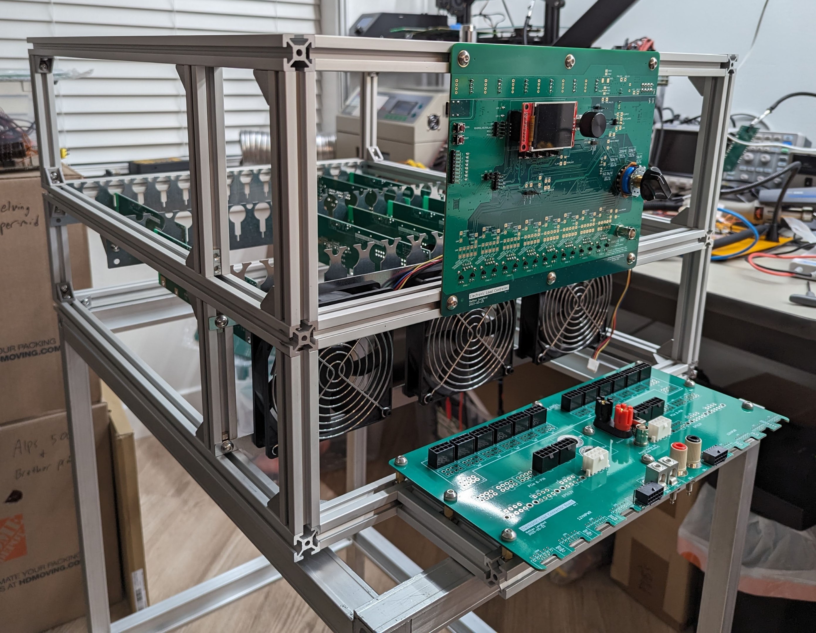
Putting it all together
This has the second load-stage chassis level installed which also provides the mount for the control PCB. There is an extension of the chassis the sticks out the front for the connector PCB to mount to. The connector PCB has to overhang that a bit to support the right angle connectors on the front edge as well as the binding posts. I suppose since I used standoffs anyways, if I moved the binding posts around that could probably be eliminated. It's now sitting on an unrelated aluminum frame cart so I can still use my workbench, and also so I can back it up to a window to exhaust the heat directly outside.
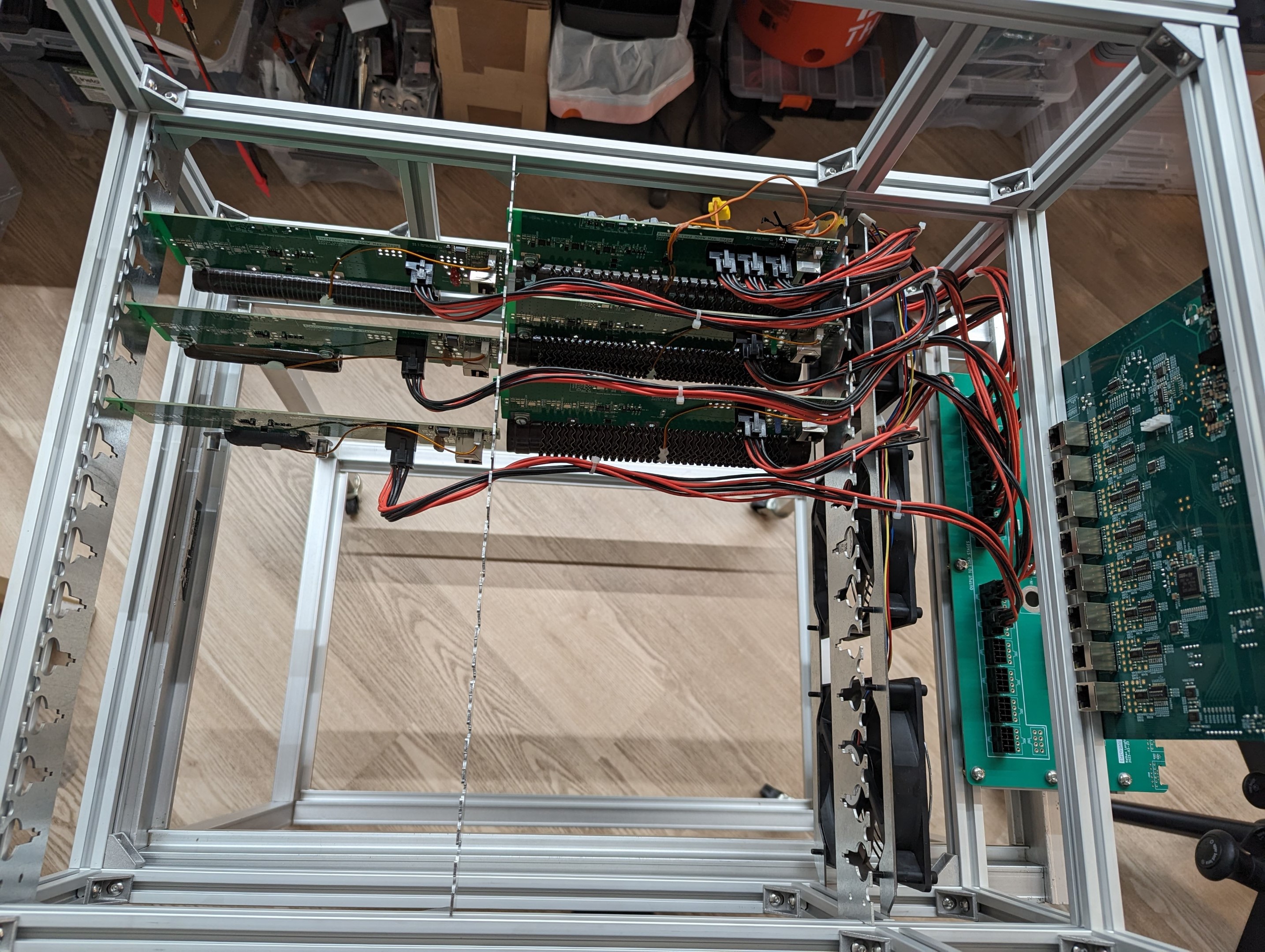
Adding in some preliminary wiring
You can see here how each load stage connects to the connector PCB. Cable management is going to be a big challenge. This small version only has 7 cables now but the full-size version with all load stages populated will have over 70 power cables I believe. I think it will work but maintenance is going to be a nightmare. I'll probably need to redo the load stage mounting pieces / cable guides. I'm going to try to 3D print plastic inserts to go in the cable guide sections to protect the cables from the sheet metal edges and to act as retaining clips for the load stage PCBs. I'll probably build in zip tie points as well. If I also shorten the front load stage power cables to reduce the excess, I might stand a fighting chance. However, if I have five levels of these with 13 load stages per level, I'm going to need some way to de-stack the various levels for maintenance access. I've learned before that planning on not needed much maintenance is a bad idea.
Software
With the electrical and mechanical hardware done, the only thing left is the software. I use the term "only" very loosely here because the software is going to be a major undertaking.
Software goals/wishes:
- Input voltage and total system current measurement and display
- Individual load stage current draw measurement
- Precise load stage sequencing and correct combination enablement
- Constant and pulsed current mode, with configurated high/low levels and timing
- Closed loop load stage sequencing to handle any input voltage and minimize error as load stages vary under temperature
- Thermistor and thermocouple monitoring for each load stage
- PWM fan control based on load stage temperature
- Reverse input voltage alert
- Slew rate control (both increasing and decreasing) by either turning on faster load stages briefly at startup to allow a faster slew rate, or sequencing through the load stages slower for a lower slew rate.
- Voltage sense disconnect protection, load stage over temperature protection, current cutoff failure detection
- Individual load stage calibration?
I'm currently starting to work on the software but progress is slow. (It turns out learning as you go is very hard and time consuming.) The MCU bring up was smooth and below you can see me testing the differential remote voltage sense reading. This is literally all it does right now. So I've got my work cut out for me to get some basic functionality implemented by the deadline Tuesday.

I want to get this thing consuming current in some sort of pattern and vaguely resembling the correct value by Tuesday. I'd better get back to work! (And I realize now this post was very much not short.)
Discussions
Become a Hackaday.io Member
Create an account to leave a comment. Already have an account? Log In.