Picking up where I left off, the previous prototype with 8 stages was a success. It successfully demonstrated the principal of operation, and it also revealed areas needing attention. Building the full-size version of this project in a little over a month was really tight, but through luck, determination, and brute force, it has come through just in the nick of time (as I write this less than 8 hours from the deadline)
A ton has happened since the last update with the prototype, so this is going to be a long post. Let's go!
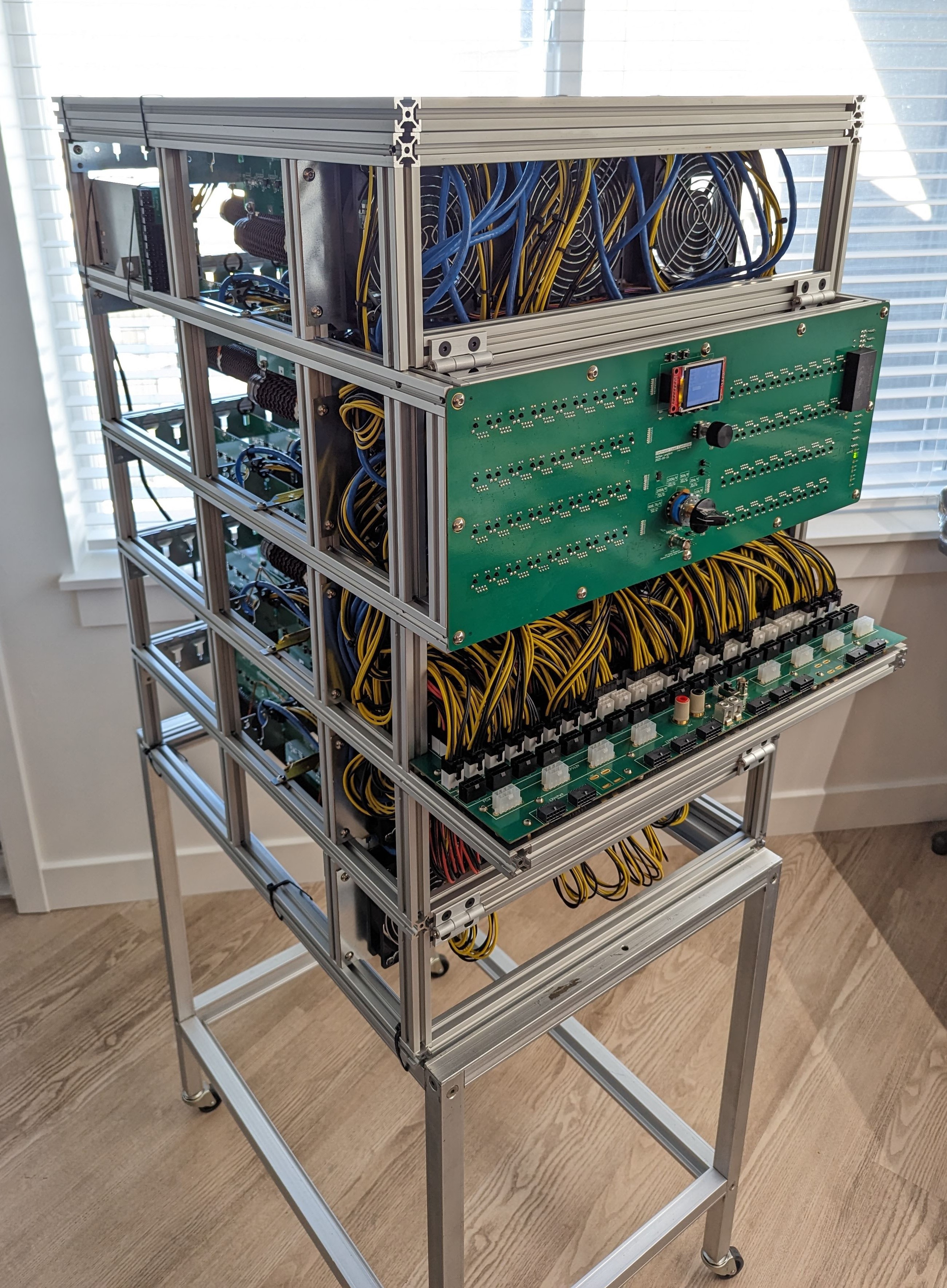
Bigger and Better Control PCB
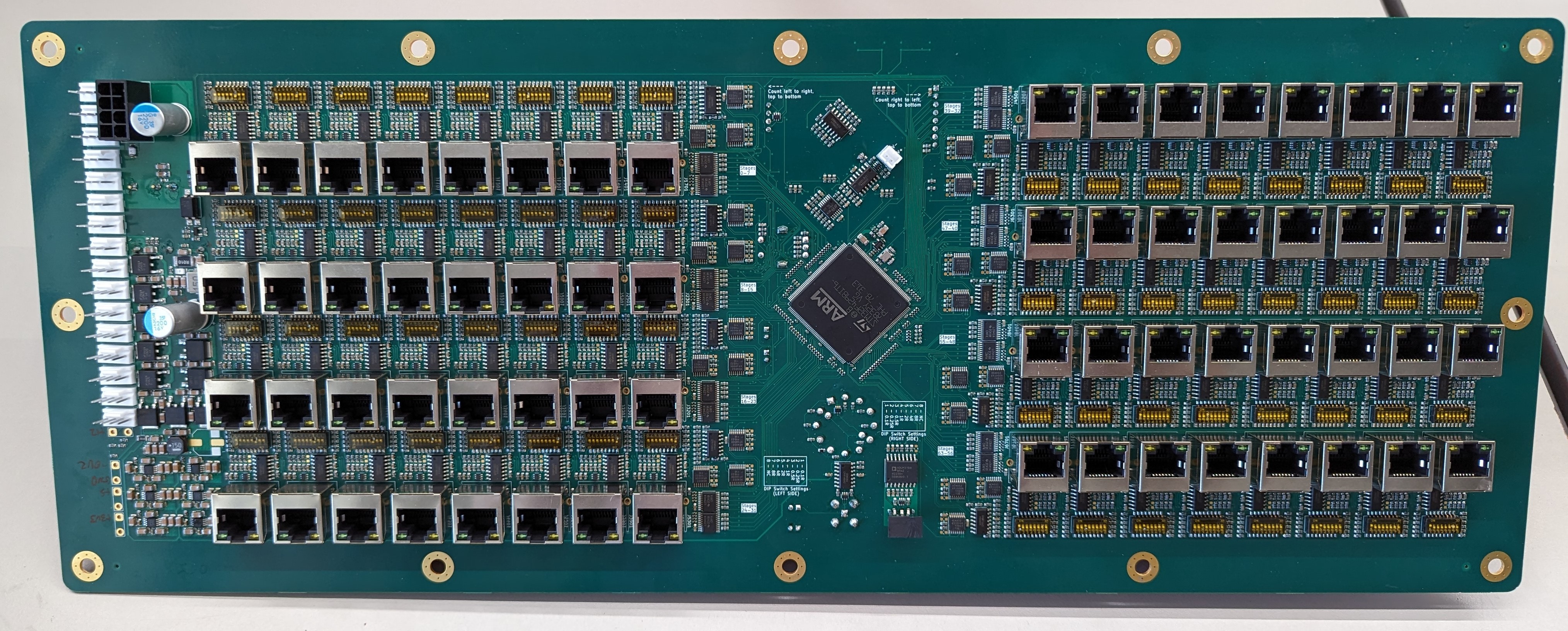
The new control PCB is kind of a monster. Here are some highlights:
- Supports 64 load stages (up from 8)
- Upgraded microcontroller from STM32F103 to STM32F429, in one of their biggest packages (LQFP-208)
- 6-layer PCB (three ground planes)
- Same analog circuitry for each load stage as the prototype, just compacted and replicated.
- Current signal analog summing now done in multiple stages for routing sanity and bandwidth improvements
- Changed buffer ICs for straight through routing
- Lower cost / more common TVS diodes
This was a tight layout but I'm really pleased with how well it came out. Still, I had to take some shortcuts. There was no room for the isolated DC-DC converter on the back side, there was barely any room for test points on the PSU section, and some of the analog trace spacing is tighter than I'd like. I'd initially wanted to support 65 stages (13 per level x 5 levels in the chassis) but it quickly became clear that wasn't going to happen.
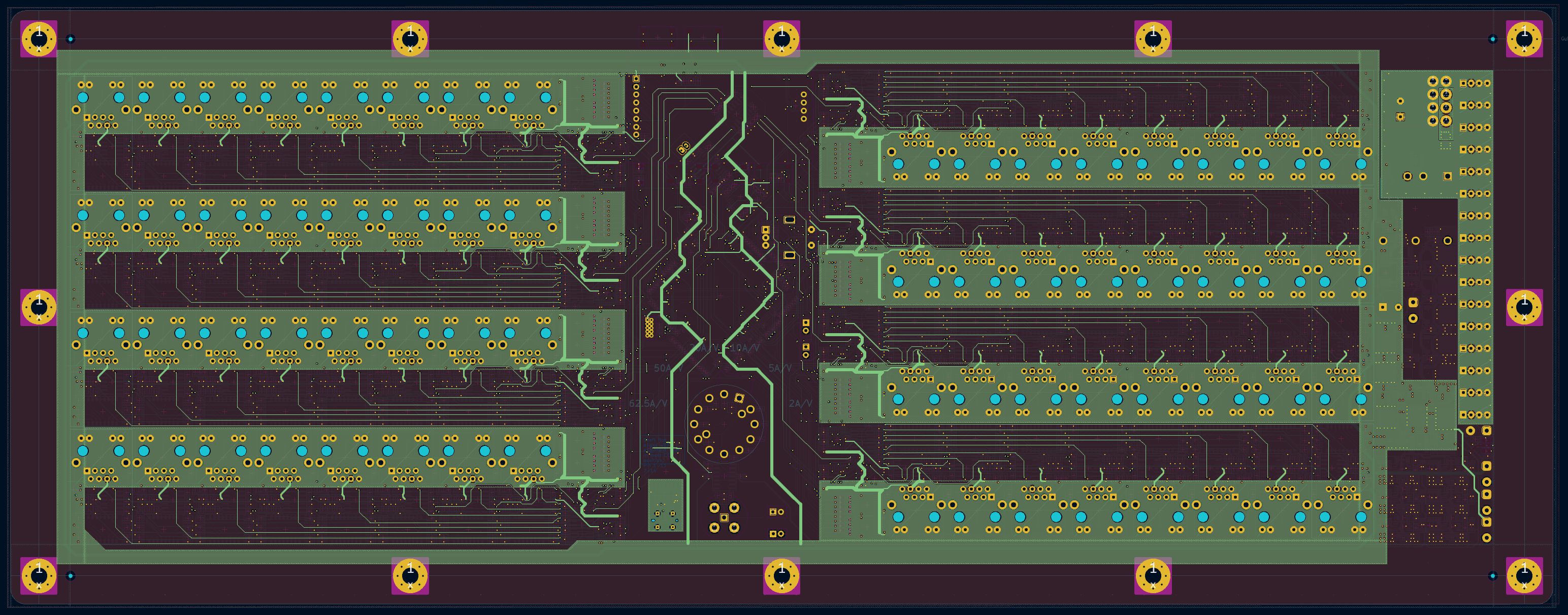
The primary reason for switching the microcontrollers was simply the need for more pins than were available in the STM32F1 family. I really wanted the enable signal for each load stage to have a dedicated GPIO pin, and for those to reside on mostly dedicated ports of the microcontroller. This is purely for speed, since switching the load stages in 100us pulses doesn't leave a lot of time to run shift registers. This way, I can directly write to the five GPIO ports where the enable signals reside and control all of the load stages in something like 10 clock cycles.
I was also hoping to upgrade to a larger screen with touch input driven by a parallel bus but I had to cut that upgrade due to time constraints. I'm still holding out hope I might be able to bodge in a 3.5" SPI touch screen though.
Why 64 stages?
One thing I found working with the prototype was that the load stages all had a higher effective resistance than their nominal rating would suggest. (I may also throw around the term "conductance" in mA / V since that is how I wrote the firmware. See the firmware post for more details.) This resistance change only worsened as they heated up.
Referring to the table below, you can see the cold (room temp.) and hot (200C) conductance values I measured in the load stages of the prototype. The 8R, 4R, and 2R stages were relatively accurate regardless of temperature. However, the 0.5R stages, and especially the 0.1R stages, were quite poor. A stage that would, in theory, be 0.1R, actually measured at 0.117R at room temp., and 0.130R when hot. I think the cold variation is from the cables and the connector contact resistance. While the hot variation is probably mostly the temperature coefficient of resistance for the load resistor.
Either way. the conductance of the 0.1R stages could be reduced by over 23% from ideal, and the 0.5R stages reduced by over 10%. This was all made worse by the realization that the input voltage at the connector from the DUT was not going be 12.6V under heavy load. Between the droop designed into the power supplies (partially for load sharing), and the voltage drop over the PSU cables, the input voltage could easily drop to 11.4V.
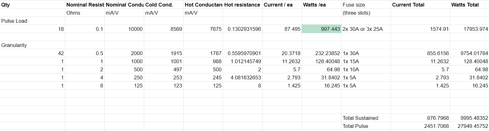
All in all, a 0.1R stage that I expected to consume 126A at 12.6V is only going to consume 87A at 11.4V after all the aforementioned losses. This all meant that if I wanted to hit my headline figures of 10kW (I kind of boxed myself by putting that in the name, didn't I?), I now needed more load stages, quite a few more.
Thus, 33x 0.5R stages are now 42x, and 16x 0.1R stages are now 18x.
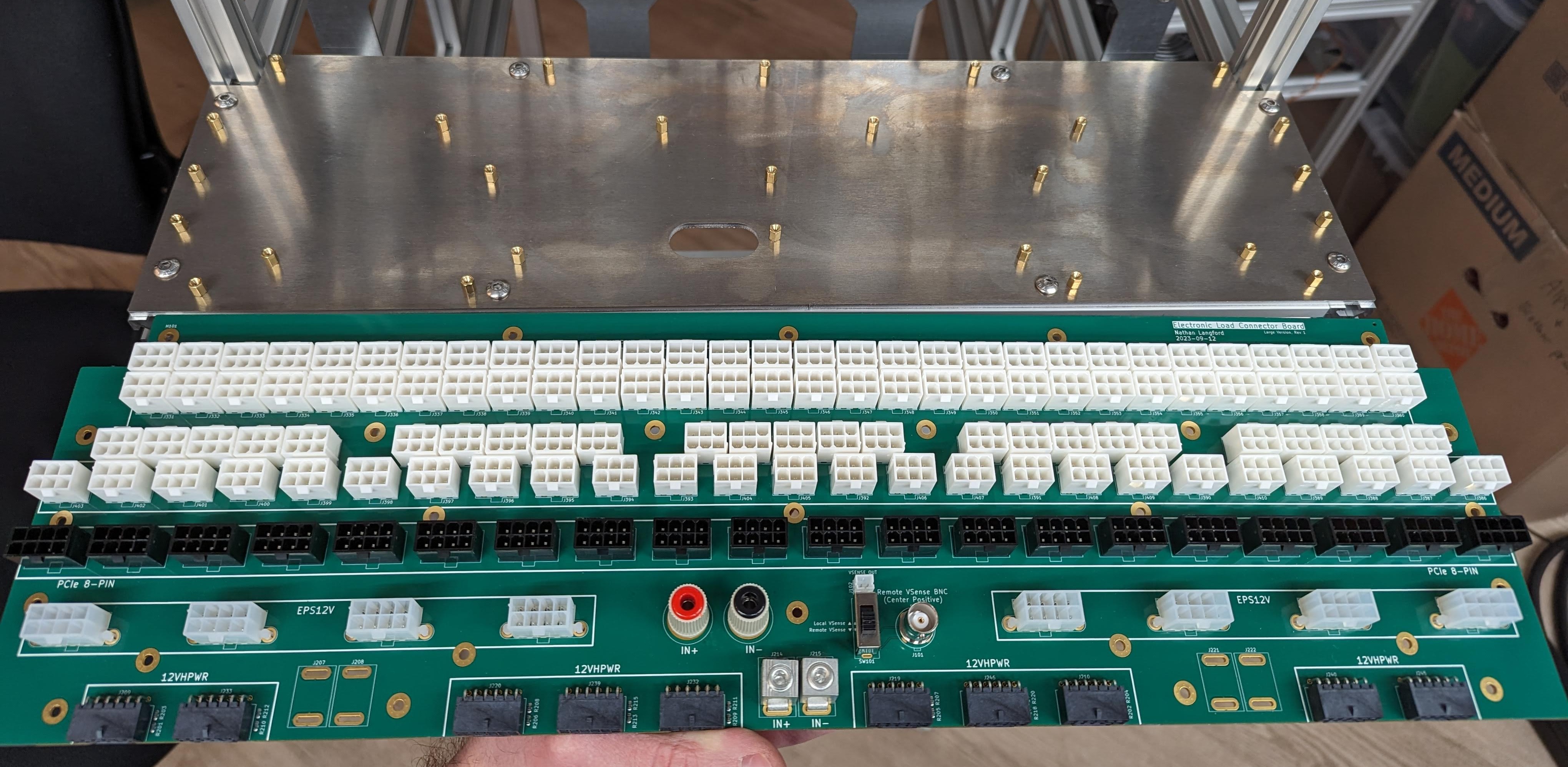
Connector PCB
The connector PCB is as boring as ever, just bigger now. It is now a 6-layer PCB with the inner layers at 2oz copper and the outer layers as 1oz. (JLCPCB couldn't do their economical assembly service the outer layers were 2oz. I don't know why, and they didn't either.). I'm also now mounting it to an aluminum plate for better rigidity, the ability to use more of the PCB due to THT pin clearance, and because getting the screws lined up with nuts in the aluminum extrusion last time was a real pain and risked damaging the board.
Also, the footprint for the binding posts is now oval shaped to perfect fit the threaded shaft with flats, without allowing rotation. Finally, there is a slight issue where the connectors are too close to each other back-to-back. Depending on the exact connector housings on the cables, the housings might interfere with each other, even if the connectors themselves are fine. You can still make it fit though but putting sideways pressure on one housing while inserting the other one.
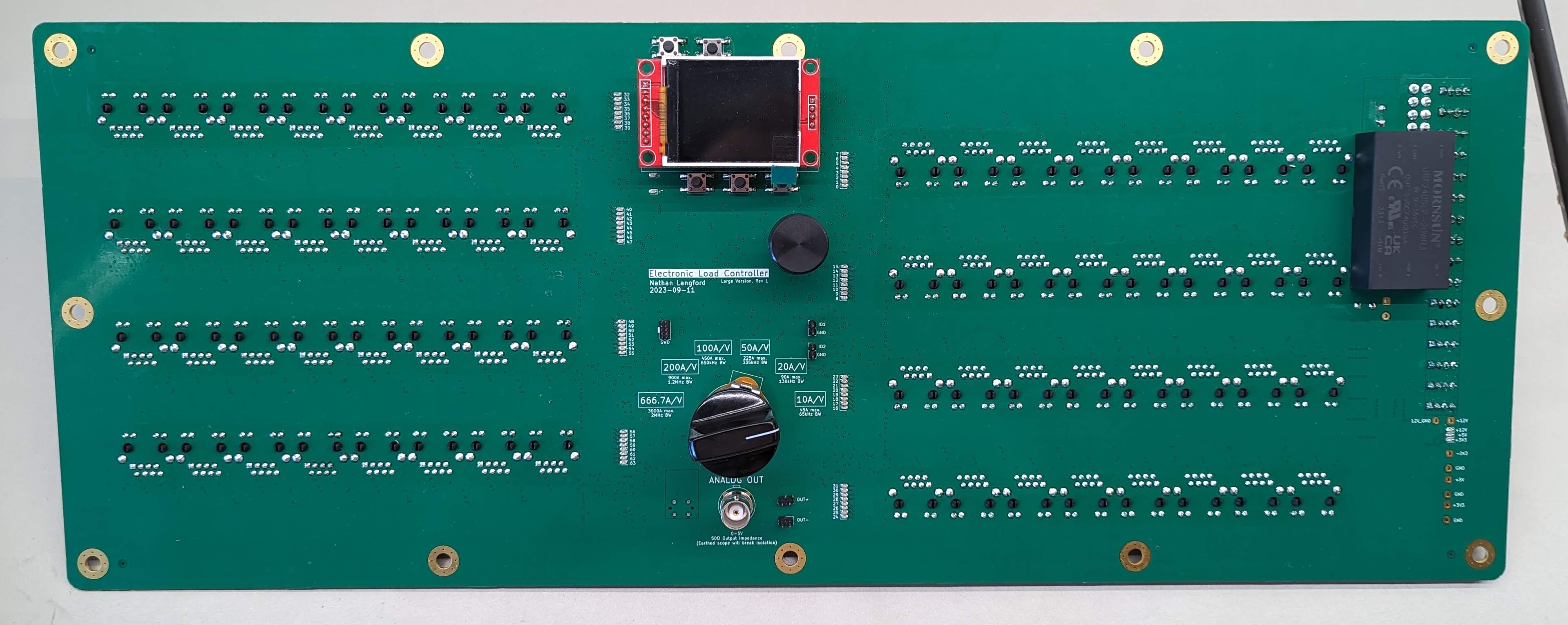
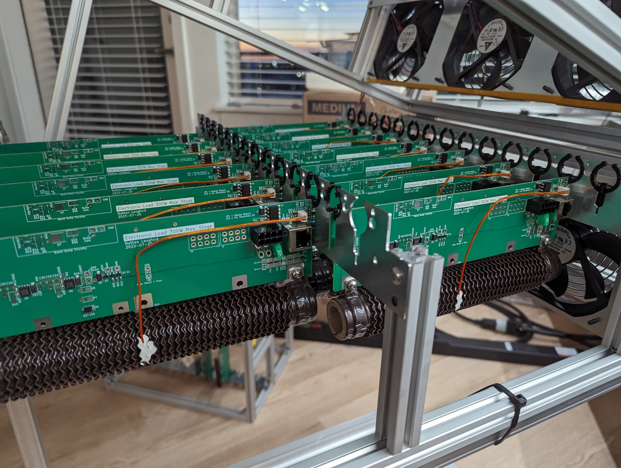
Load Stages
These are completely unchanged from the previously documented rev 2!
Cable Management
In working with the prototype, one of the biggest issues needing attention was cable management. Specifically, preventing the cables from being damaged by the sheet metal the load stages slot into.
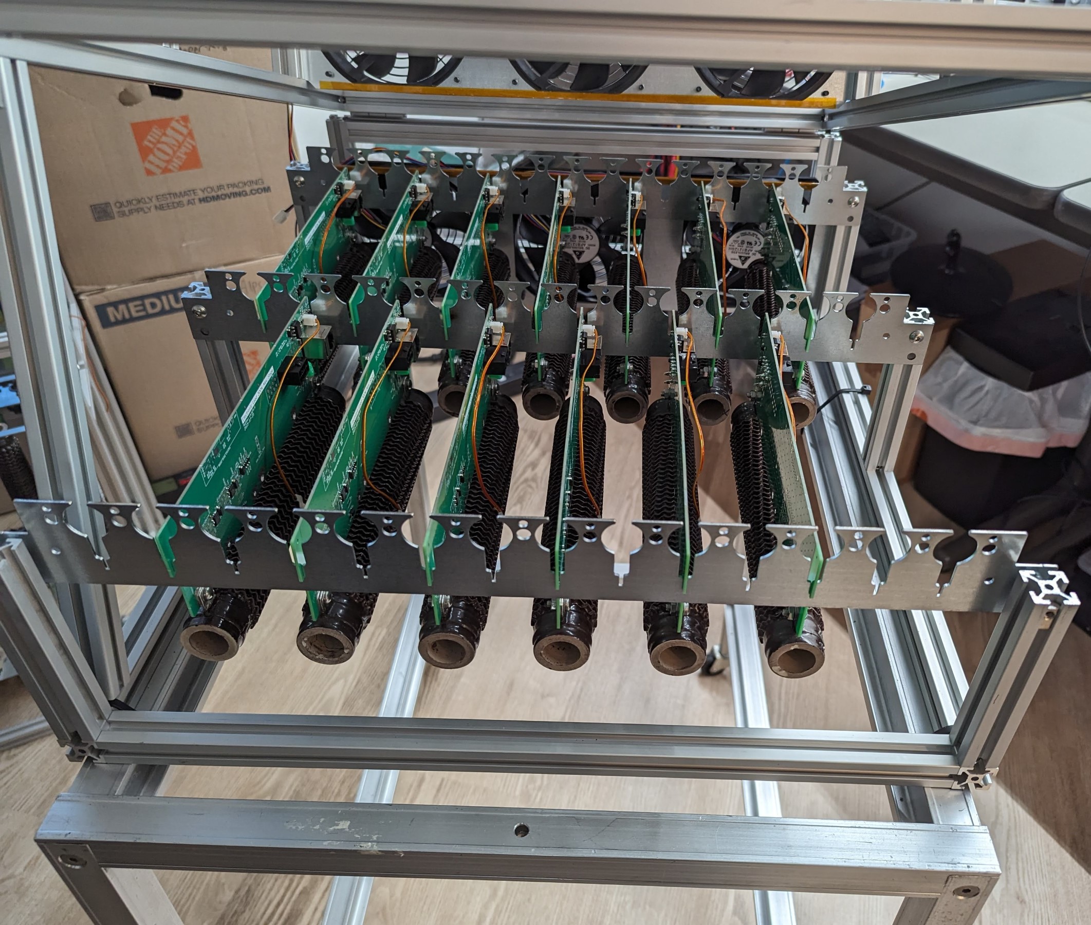
I also wasn't thrilled with the design slotting the load stages directly into the sheet metal but it technically worked, and since time was of the essence, I chose to stick with it. That's not to say it's without improvements though.
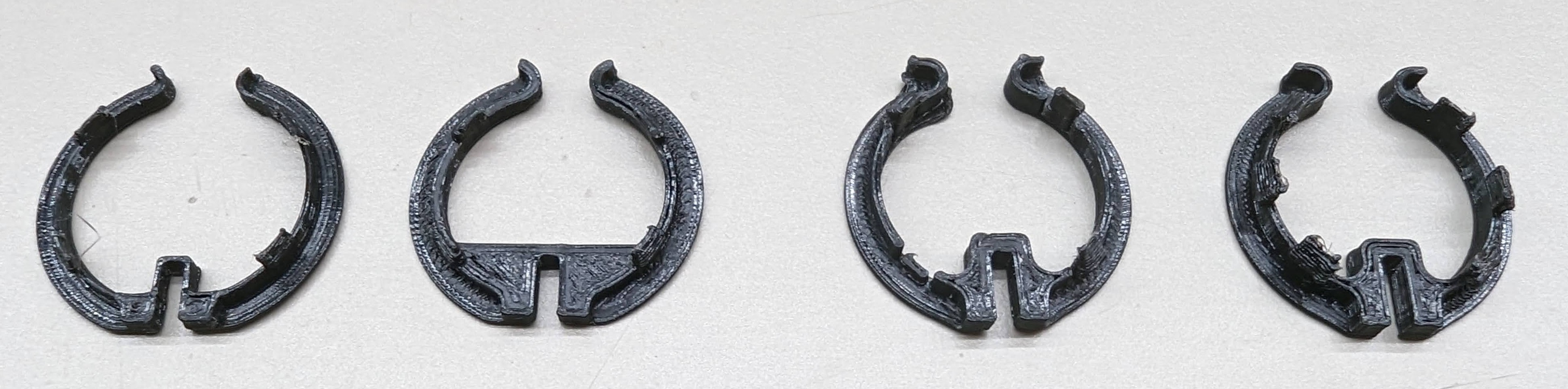
After several iterations, I came up with a 3D-printed retention clip design that works quite well.
The clips serve two purposes:
- They center the load stage PCB within the sheet metal slots and prevent the load stages from coming out. Once clipped in, they retain the load stages quite well. The system could almost be shipped like this...almost.
- They cover the interior sheet metal edges of the cable guides, preventing any metal-on-cable contact.
They are easy clip-in or remove, but while clipped in they are quite secure. They almost make the PCB in sheet metal slot design feel like a good idea.
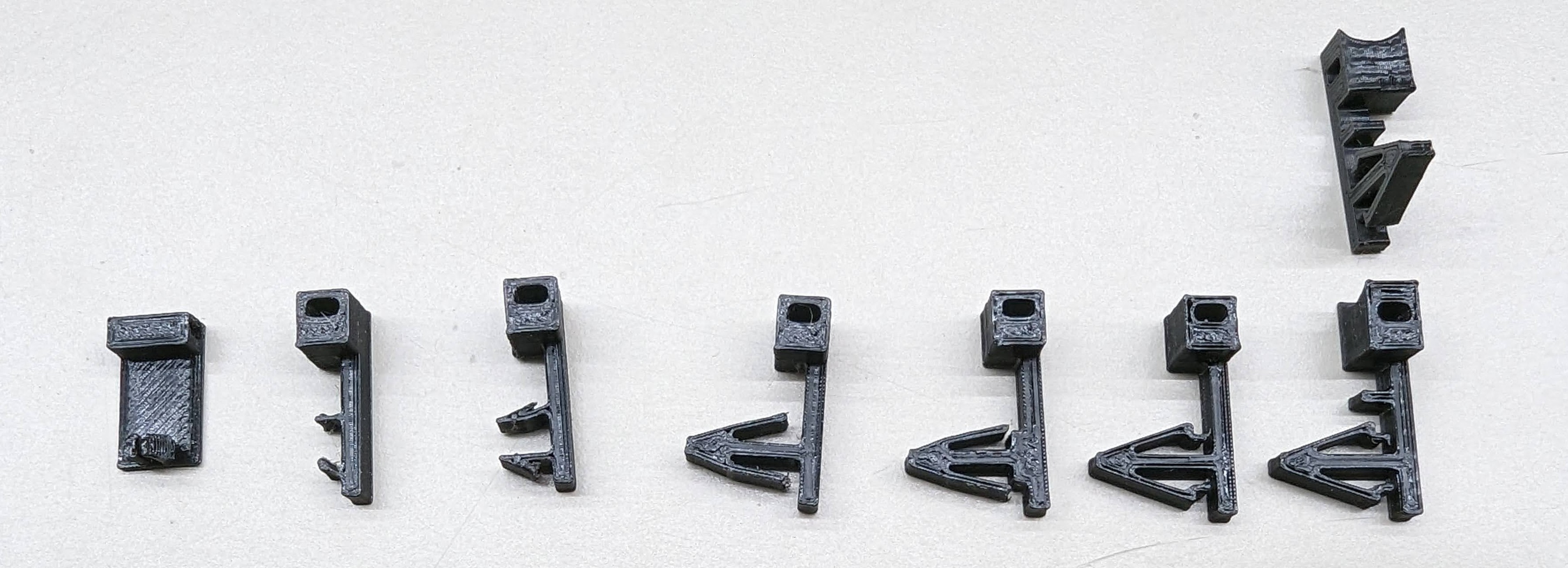
Separately, in the previous version there were notches cut in the sheet metal between the load stage slots, where I imagined the CAT6 signal cables would lay. That didn't work at all in the prototype, so I replaced them with holes that can be used for custom plastic clip-in zip tie mounts (3D printed of course). My design eventually converged on to the same design that push-in zip ties uses. As usual, I decided to learn it the hard way by coming up with my own designs, but it turns out the commercial offerings are designed that way for a reason!
Chassis Maintainability
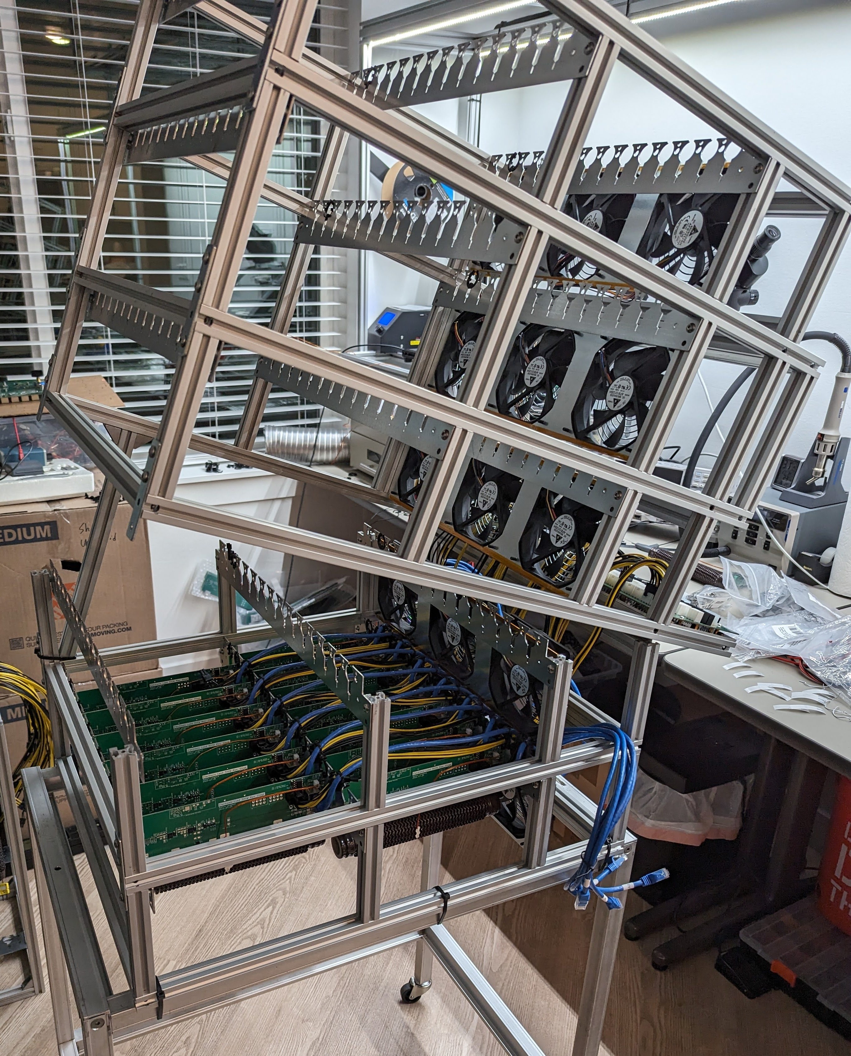
As you might have seen in some of the previous photos, the chassis has a new feature: each level can now hinge upwards to provide access to the load stages. While this doesn't make it easy, it is at least possible. Without these, I think replacing a stage on a lower level might have required disassembling most of the system. The best part about the hinge design is that due to their placement, the entire system can be hinged open without having to disconnect any cables (except for the main power cable for the control PCB).
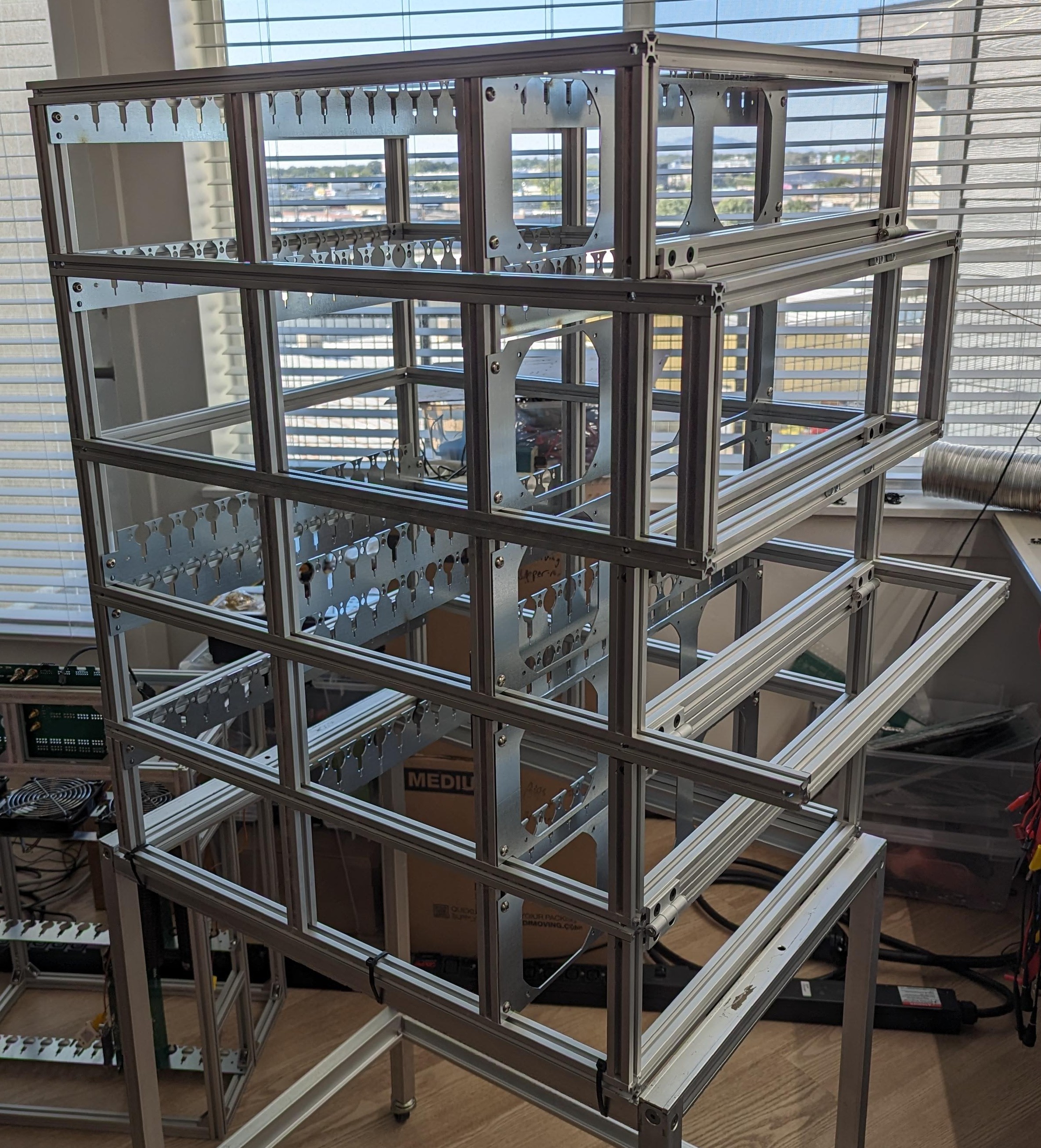
The hinges are from Miusmi and are designed for aluminum extrusion, but they weren't designed to be used like this. In the spirit of the project, I am using them in a way they weren't intended. They have no official rated load when used in this orientation. Given how heavy the entire system is now, I'd recommend caution when using these, and at the very least using three or four hinges on the lower levels that have to bear the most weight.
When opening the system like this, I have a piece of aluminum extrusion that I put in as a kind of kick-stand (or whatever the name is of the piece that holds up the hood of your car), but I bolt it into place, because if it were to fall down on you it could do some serious damage.
On the rear there are flat brackets used to secure the levels when not being hinged open.
To wrap this up, I was going to show the system in action but I'm going to put all of those photos in a separate post since this was has gotten so long, However, suffice to say, it works, and it hits 10kW.
Discussions
Become a Hackaday.io Member
Create an account to leave a comment. Already have an account? Log In.