 alnwlsn
The centerpiece of this project (at least from the operator's perspective) has to be the gauge cluster in the middle of the handlebars. It replaces the original speedometer, odometer, and timer, and provides the equivalents for generating power - volts, amps, watts (power), watt-hours (energy) and 2 stopwatches. This is also the location where I've chosen to mount the DPS5015 power supply. From the outside, it's reasonably clean looking:
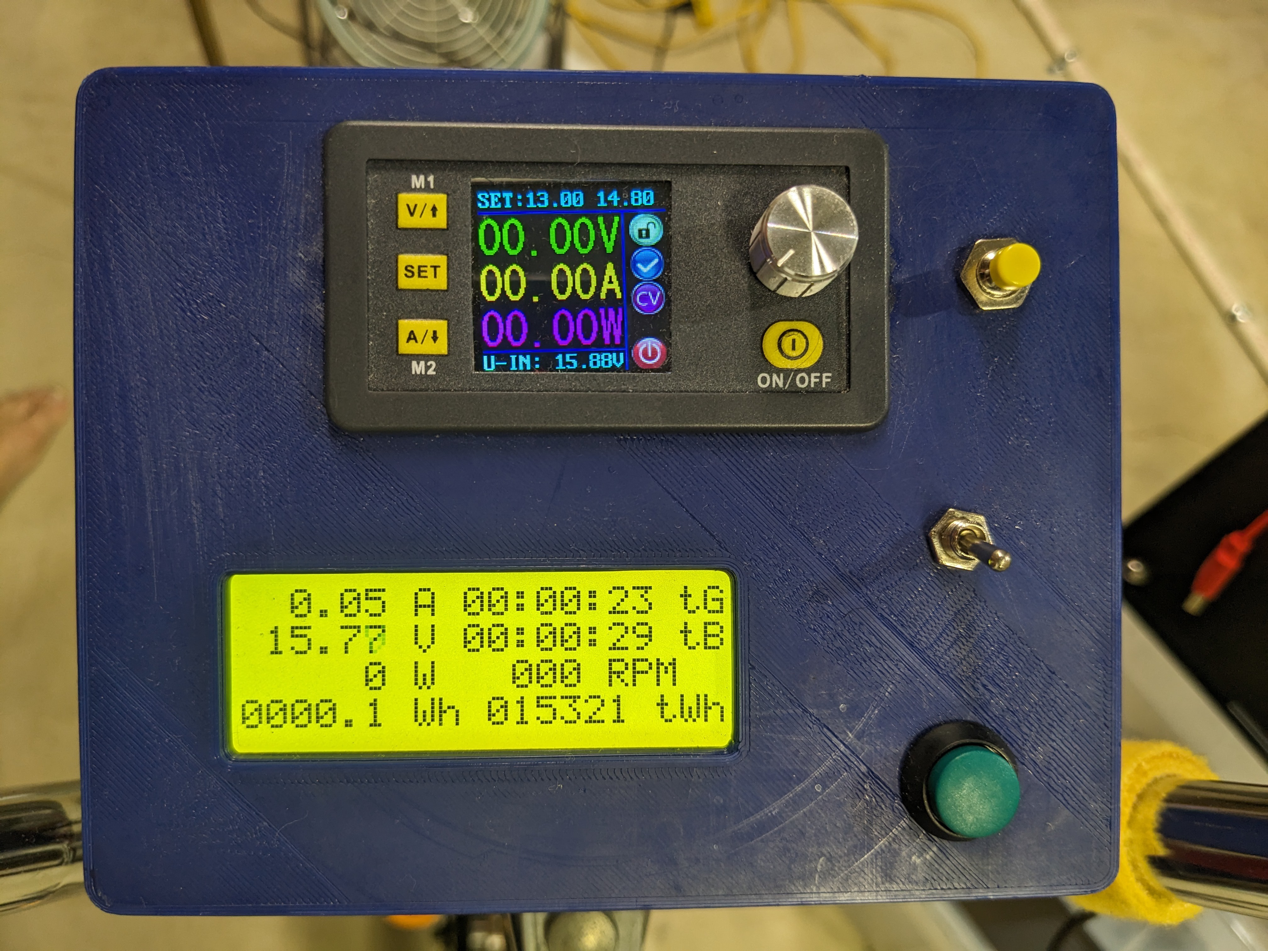
The green button is for the user stopwatch (the tB field), then we have the Arduino power toggle switch, and the yellow button is used to turn on the AC inverter. The controls for the DC power supply are similarly accessible without having to stop pedaling.
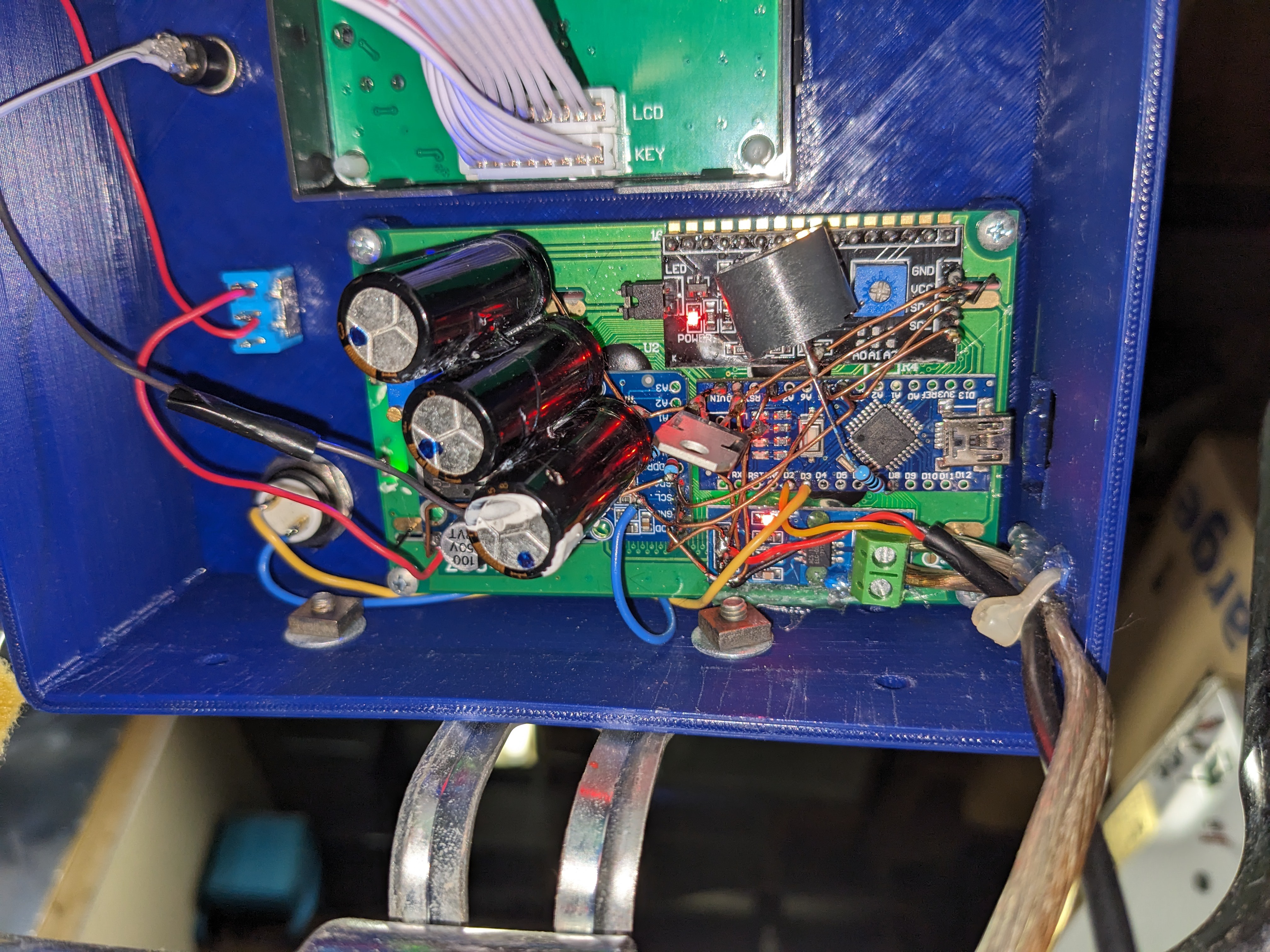
From the back, it's a messterpiece of solder and uninsulated wire (hey, as long as they don't touch, it's OK). To get a better idea, take a look at this crudely drawn schematic:
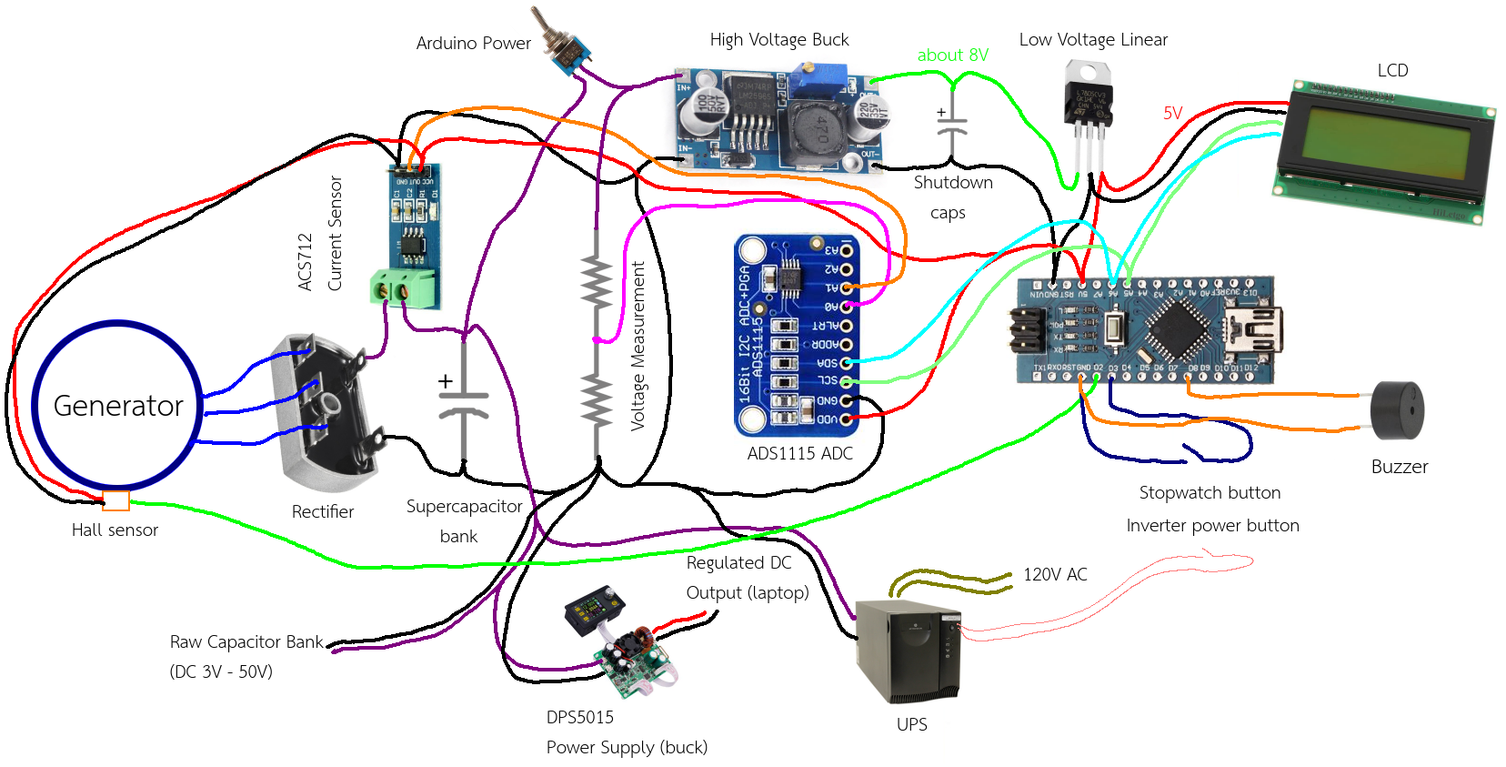
This is pretty much the entire electronics of the whole project. The rectifier and supercapacitor bank mentioned earlier are in there too, as are the previously discussed AC and DC power supplies for powering external devices. The whole thing runs on an Arduino Pro Mini, since we don't need anything too powerful.
The power is calculated from the instantaneous voltage and current. Voltage is measured with a regular voltage divider off the supercapacitor bank, and for the current, I measure it using one of those Hall effect current sensor modules. These a pretty neat; they pass a thick wire through the chip package, then measure the tiny magnetic field produced when current flows through a wire. This means that they have very low resistance, which means you do not lose power through your current meter. On the other hand, the magnetic field that they measure is so tiny, it is easily overpowered by nearby sources. In my own shop, they seemed to be affected by the earth's magnetic field. So they must be calibrated against some sort of current meter in the final setup so you can get an accurate reading in operation. The voltage divider is the same way, but is pretty much static once you figure out the scaling values to use. The sensor I used was for the 5A range, but I found that I can occasionally generate more than that when pedaling hard, which means my setup underestimates the total power a little bit sometimes, at the peaks when I push down a pedal.
Energy is of course the integral of power over time, which is done at a resolution of 40 Hz. This isn't super fast, but it's enough. The power is only measured as the output from the generator. Where it goes after that would probably be a good thing to know, so I may add a second current sensor. It is stored as an integer value internally so I don't need to worry about rounding.
I upgraded to a better ADC, since the one in the AVR is a bit low resolution, since I happened to have one.
For Arduino power, I used a cheap buck module with a very wide input range. I think most places state the max voltages of these at 37V, but I have been running the one in the bike up to 50 volts for well over a year, and it has not exploded or caught on fire yet. Don't recommend doing this, but there you go. The output from the buck supply goes into a linear regulator to provide a better quality 5V rail, so that I can run the ADC off it. BTW, the linear regulator does have the usual decoupling capacitors, I just didn't draw them.
Another feature is that the total energy is stored in EEPROM at a power loss, that way I don't have to track it manually. To allow this, I put a few scrap capacitors in the 1000uF range between the buck supply and linear regulator for the Arduino. When the measured voltage in the supercapacitor bank drops below 7 volts - the minimum dropout for the linear regulator - the Arduino knows it is about to lose power. This also happens if the power switch is flipped. The capacitors provide just enough juice for the Arduino to save the cumulative energy in the EEPROM before they run out.
There is also an RPM sensor which measures the generator RPM. This helps me get an idea of how the speed relates to the voltage, and besides, it was already there. Three hall effect sensors are internal to the motor housing, and I connected up one of them to get the RPM. These cannot be an encoder for the servo because they are far too low resolution; in my case, 2 pulses per turn. My guess is that maybe they are there to sense the initial magnet orientation at power up, so that the driver can start off at the correct phase, but I'm not completely sure.
The buzzer was included as a low power alarm for when I was running a laptop running at 20V. Once the supercapacitor bank dropped below about 19V, the alarm would start beeping, informing me that I needed to get back on the bike and resume pedaling. However, after some time I just found this annoying for those times I stepped away and forgot to turn off the Arduino power, so I eventually disabled it.
Finally, let's discuss what's actually running on the Arduino. Thanks to flowchart.fun, the diagram for this one is much neater.
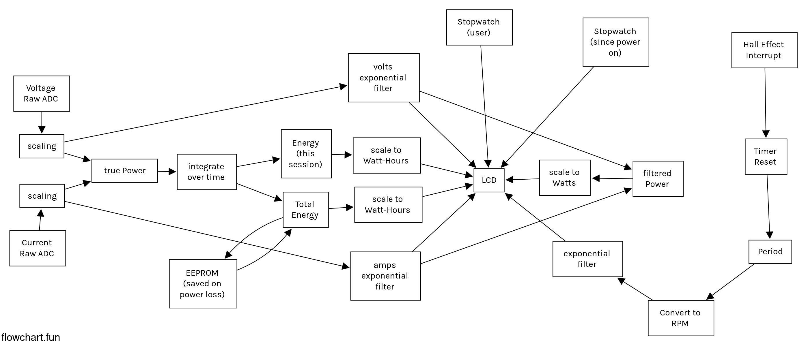
Note that power is calculated two ways, once for the energy calculation, and once to show on the LCD. This is because the raw values are very noisy, and would probably just show on the LCD as blurry black squares of which you could only tell the first digit or two. However, you need unfiltered data to integrate properly.
The power calculations and RPM meter take up 6 of the 8 spaces on the LCD, so I added 2 stopwatches. One is just a counter since the Arduino has been turned on, and the other is a user stopwatch, which I actually don't use that much. In addition, the since-power-on stopwatch only counts if the generator RPM is over some minimal value, that way you don't get time credit when the bicycle is stopped.
The last complication in the software is that the LCD is too slow to display the whole screen at once every 1/40th of a second, which is the loop time I use. To get around this, I just update one field per frame, and that has proven to work fine.
Discussions
Become a Hackaday.io Member
Create an account to leave a comment. Already have an account? Log In.