 Elijah
Smart Water Tap Leakage Controller IoT Project
Loss of water through water taps that are either left unclosed is a problem that the world has been confronted with for many years. A Smart Water Tap Leakage Controller IoT Project is a solution.
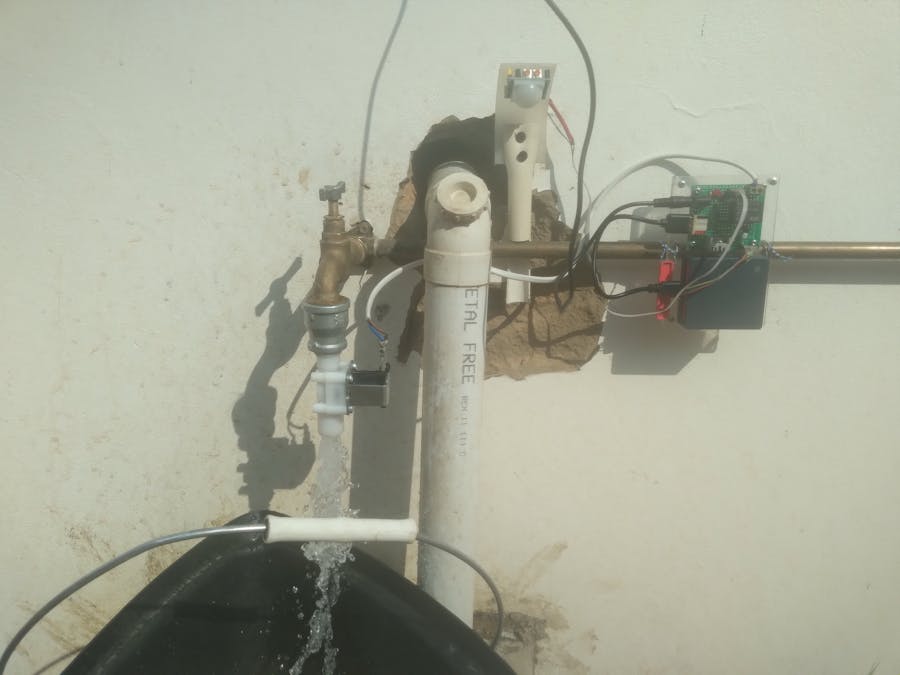
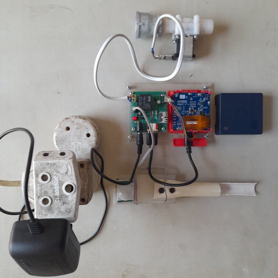
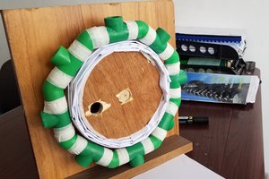
Main Project Photo
Story
Smart Water Tap Leakage Controller IoT Project
Water is a very scarce resource that needs to be used sparingly by everyone. Many people around the world go for days without this fundamental need. Many liters of water are lost through water taps that are either left unclosed or not properly closed every day, which is a concern for the world at large. Due to climate changes and other factors, we are gradually running out of underground water and the rain no longer falls as it used to do without the negative impact of climate changes. Everyone has a duty to save water and save lives. Using technology, we can make this a reality.
Demo video
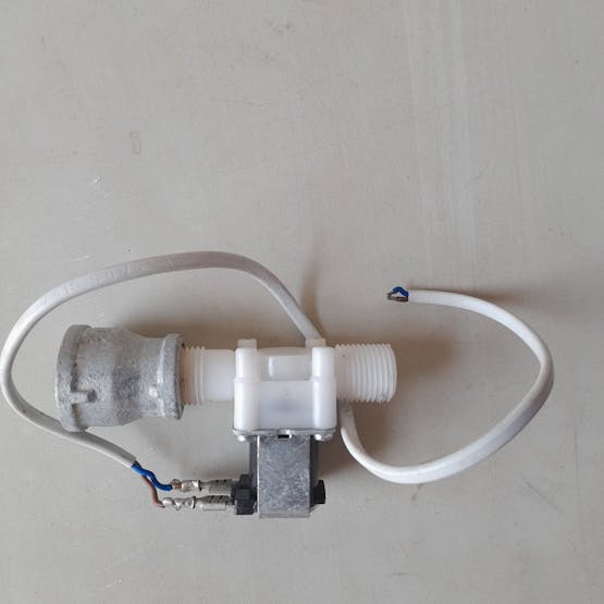
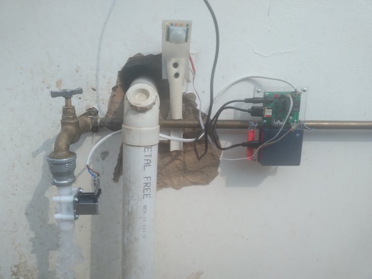
The demo video above shows how the final installation of the Smart Water Tap Leakage Controller IoT project works. The person in the video is a 30-year-old farm trainee fetching water after his launch. When he leaves the water tap open and walks away, it automatically closes the 12V water flow selenoid valve and saves water. When he comes back to the tap to fetch another cup of water, it automatically opens when the PIR motion detector sensor detects his motion near the water tap. This motion detector sensor can detect motion at an angle of 120 degrees, which I didn't want. I covered the bottom part of the sensor in order to reduce the angle so that it does not detect the motion of people passing by.
Project Planning
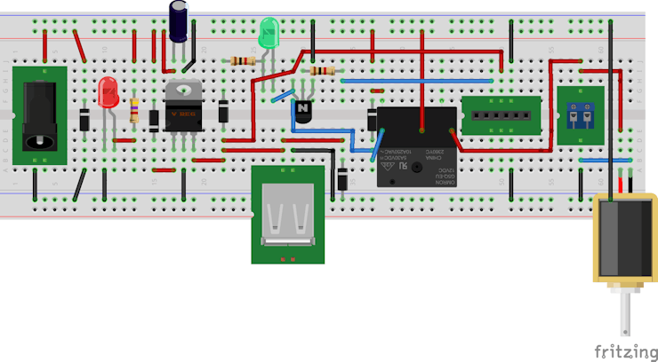
Figure 1
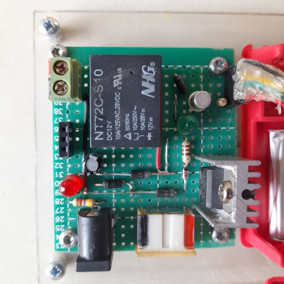
The image above (Figure 1.) shows the Fritzing Breadboard with components that I have used to build a circuit that detects the motion of people near the water tap and switches ON and OFF the 12V water flow valve. I used an 80K0960 general-purpose switching transistor to control the 12V relay. The ON and OFF states of the relay are indicated by a 5mm LED connected to the Collector of the Bipolar Junction Transistor (80K0960).
Internet of Things (IoT) and its benefits
The Internet of Things is a new technology that enables billions of connected devices to communicate with one another in many areas such as homes, cities, industries, etc. IoT is the main driving force in the Fourth Industrial Revolution (4IR). These connected devices collect sensor data such as temperature, humidity, air quality, etc., and send it to the cloud where it is stored in a secure database and analyzed to help different organizations make informed decisions. By so doing, these informed decisions minimize loss and maximize profit. The positive impact of IoT on the way people live their lives today will soon be seen in their homes. Home appliances will soon be able to communicate their states of operation and what is in the houses via the following licensed communication technologies:
1. Bluetooth Low Energy
2. Wi-Fi, Zig Bee
3. Cellular Networks
4. Unlicensed Communication Technologies like Sig Fox, etc.
Since these devices do not only use Local Wireless Communication Networks but...
Read more »


 Anteneh Gashaw
 tlankford01
 Sagnik Bhattacharya
 Uncle Toby and Aquaman