My first step is to focus on safety and power reliability. I don't actually want this thing to work if it's going to catch on fire, lol.
so I'm replacing the giant open frame 5V 60A one with something more compact and fully enclosed.

At the time of this writing, this model is now out of stock, but it looks to be the same as the one here. Heck, there's even one with more juice (15A) advertised for these very LEDs. Strongly considering picking that one up...
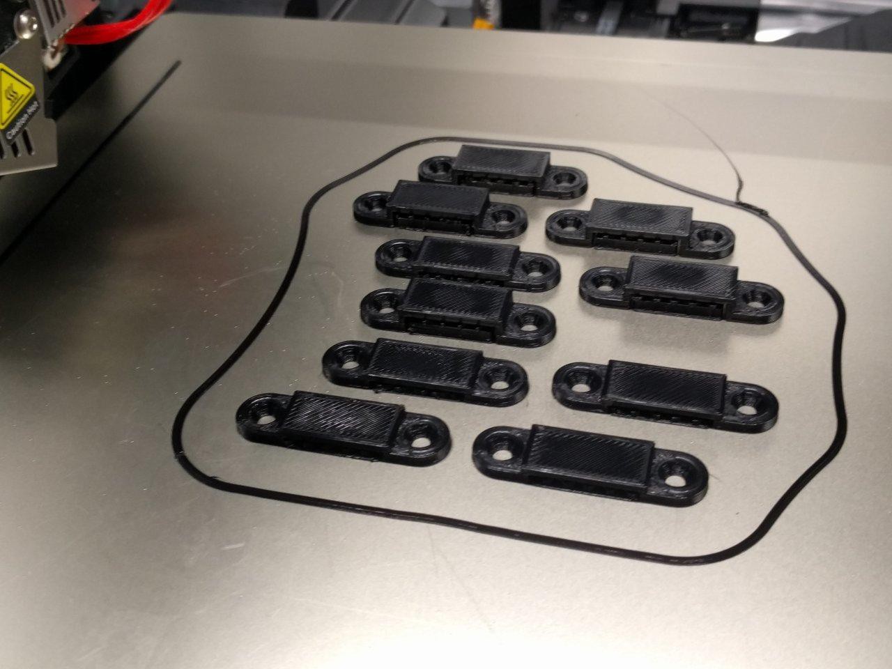
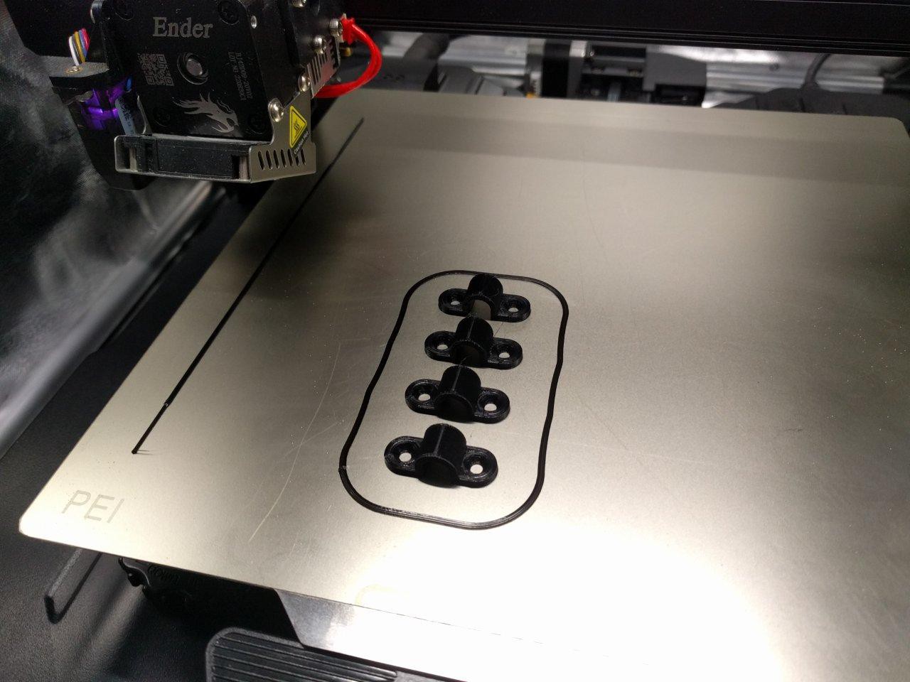
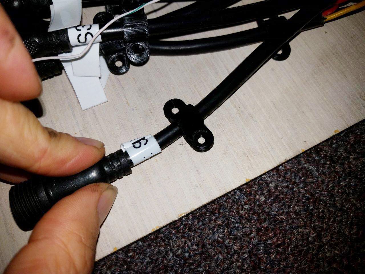
After that, it was on to modeling and printing some legitimate clamps. I certainly don't trust holding everything on with hot glue, as is the current state I received it in. Sure, I could use some kind of epoxy or foam double tape, but I'd like to have this be serviceable and have parts replaceable when needed.

There are 3x clamps here for holding in the PSU, one small clamp model for holding down the individual board output connector cables, and a flat wider clap for holding down the LED strips.
I made two wide clamp variants, 1 type that's 2mm tall and 1 type that's 4mm tall. This is to accommodate the somewhat jerry rigged installation of LED strips which have differing protuding Z heights.
The blue PSU clamp in the picture has an extra cutout for the power LED.


Everything printed out great, and I'm confident these will be usable on a first iteration. I did some minor tweaks to my countersunk M3 holecut model and it works perfect now :)
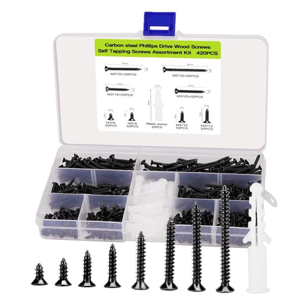
They are all designed to work with these screws:

Note, the models did not include the full AC power plug width, so some minor rotary drilling will be needed for two clamps. no biggie. I also need to sand / drill off the nubs underneath the power supply for a flush fit. The radius for the corners fits perfectly at 6mm, using my trusty 3D printed fillet gauge from the wonderful @Matt_DatumCAD :)

[To be continued...]
 CriptasticHacker
Discussions
Become a Hackaday.io Member
Create an account to leave a comment. Already have an account? Log In.