I started this project quite a while ago, initially as an add-on for the RC2014 RP2040 board (which exposes more RP2040 GPIO than the Pi Pico does). But I was never quite committed to it, partly because it adds a microcontroller to a retro-style computer and partly because I still didn't have enough GPIO to fully implement the functionality of the TMS video chip.
Enter the PicoDVI project which is perhaps more convenient these days than VGA, as well as using far fewer of the RP2040's GPIO (VGA output uses loads).
I've had the Pimoroni DVI playground board for some time but haven't put the time into trying it out properly, until now.
It took some time to get to the point where I had my own project running using the PicoDVI library, and could generate my own display.
Once I'd reached that point, then this project has fallen into place very quickly.
(The moir effect here isn't visible in real life and the blue is closer to the TMS chip's dark blue - IRL it looks extremely good.)
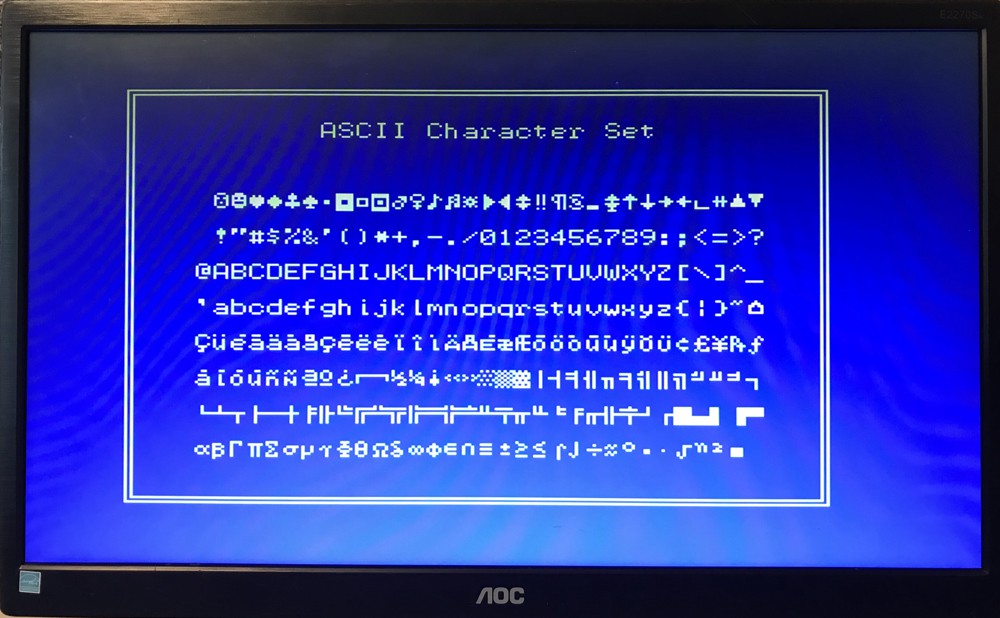
Getting the 40-column text mode running was pretty simple, it uses two colours and I have plenty of breathing room within a 320x240 display and 8-bit colour. The TMS chip's resolution is only 255px x 192px, which means we have an empty coloured border as per the TMS chip.
I'd heard that the PicoDVI was memory and CPU hungry, but what I'm doing here doesn't seem to be making it sweat.
By connecting the RC2014 serial lines to the RP2040's UART, we can receive the characters from the RC2014 serial output (and later send characters from a USB keyboard connected to the RP2040).
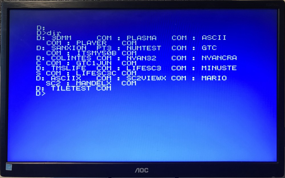
Here I'm using CP/M as my operating system, which gives serial output. We're still using the TMS 40-column 2-colour text mode. Using this is much like Picoterm colour (though I don't intend to fully implement the terminal functionality - this is more about the TMS emulation, less about terminal emulation). 80-columns would be better and I think I can do that by adding a mode (perhaps close to MSX2's 'screen 0'). That's for another day and is on the 'nice to have' list.
One other little note, when you use a TMS chip, the first thing you do is to set up pointers to your tables in VRAM and send in character bitmap data (if you want text). Obviously in order to make this work on startup with the RC2014 serial output, I've put in some default table pointer values and a 6-bit font.
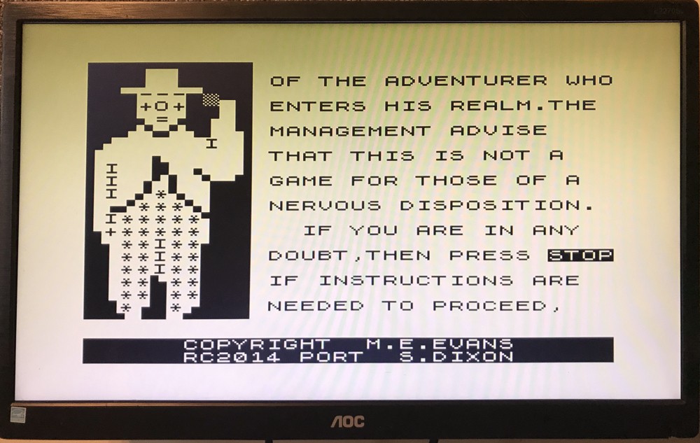
From here, adding TMS Graphics Mode 1 (aka 'tile mode', or 'screen 1') was very quick. The characters go to 8 bits wide but only 32 columns. The colour is a bit limited, but a bit better than the text mode's two colours on the screen. My 3D Monster Maze port for RC2014 uses this mode, and here it is running on my work-in-progress TMS emulator (it runs perfectly):
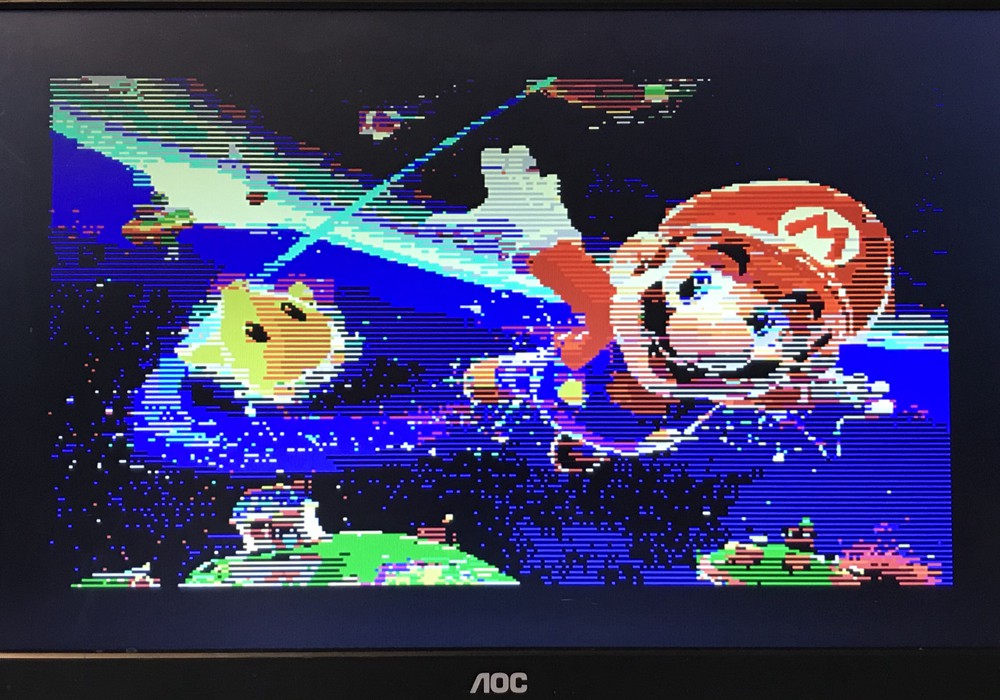
The next logical step is Graphics Mode 2 or 'Screen 2'. This is a bitmap mode that allows two of the 16 colours per 8x1 block. I have a number of .sc2 images designed for display on the TMS chip and have written a SC2VIEW.COM for RC2014 which displays them if you have a TMS video card in place. This is one of them:
This gave me a lot more trouble. I've spent hours puzzling over why I couldn't make this work and it turns out that it's something not documented (at least not in the TMS9918A reference documents that I have).
It relates to two of the TMS registers for the location of the pattern generator table and colour table (registers 3 and 4). These 8-bit values are multiplied by $800 and $40 respectively to get pointers to the tables in VRAM.
Programs that use graphics mode 2 appeared to send bizarre values for these registers. Eventually I read J B Langston's library and found these comments in tms.asm:
; set up color table at 0H (register = 7FH) or 2000H (register = 0FFH)
; set up pattern table at 0H (register = 3) or 2000H (register = 7)
It turns out that this is the explanation. In this particular mode, registers 3 and 4 work differently and in each case, only a single bit indicates $0000 or $2000. Armed with this information I was able to find confirmation of this online, but only in a document that someone had written relatively recently.
Anyway - I'm very pleased to get this mode running and see Mario looking very sharp there on an HDMI screen. (credit: there is a large collection of MSX .sc2 images at https://tomseditor.com)
We still have the full colour (but lower res) mode and sprites to go. There are also one or two very minor glitches to sort along the way.
Hardware-wise, I've switched to a RP2040 DVI feather. The reason is that it has the DVI socket built-in, and although it doesn't have as many pins exposed as the Pi Pico, there are enough for this. Plus it's not green!
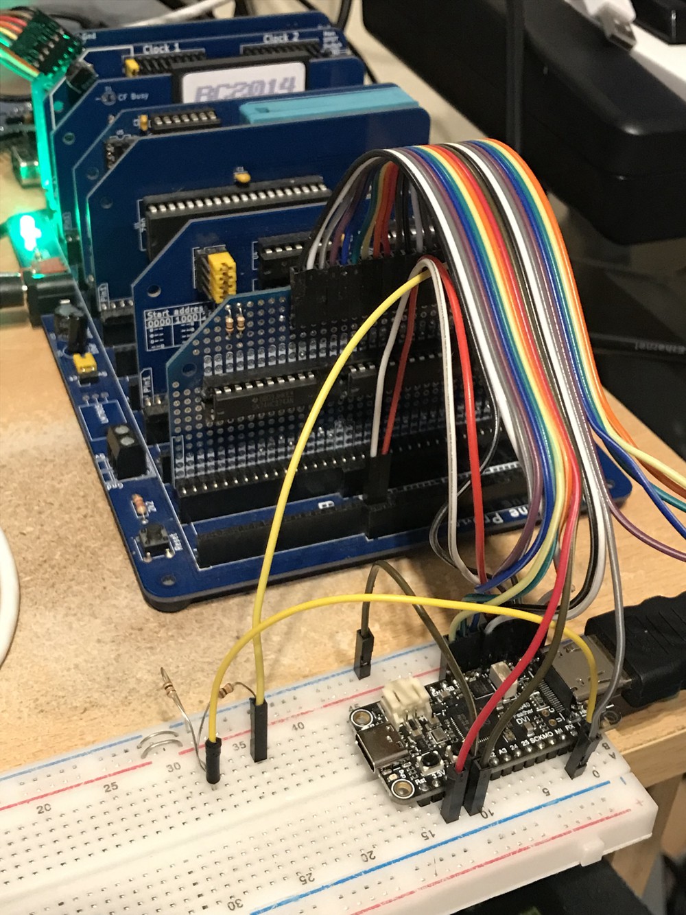
The prototype module in the RC2014 is doing the address decoding (you communicate with the TMS chip via harware ports, which is waaaaaaaay quicker than over serial), some level shifting and other things. I've already designed a board that puts all of this and the feather onto an RC2014 module (will look very cool in black). With that board I've added more logic and it *should* be possible to read the TMS status register, which I haven't implemented on this prototype yet but is important for running some of the demos.
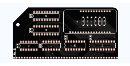
I am thinking of eventually making this my first project for surface-mounted-RP2040-on-my-own-board project, which will look much better than using the Feather.
Over and out for now.
Discussions
Become a Hackaday.io Member
Create an account to leave a comment. Already have an account? Log In.