 Sebastian
In this post I want to share how I selected a suitable topology for the resistor network that will be the core of the programmable decade resistor. Although I did some online “research”, the following criteria determined my choices:
- Switch selection: The switches shall be operated electrically. Solid state switches are great for many applications, but tend to have undesired characteristics. In this case, electromagnetic (signal) relays are a logical choice, because they provide
- isolation between the control circuit and the external application circuit,
- a fairly low contact resistance and drift over temperature and
- reasonably high current switching and carrying capabilities
- while maintaining low leakage currents.
- Accuracy: Each relay contact in the signal path will introduce an additional resistance (and potentially thermal EMF issues, that I won’t consider here). This is a good reason to minimize the number of switches in the signal path considering all resistance values of the decade resistor. Besides that it might be desireable to keep the number of relays in the signal path as constant as possible so that the variation of the error caused by the relays is better controlled.
- Cost: Relays mostly have a very limited number of poles and throws. Therefore the number of relays required will be rather high and quality relays are expensive. The topology should therefore minimize the total number of switches required. Also, the cost of precision resistors depend on the required resistance of the resistor and quantity per value.
- Parts availability: The availability of precision resistors with the specified resistance values and other characteristics is critical.
There are many more aspects that could have been considered in greater detail (like frequency response). However, the criteria mentioned above helped me to disregard some topologies and focus on the two that I describe below. To make my life easier, I will use the resistance values required for the decade n = 0 that provides the resistance values 0 Ω, 1⋅10^n Ω to 9⋅10^n Ω. The reader may apply a different n as well.
Topology A
Topology A
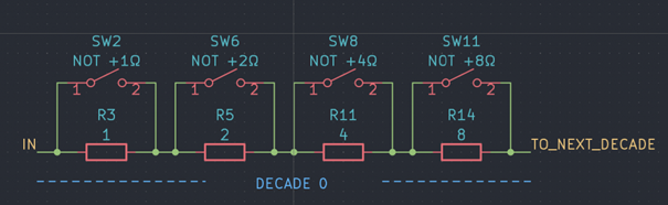
This variant uses four resistors connected in series, with 1 Ω, 2 Ω, 3 Ω and 4 Ω of resistance respectively. Each resistor can be shorted with a switch, hence presenting 16 valid switch combinations/resistance values. In practice, five or six of those combinations could remain mostly unused: 10 Ω, 11 Ω to 15 Ω. It’s worth noting that with these switches alone it is not possible to open the circuit, hence increasing the total number of relays in a multi-decade resistor by one if that feature is called for.
Although this approach minimizes the total number of switches, the number of switches in the signal path can become relatively high. The worst case situation would be a short: For a 6-decade resistor the minimum resistance would roughly equal the contact resistances of 24 relays (or 25 if you count the additional breaker) connected in series, though each in parallel to the respective shorted resistor. Depending on the contact resistance of the switches this introduces an error that might be unacceptable for some applications, especially for decade(s) with generally low resistance values. Maybe worse – the additional contact resistance may vary with the selected resistance value: For example, to select 7Ω, exactly one switch is closed (SW 11). In contrast, only closing all four switches will short the decade.
Although it would be fine to (at least) use this topology for the upper decades I wanted to keep all decades the same. With the disadvantages described above, I decided against using this topology at all.
Topology B
Topology B
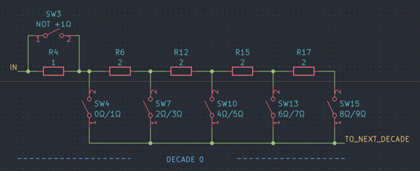
In variant B a total of five resistors (1 Ω, 4x 2 Ω) are connected in series, complemented by six switches. Closing one of the five switches SW4, SW7, SW10, SW13 and SW15 while switch SW3 is closed selects 0 Ω, 2 Ω, 4 Ω, 6 Ω and 8 Ω of resistance respectively. Leaving SW3 open instead adds 1 Ω to these values.
This topology requires six switches per decade – two more than variant A – and five instead of four resistors. But now, only either one (for odd resistance values) or two (for even resistance values) switches are in the signal path, reducing the maximum total contact resistance by a factor of 2. Not only that, the (maximum) variation of the contact resistance is lowered as well. A separate “breaker” to open the circuit is not required.
As a side note: My "vintage" Siemens decade resistor box that I bought not too long ago uses this exact topology as I discovered after designing the device. However, because of the fancy rotary switches, the schematic looks way more complicated…
Next steps
In the next post I’ll highlight (very) simple, but effective optimization opportunities that will make the implementation (not only) more cost-efficient. Closely related to this: The power rating of the decade resistor.
Discussions
Become a Hackaday.io Member
Create an account to leave a comment. Already have an account? Log In.