 Sebastian
The following block diagram provides an overview of the different circuit groups of each functional block, their internal connections and external interfaces.
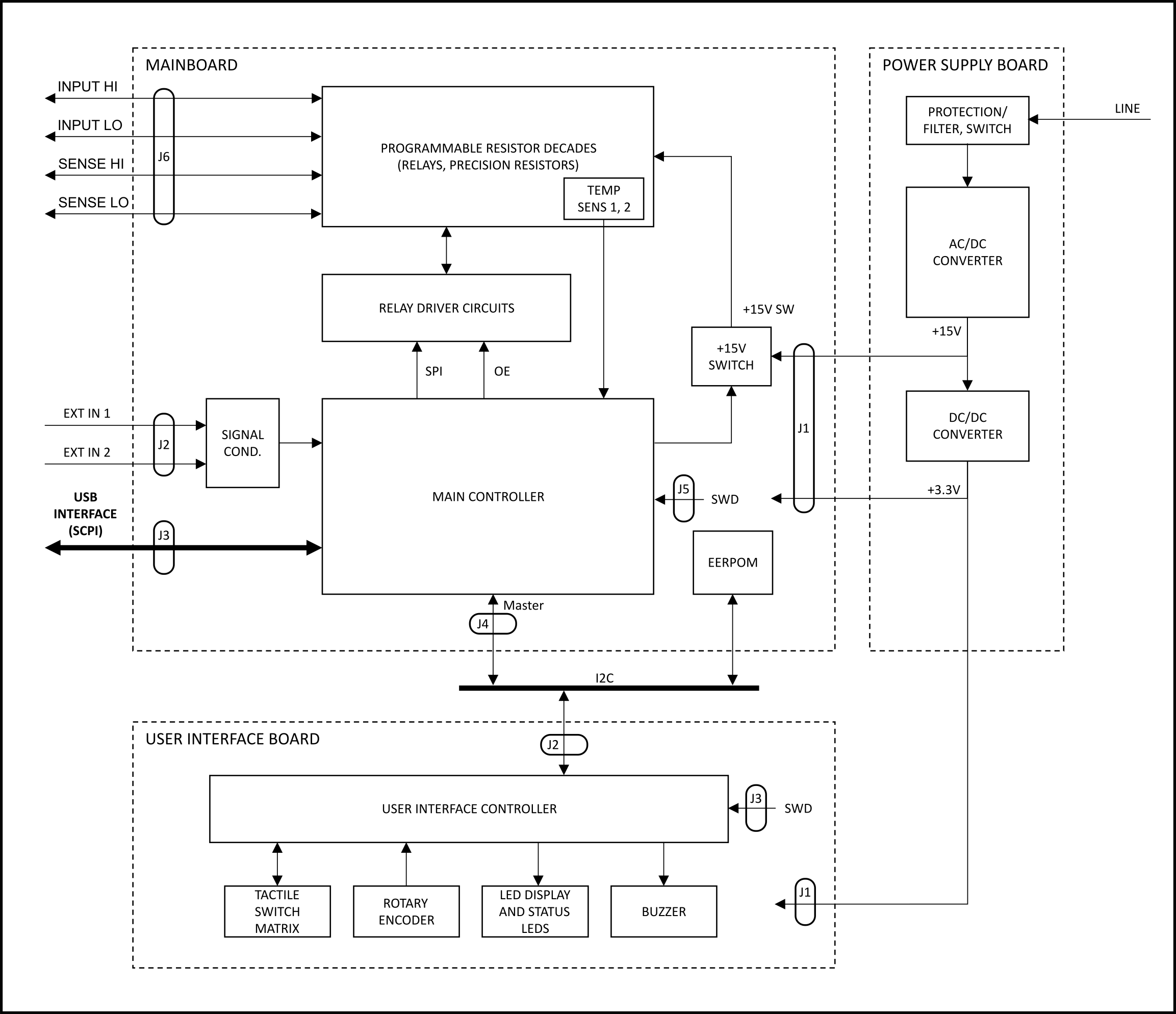
Block diagram of the programmable decade resistor
The Programmable Decade Resistor consists of three main functional blocks:
- Power supply (Power Supply Board)
- Programmable decades, control and driver circuits (Mainboard)
- User Interface (User Interface Board)
The power supply board uses an off-the-shelve AC/DC converter to provide a +15V rail. The +15V rail powers the relays on the mainboard as well as a DC/DC converter. A single DC/DC converter generates a +3.3V supply for both the mainboard and the UI board, including the LED display. The power rails are earth-referenced. (Nevertheless, the inputs of the Programmable Decade Resistor are floating thanks to the isolation provided by the relays.)
The mainboard’s main controller contains the business logic to control the relays, read the external inputs and run the USB and user interfaces. The main controller communicates with the User Interface Board over I2C which handles the multiplexing of the alphanumeric LED display, scans the switch matrix, decodes the signals of the rotary encoder and drives the buzzer.
Next steps
The next post in this series takes a more detailed look at the mainboard.
Discussions
Become a Hackaday.io Member
Create an account to leave a comment. Already have an account? Log In.