 Aaed Musa
Design
The single-leg design hasn't changed much. I cut off a bit more weight and removed the homing block. This homing block will now be a separate part incorporated into the actual robot design rather than on each leg itself.
The approach that I took to designing the test legs was to have the actuators connect together and make up the main body of the leg. This worked well for a single leg, so I'm applying that same design strategy to the full robot assembly.
The frame of the robot is made up of 4 carbon fiber tubes. Each of the legs slides onto two of the carbon fiber tubes. The front, back, and middle of the robot have panels to hold the 4 tubes in place,
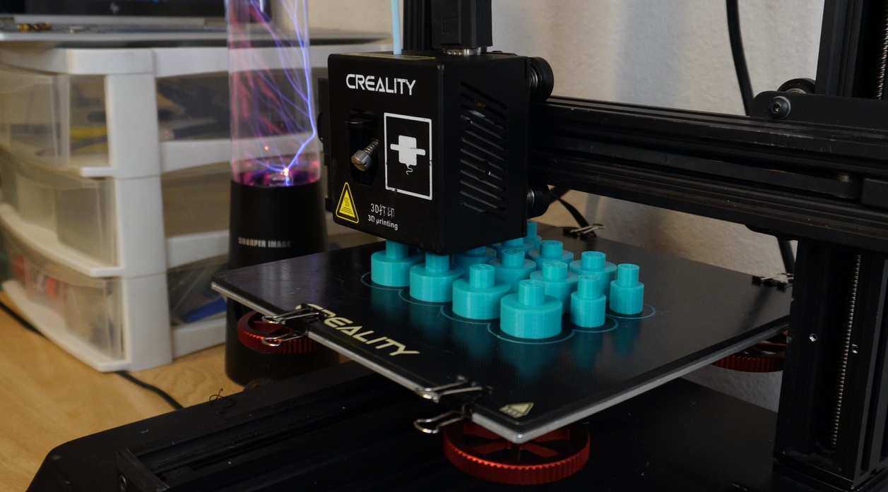
One of my main design considerations was making all of the parts small enough to fit on a 200 x 200 x 200mm print bed.
Previously I had just 3D printed the feet on the test legs, but 3D-printed feet have little to no traction. For the full robot, the feet were cast in 30 A silicone which, according to online scales, is somewhere between the squishiness of a rubber band and an eraser. The base of the foot is 3D printed, so the silicone is just applied to the outside of this base. I did this by suspending the part in between two 3D-printed molds and pouring silicone inside.
Printing
It took about 3 weeks to print all of the parts on my reality CP-01 printer. Overall the 3D printed parts account for 9.98lbs (4.53kg) which is about 1/3 of the robot's weight. I printed all of the parts in black and Bahama blue PLA.
Build
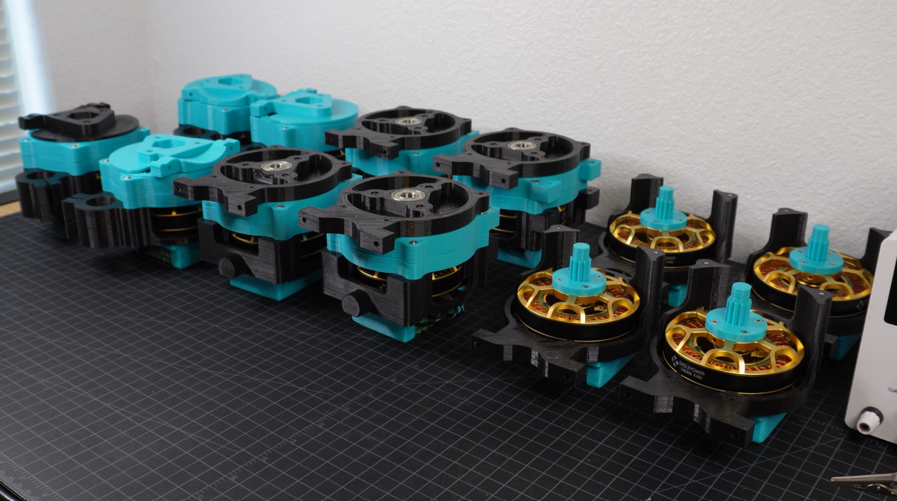
The first step in assembling the robot was to build all 12 actuators using 12x high-torque 90KV brushless motors and 12x ODrive S1 brushless motor controllers with position, velocity, and torque closed-loop control.
To get the actuators up and running, I used the ODrive GUI to change settings, calibrate the motors, and define each actuator's CAN bus node ID.
There are 3 different types of actuators since each leg has 3 types of joints: adduction, hip, and knee. These each fit together to form the body of a single-leg assembly and 4 of these leg assemblies form one 12 DOF robot.
In my single-leg testing, I found that using screws with carbon fiber tubes ended up just making wide and unusable holes. To fix this, I integrated clamps into the design of each adduction actuator’s housing so that I could use a screw to clasp the actuator onto the carbon fiber tube.
Electronics
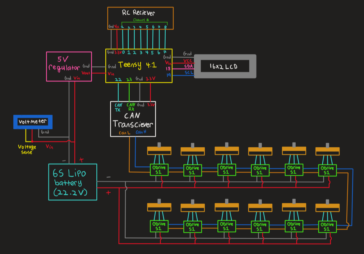
All 12 of the actuators are powered by a 6S 5200 mAh Lipo battery. The actuators are also Daisy chained together via the CAN LOW and CAN HIGH lines which connect to the CAN bus transceiver which connects to the Tensy 4.1 microcontroller.
I'm using an RC remote and receiver to control the robot as well as a small 16x2 LCD to act as a menu for different control modes. Both of these also connect to the Teensy. The Teensy is powered by a 5V regulator which steps down the battery voltage. On the left side of the robot, I've attached a voltage display to monitor the battery life.
Programming
Programming this robot was the hardest part of the build. There are so many different variables to consider like the amount of time each leg is off the ground, how far the legs lift off the ground, how big each step is, the step trajectory etc.... These factors not only determine if the robot can walk in the first place, but how dynamic that walking motion is.
The main principle in getting a quadruped to walk is to always have a pair of 2 diagonal feet in contact with the ground at any given moment, this is otherwise known as trotting, and it's what allows TOPS to maintain balance.
I had originally planned for a sinusoidal step trajectory, but it just didn’t work out so I reverted to a more crude but reliable square-step trajectory. Here the foot moves up, forward, down, and back.

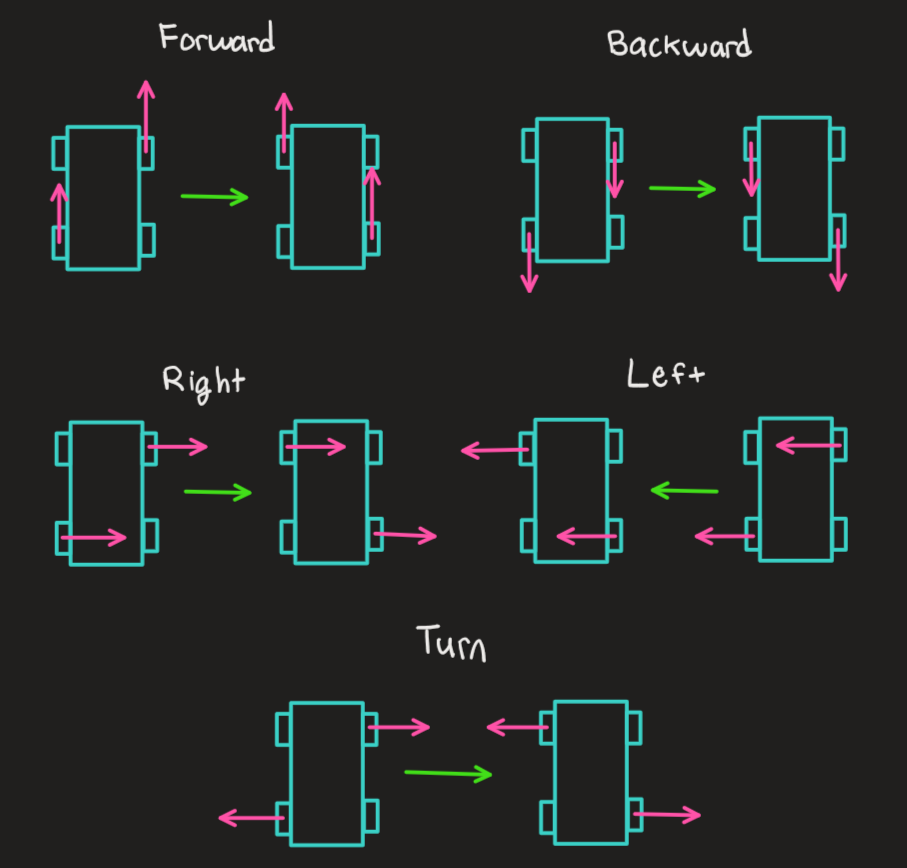
Now getting the robot to trot forward is essentially a 2-step sequence. You first need to have two diagonal feet take a step and as soon as they touch the ground, have the two other diagonal feet also take a step. If you keep the same sequence but have the feet move backwards, then the robot moves backwards. If instead of backwards you move the feet right or left then you get the robot to move sideways. The only motion that may not be as intuitive is turning. Here you actually want diagonal feet to move in opposite directions.
Overall Assessment
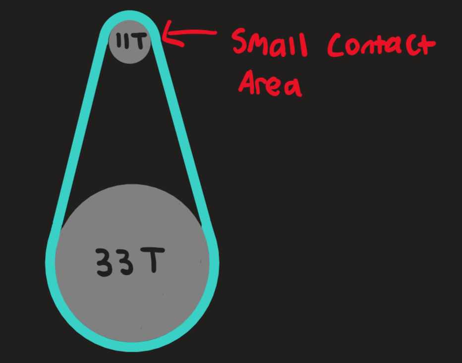
There are so many hardware and software issues that I almost considered not finishing this project at all. The main limitation on the mechanical side is that the knee joints skip like crazy and this is mainly because I’m using small 11 tooth pulleys to create that 9:1 reduction which means that the contact area for the belt is really small. Because of this, the robot can’t do things like jump or take a hard step because when the belts do in fact skip I have to recalibrate the robot.
Moving on to software issues, I have to manually calibrate each leg on startup which gets really annoying really fast. The other software issue was just a lack of natural dynamic motion. Programming gait sequences is really hard, and my code was pretty minimalistic. I also didn’t use any IMU sensors so apart from the natural compliance with the actuators, TOPS isn’t really reacting to changes in the environment or external forces. I hope to fix all of these issues in TOPS V2 which I’ll be making sometime in the future.
Discussions
Become a Hackaday.io Member
Create an account to leave a comment. Already have an account? Log In.