// Introduction
I wanted to build a compact handheld computer to play around with the Linux command line. It should be small enough to be held comfortably. While it doesn't need to be rugged, it shouldn't fall apart. It should require minimal configuration to work, so I don't have to be afraid of bricking the Linux setup and having to start from scratch.
// Features
- Works as a handheld Linux computer or as a UART terminal
- The NanoPi Neo Air and the terminal can be switched on and off independently
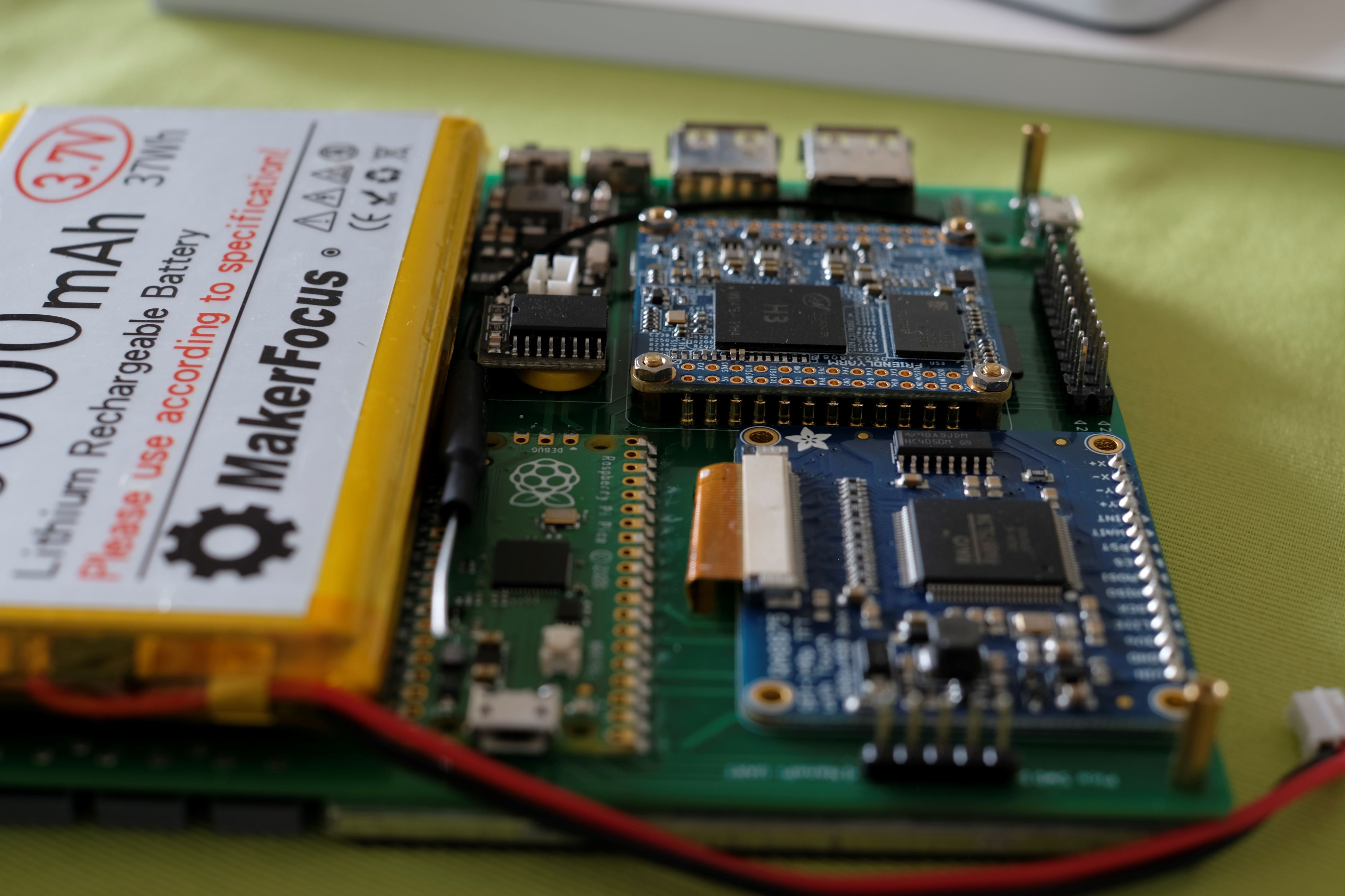
- The NanoPi Neo Air is removable
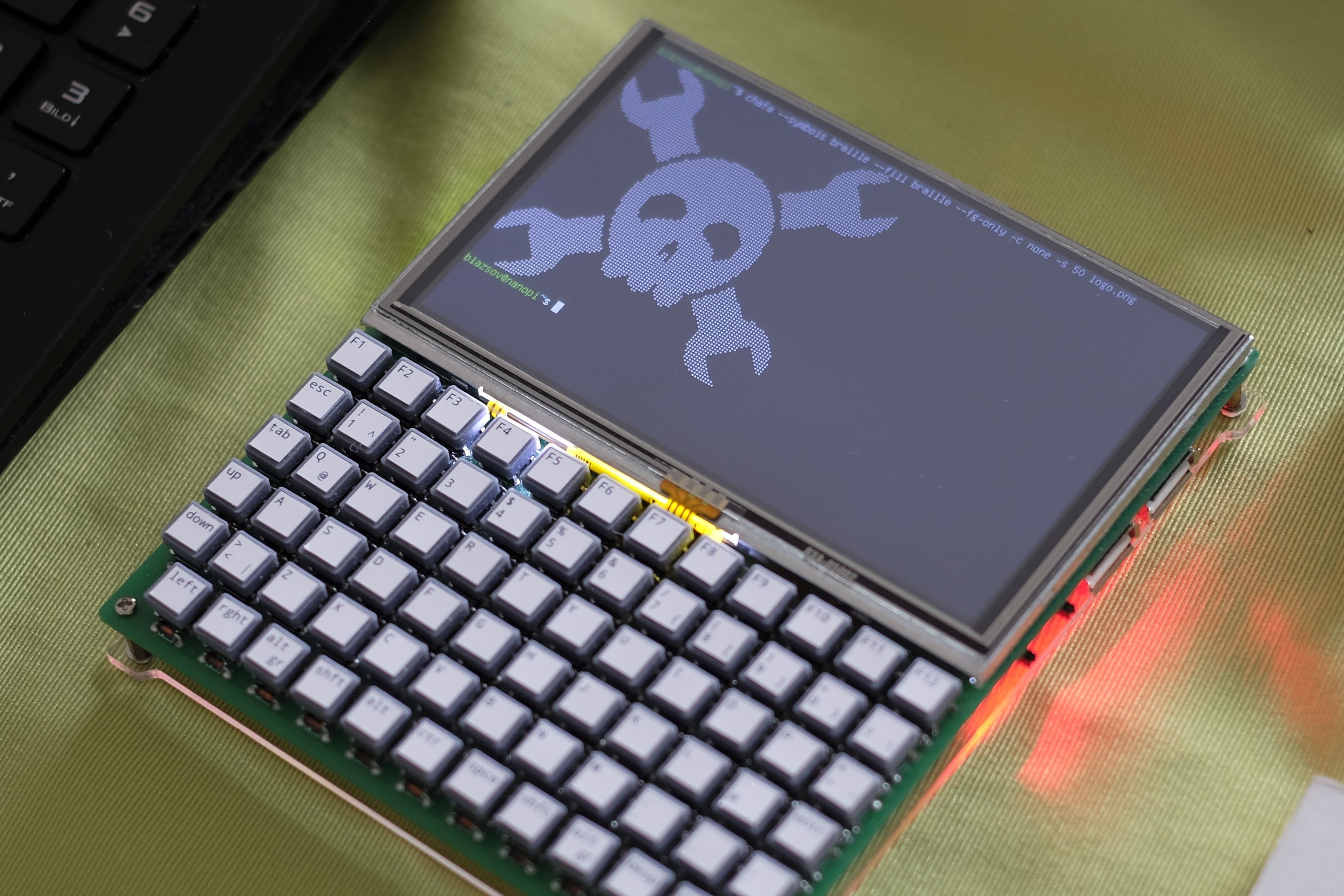
- 800x480 TFT display, 100 columns and 30 rows
- WiFi connectivity
- 71 key keyboard (caps lock is toggled by pressing the two shift keys simultaneously)
- Usable without any configuration
- 10000mAh LiPo Battery, 15 hours of battery life
- Charging over Micro-USB
- Built-in RTC
- ASCII and limited Unicode support, 256 colors
- 2 USB 2.0 ports
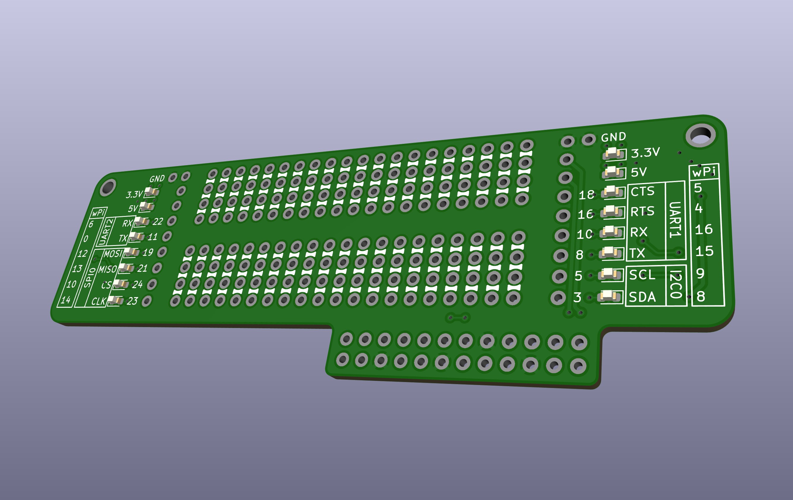
- 16 GPIO of the NanoPi Neo Air as well as SWD and UART of the Pi Pico are accessible
- Functioning workaround to display images
// Known issues
- The Micro-USB on the Pico is not accessible. This is intentional, because back-powering is not addressed. The Pico could be soldered using header pins to keep the USB accessible. In this case, the power switch of the Pico must be turned off, if it is directly connected to a USB power source.
- Connecting or disconnecting a charger interrupts the power output of the battery charging board.
- The footprint of the NanoPi Neo Air on the PCB is slightly incorrect, but not as much that it couldn't be mounted.
- The USB-ports are too close to each other, there isn't enough space to use them simultaneously.
- While the terminal is perfectly usable, it is not particularly fast.
// Video - sorry for the bad lighting, I improvised it from a headlamp and a piece of paper
// The story - feel free to skip if not interested :)
I have started learning electronics and Python with a Raspberry Pi 4 as a hobby last year and daydreamed a lot about turning the Pi 4 into a handled computer. I just couldn't figure it out how to get it compact enough to make it actually comfortable to hold. After some online window-shopping I stumbled upon the NanoPi Neo Air and impulse-bought it without knowing what to do with it. It doesn't have HDMI or DSI connectivity. After consulting the FriendlyArm Wiki I purchased a USB serial adapter as well. The setup using UART was surprisingly easy. At this point I thought I could just wire it together with a Pico and a screen and build an actual compact cyberdeck.
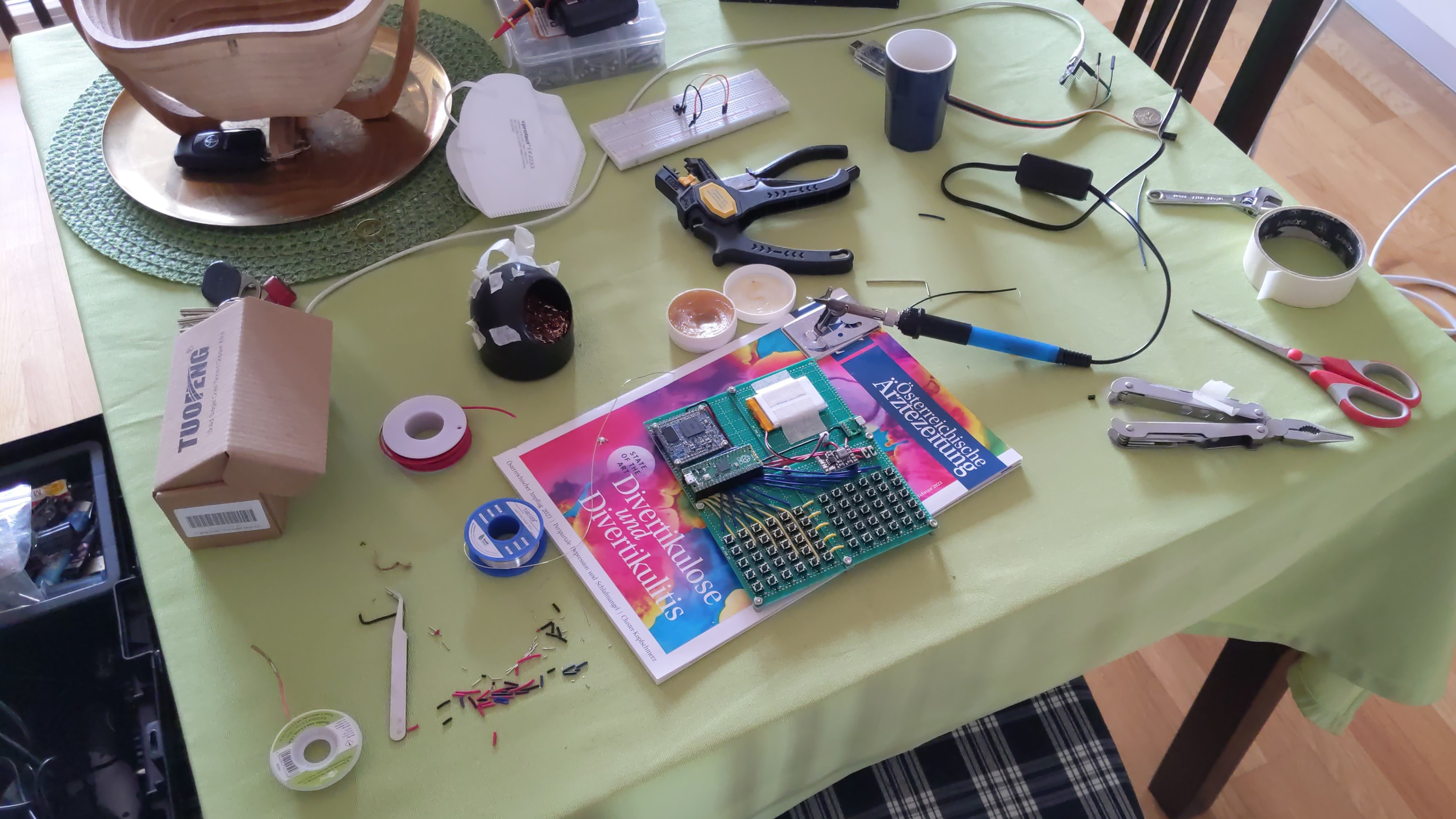
This happened in march 2023 and it took me 5 months to actually finish this project. The most time consuming part was the programming, as I had to learn everything from the beginning. I started off with one of those small 320x240 SPI TFT screens and programming in Python. It was slow, small, no scrolling or line-wrapping, but I got so far, that I could actually log in. Later I found the Adafruit RA8875 board, which communicates over SPI, can be used up to a resolution of 800x480, has a built-in ASCII font, cursor, line wrapping and scrolling. It can even draw characters a lot faster than UART sends them. Jackpot!
I started learning C as well as reviewing ANSI escape sequences and the TERM environment variable. At one point I decided to abandon the whole thing, as I couldn’t figure out how to implement the resizing of the scrolling area (for those who speak ANSI: \x1B[#;#r). On the next day during my commute it occurred to me, that I have read something in the RA8875 documentation about copying parts of the screen to other parts of the screen. It's called block transfer engine, and it saved the project. After arriving home I started looking up registers and it actually worked, alas a little too slow. I had to start looking into buffering and threading. Both proved to be surprisingly approachable with the Pico C SDK.
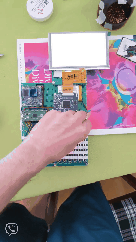
It was time to turn it from a conglomerate of protoboards into an actual custom PCB, so I started learning KiCad. I dropped in an RTC, because...
Read more »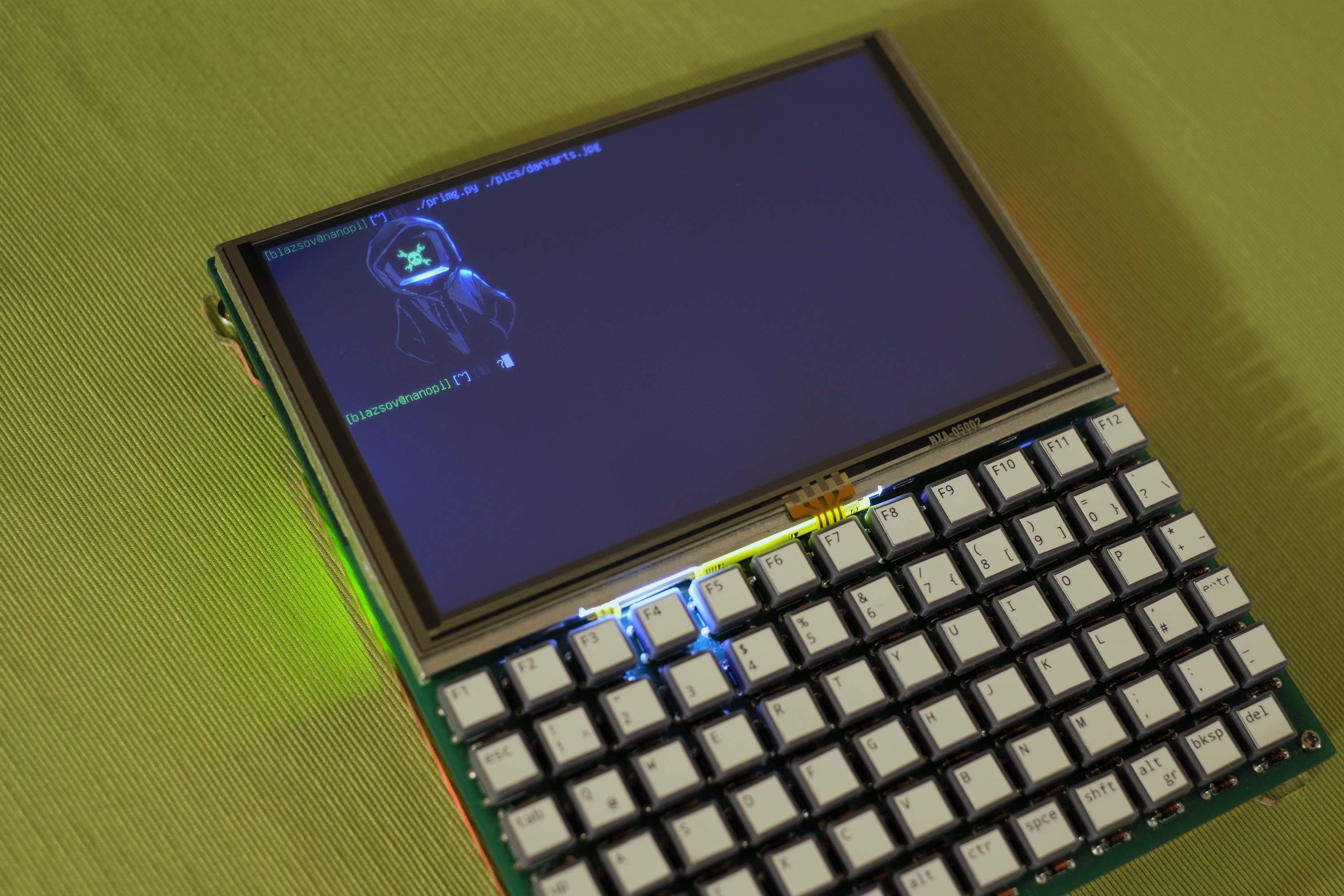


 ajlitt
 mitchell.dokken
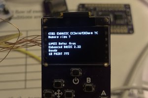
 chmod775
 kmatch98
meybe add Rotary Knob https://digiva.net/best-keyboards-with-rotary-knob/
small but very usefull when keyboard is not big.