electronicsworkshops
Overview
This article I2C OLED Display with Arduino demonstrates how to use the Arduino and the SSD1306 0.96-inch I2C OLED display. We’ll show you some features of the OLED display, how to connect it to the Arduino board, and how to write text, draw shapes and display bitmap images.
FOR FULL PROJECT :
https://electronicsworkshops.com/2023/07/30/guide-for-i2c-oled-display-with-arduino/
Introduction
In the realm of DIY electronics, one of the most fascinating combinations is the Arduino microcontroller and OLED displays. In this beginner’s guide, we will delve into the world of I2C OLED displays and explore how to integrate them with an Arduino. By the end of this article, you will have the knowledge and confidence to embark on exciting projects of your own.
What is an OLED Display?
An OLED (Organic Light-Emitting Diode) display is a cutting-edge technology that emits light when an electric current is applied. Unlike traditional LCDs, OLEDs do not require a backlight, resulting in vibrant colors, high contrast, and excellent visibility, even in low-light conditions. These displays are widely used in smartphones, smartwatches, and numerous other electronic devices.

What is I2C Communication?
Inter-Integrated Circuit (I2C) is a simple and widely-used serial communication protocol that enables multiple devices to communicate over just two wires: SDA (Serial Data) and SCL (Serial Clock). I2C is particularly useful for connecting peripherals, like OLED displays, to microcontrollers such as Arduino, allowing seamless data exchange between devices.
Working Principle Of I2C OLED Display with Arduino
The I2C OLED display with Arduino works by establishing communication between the Arduino and the display using the I2C protocol. The Arduino sends commands and data to the display, which processes and controls the individual pixels on the OLED screen to display the desired content. The Arduino can continuously update the display, making it suitable for various applications, from basic text displays to more interactive and dynamic projects.
Bill Of Materials
| SN | COMPONENTS NAME | DESCRIPTION | QUANTITY | |
|---|---|---|---|---|
| 1 | Arduino Board | Arduino nano | 1 | https://amzn.to/3Qe71y5 |
| 2 | Connecting wires | jumper wire | some | https://amzn.to/3fMoSw7 |
| 3 | Breadboard | Normal | 1 | https://amzn.to/3FUQlXe |
| 4 | OLED Display | SSD1306 0.96-inch | 1 | https://amzn.to/3q6XX3p |
Circuit Diagram

- Connect the GND pin of the OLED display to any GND pin on the Arduino board.
- Connect the VCC pin of the OLED display to the 5V pin on the Arduino board.
- Connect the SDA pin of the OLED display to the A4 (Analog 4) pin on the Arduino board.
- Connect the SCL pin of the OLED display to the A5 (Analog 5) pin on the Arduino board
Libraries
To control the OLED display you need the adafruit_SSD1306.h and the adafruit_GFX.h libraries. Follow the next instructions to install those libraries.
1. Open your Arduino IDE and go to Sketch > Include Library > Manage Libraries. The Library Manager should open.
2. Type “SSD1306” in the search box and install the SSD1306 library from Adafruit.

3. After installing the SSD1306 library from Adafruit, type “GFX” in the search box and install the library

Testing the OLED Display
After wiring the OLED display to the Arduino and installing all required libraries, you can use one example from the library to see if everything is working properly.
In your Arduino IDE, go to File > Examples > Adafruit SSD1306 and select the example for the display you’re using.

You should get a series of different animations in the OLED as shown in the following

Schematic Diagram

PCB Diagram

3D Diagram

Manufacturing Files
Bill of materials
Position Files
Order Directly from PCB WAY
I have already uploaded all these required manufacturing...
Read more »
 Alexander
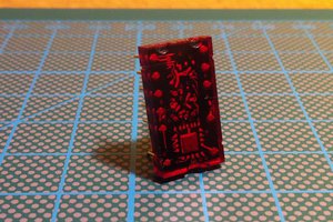
 antiElectron