 Chris
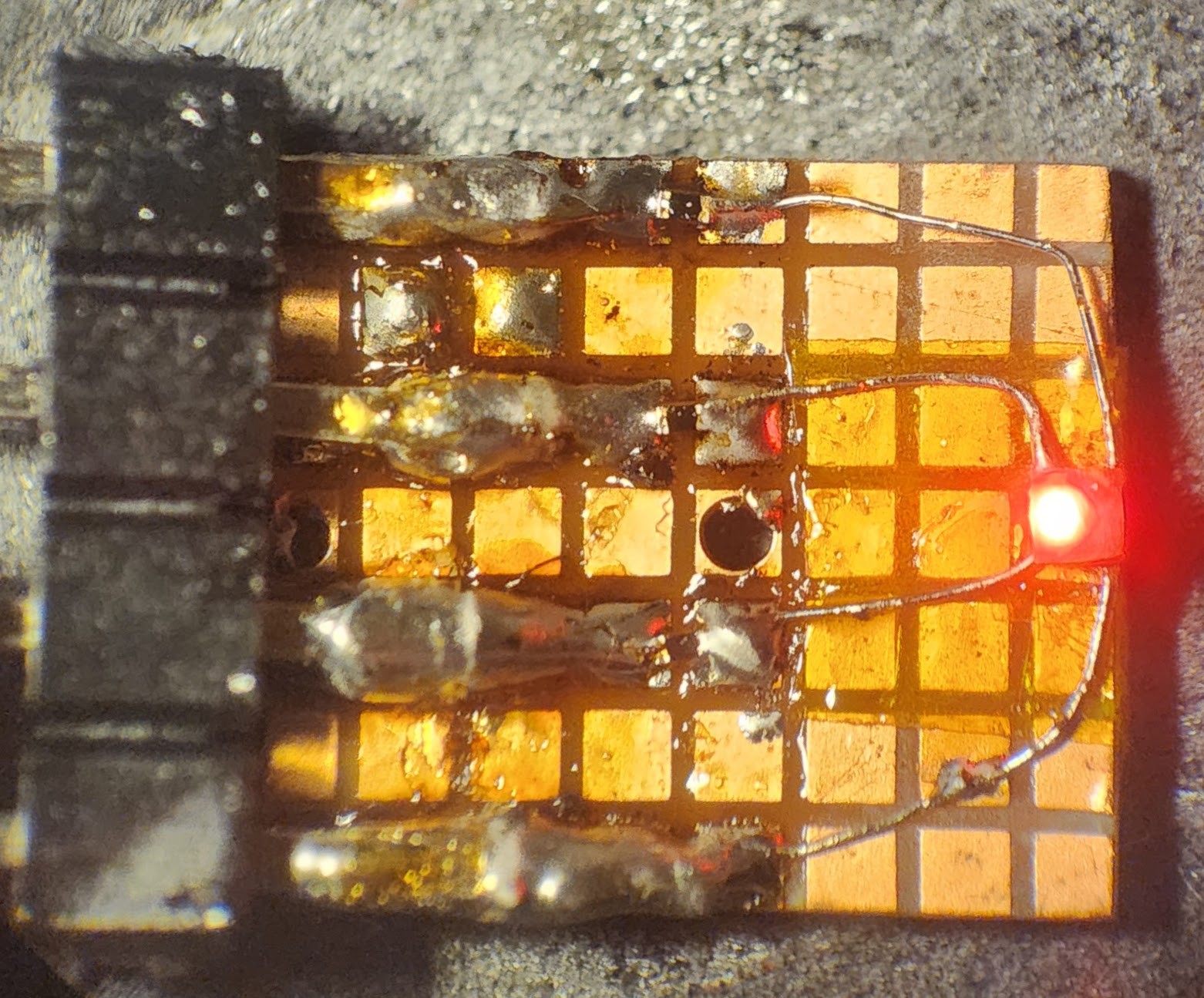
ChrisA short log with lots of eye candy, but perhaps one of the most triumphant logs yet! In short, I have had trouble with my charging IC for the past few months. First, it wouldn't charge all the way, and the light would remain forever red. Second, it would stay green (reporting fully charged) even with no battery connected. This is undesired behavior which was not present on Rev. 2 of the boards, which only suffered from the former issue.
I realized that if I want the DONE and CHRG light to both remain off while there is no battery connected, I need to remove the suggested capacitor at battery input.
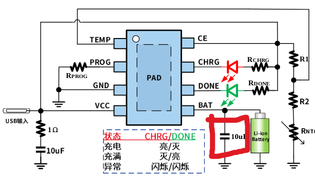
I guess it makes sense that the chip behaves this way. From what I can tell, the IC is essentially charging the capacitor to a little over 4V and then reporting DONE. Based on some probably erroneous calculations, the capacitor is being charged at about 3 uA and has a DC impedance of about 1.32 MOhms.
This chip does have a low current "trickle charge" meant to revive dead cells. It's possible that 3 uA is enough for the chip to operate in that regime and enable it's constant current supply into the capacitor.
Either way, I get my desired behavior when I remove the input capacitor. This seems like a bad idea, because it is. Without this capacitor, the CHRG and DONE light flip out when I press my finger to the contacts while the battery is disconnected and who knows what sort of instabilities that could lead to. I wonder if I can just use a TVS diode to kill any transients. I found a 0201 TVS diode with a leakage current of just 0.2 uA. Maybe that will be low enough as to not trigger the charging IC while still providing some transient protection.
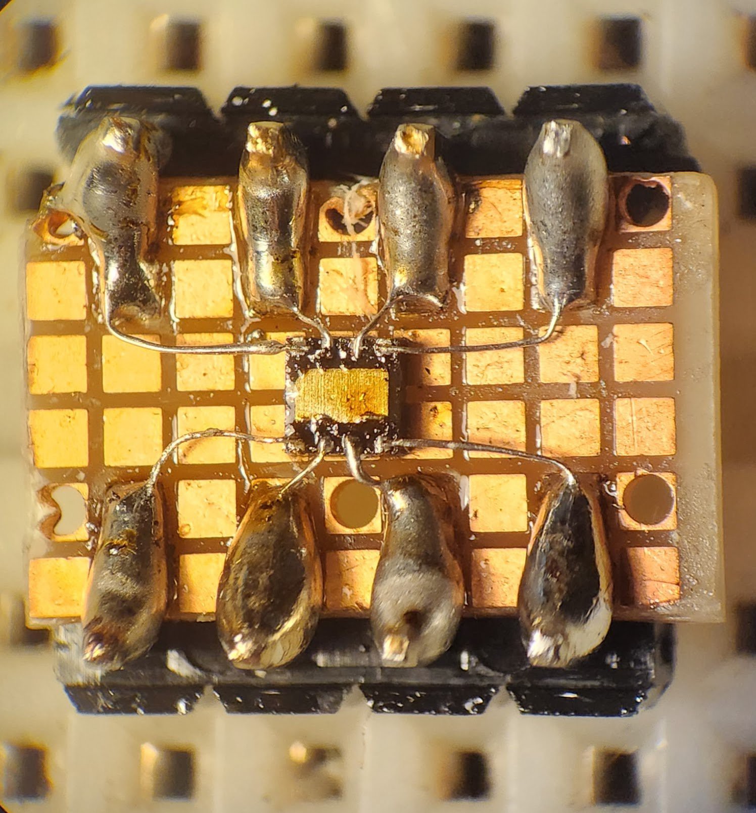
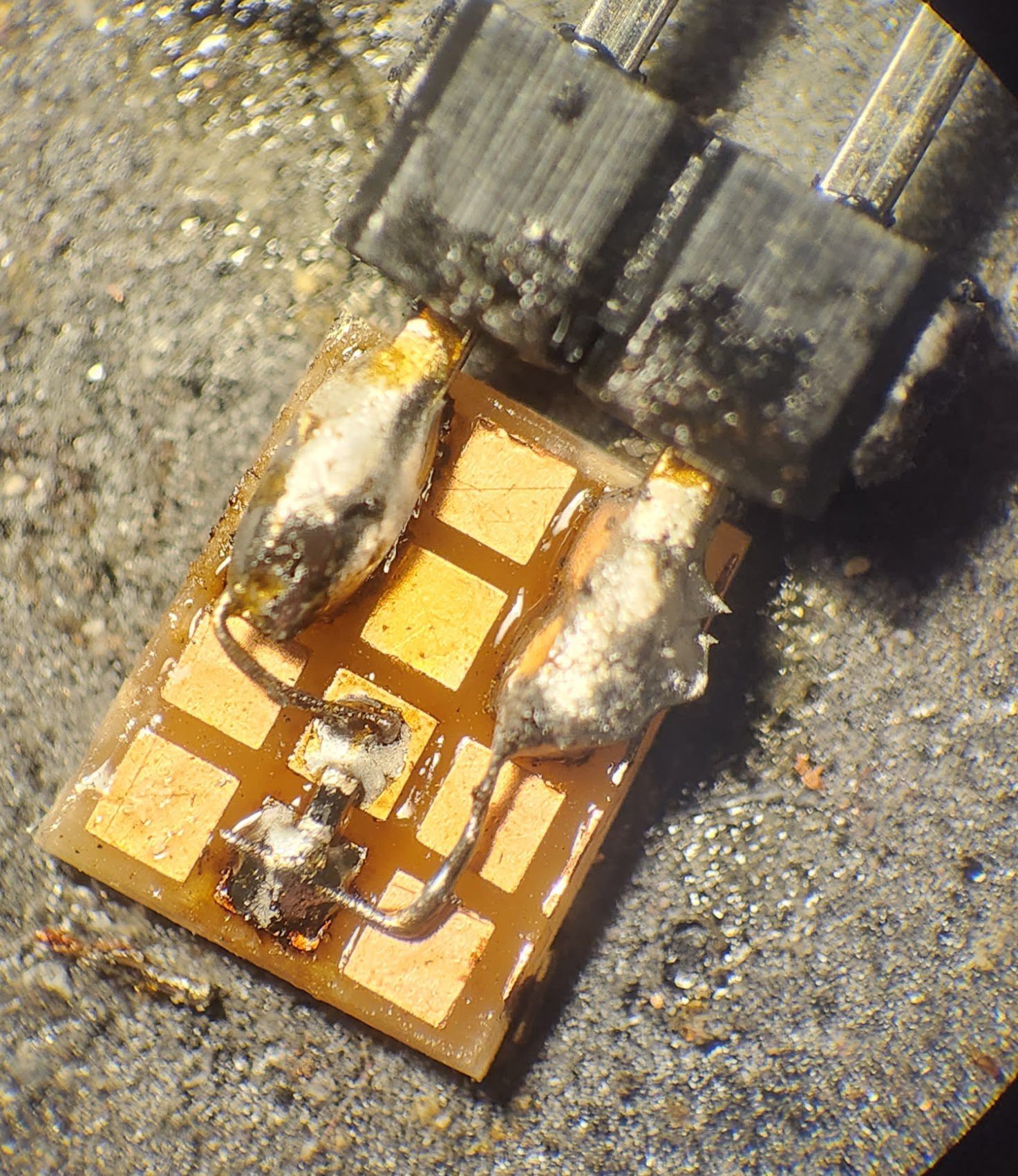
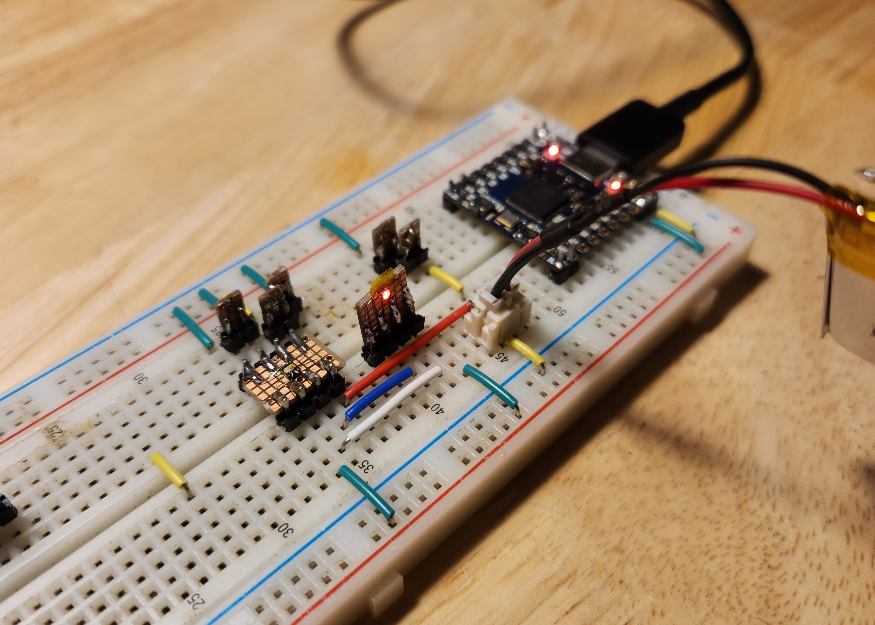
How did I figure all of this stuff out? I breadboarded! How do you breadboard components that could fit through the eye of a needle? Just check out the pictures below...
Discussions
Become a Hackaday.io Member
Create an account to leave a comment. Already have an account? Log In.