Update - Nov 2023
See video below and project log for more details
Motivation
A few weeks ago, I found an Intel SDK-85 Single Board Computer at a ham-fest. I am a sucker for anything with a keypad and 7 segment displays. Having had a Heathkit ET-1 disappear in front of me, I made sure to act on this one as quickly as possible. I didn't even know what it was, but I knew I needed it.
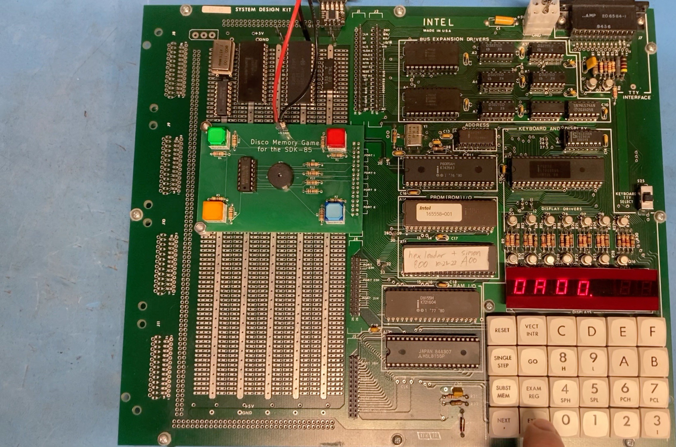
It's an Intel 8085 hardware/software development kit from the late 1970s. It's aimed at the hobbyist/education market. It sports a fine manual, generous 36 GPIO ports and a meager 256 BYTES of RAM. It can be upgraded to 72 ports, 512 bytes of RAM, 2K EPROM, plus a full bus
expansion.
Being such a simple and vintage board, I wanted to recreate the experience of building something in a 1970s basement. I looked for a problem space that was well matched to the SDK-85 and its obvious emphasis on hardware integration. The answer became obvious - recreate the legendary Simon electronic game from 1978.
This is where alternative history took over. I imagine myself as a lowly hobbyist inventor in my basement. I could afford an SDK-85, but no teletype, and certainly not a "real" computer. I would do this with the books, graph paper, pencils, and my trusty HP calculator.
Research and Design
I started by studying the Simon itself. I didn't have one so I watched every YouTube video I could find. I noted the color pattern and matched the tones to notes on my piano - E, A, C#, and E. The
buzzer is the lowest D. I also noted the game play patterns, such as displaying the correct color and tone for a correct guess, but also showing the correct color and the buzz for an incorrect guess, which also ends the game.
I made some concessions and have a simplified version of the game. I omitted the GAME and DIFFICULTY switches, and also the START button. Instead the game is started by simply pressing any of the 4 colors. I also don't stop the game after 10 moves, but allow the player to keep going for up to 256 moves. I don't believe these choices detract from the game play and arguably make it more intuitive.
Lastly, when reading player input, the light and tone are displayed for a half second rather than however long the player held the button down. This allowed a single tone routine and table to be used. It also eliminated the need for any complex debounce routine as the player is given sufficient time to release the button while the tone is playing.
Next came hardware decisions. The SDK-85 has a large wire-wrap prototyping area that makes up the left half of the board. The buttons, lights, and speaker could all be installed here. However, I was hesitant to "hack up" a vintage piece of hardware with non-reversible modifications. I was also worried about pressure from the buttons flexing the board.
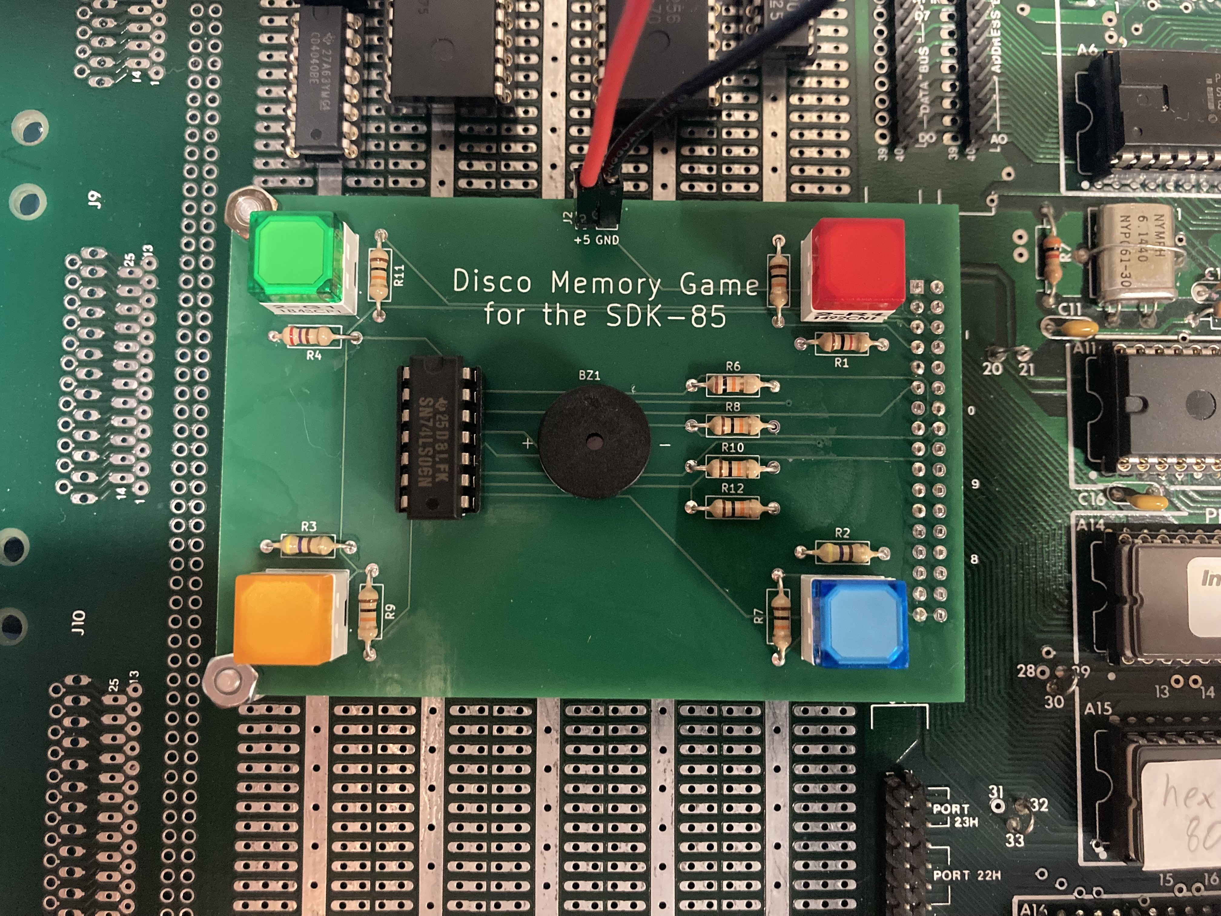
So, I decided on a detached daughter board that would house the 4 push button switches, lights, and speaker. The daughter board connects to the SDK-85 using a ribbon cable into an IDC header I installed on the port 0/1 connector. The switches I had on-hand were panel-mount type, so I drilled through the board to mount them - another reason to keep these on a daughter board.
The original Simon used incandescent lamps and a traditional cone speaker. I decided to use colored LEDs and a piezo buzzer. These parts are more readily available, are more compact, and use less power. I am straying away from period correctness here, as blue LEDs weren't invented until the 90s. However, this has no impact on the gameplay nor on the software development methodology, which is my real focus here.
Building It
The board was wire wrapped on a hot Saturday afternoon and does not represent my best work. I completed the board in its entirety before getting to work on the software. ...
Read more » jimshortz

 Peter Noyes

 doctek