 Guyrandy Jean-Gilles
So far the hardware of this project has followed the Raspberry Pi Hat form factor. The last PCB was about as slim as I could get it following that spec and using tactile switches as inputs.


As I said in the last project log, I'm not set on sticking to the Raspberry Pi platform, but Pi form factors are standard, so the easiest way to slim down the hardware with minimal software changes is to produce a carrier board for the compute module 4.
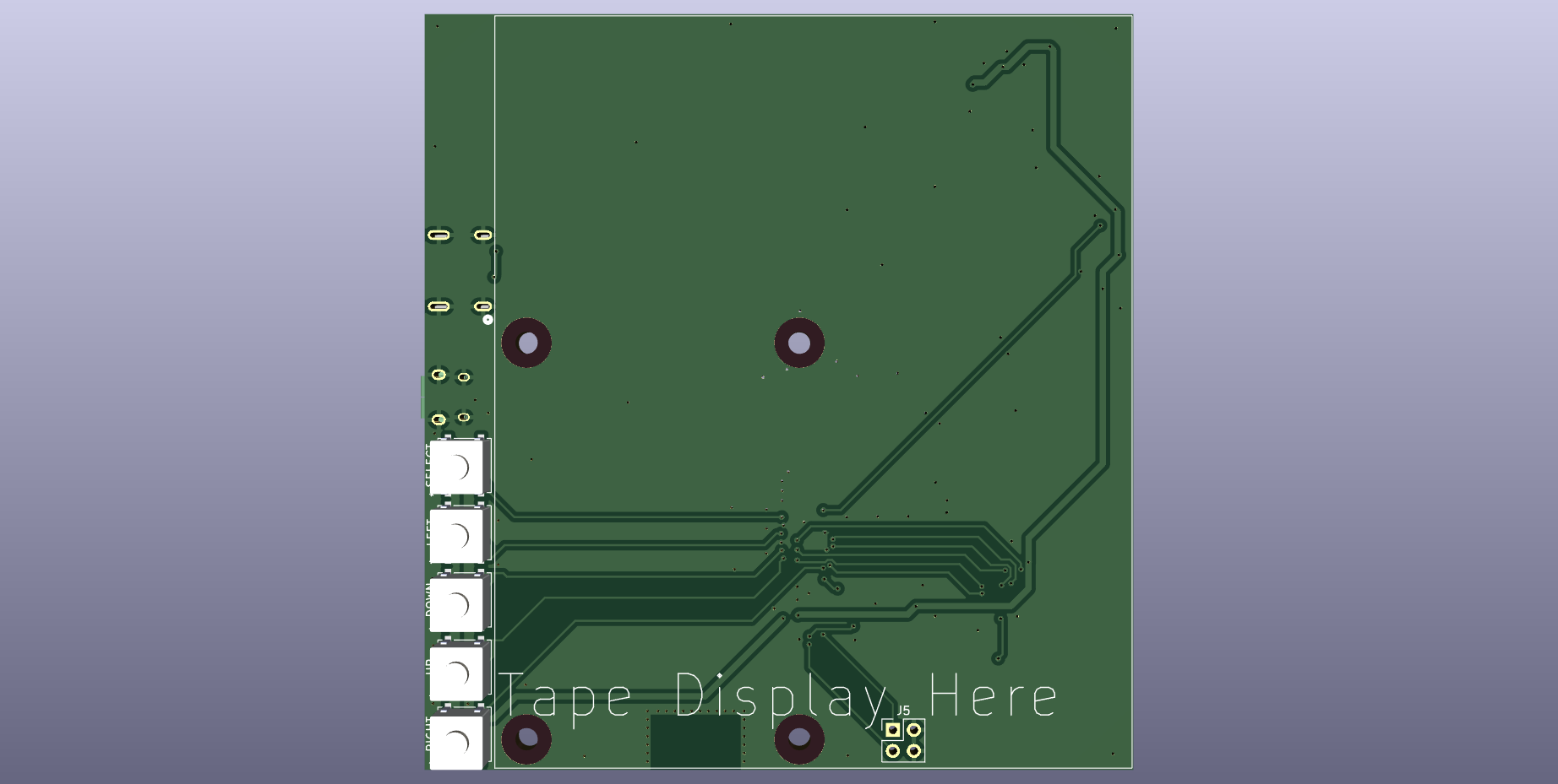
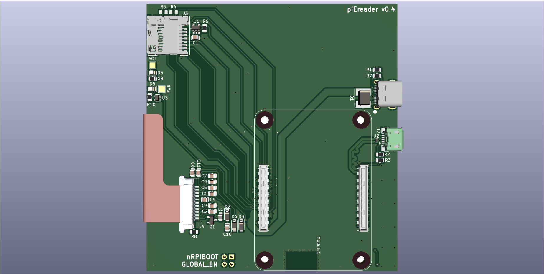
This layout wasn't as simple as replacing the 2x20 headers connectors with 100 pin Hirose connectors. The carrier board needed to handle power input, SD cards, and USB traces. You'll notice a USB C and USB micro connector. The former is for 5V power and the latter is for USB client connections. I could've routed both in a single USB C connector but I don't want to be debugging USB right now. The layout is stolen from Shawn Hymel and it worked for him so why try something new.
I have compute modules with eMMC but they are still hard to source and I want to be able to use SD cards if need be. Routing the SD card traces and the 24-pin ribbon cable connector resulted in a sea of vias. That plus the USB data traces should have lead me to a 4 layer board, but I'm a frugal engineer and routed everything on two layers. Hopefully it all works.
Notice the lack of battery hardware. If this was a final production layout I would've taken the time to implement portable power, but that will come in a later board revision.
For the latest software and hardware files, please visit the development branch of the project's repository.
Discussions
Become a Hackaday.io Member
Create an account to leave a comment. Already have an account? Log In.