 Guyrandy Jean-Gilles
I'll skip to the happy ending. I can drive the display, the back light, and can read data from the touch screen, but achieving those milestones took much much longer than it should've. This update won't have much info on the actual e-reader project but is more a rant reflection on mistakes made while bringing up GDEY042T81-FT02 so I, and hopefully you, don't repeat them. Buckle up.
The Development Board
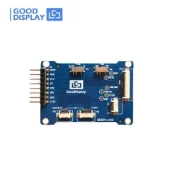
The DESPI-C03 development board has three sets of connectors. One for the e-paper display. One for the back light. Two for the touchscreens as they have different pinouts depending on the size you have. You would reasonably assume that connecting all three ribbon cables of GDEY042T81-FT02 to a single DESPI-C03 board would drive all the screen's components. That's what I did, but what I did was, in fact, wrong.
Everything worked as expected when I attached only the 24-pin e-paper ribbon cable to the development board. However, when I attached the 6-pin touch screen cable, the e-paper refused to update.
Mind you, I was not running any new code. The exact same firmware that drove the display perfectly didn't work properly when I connected the touchscreen ribbon cable. This led me to believe there was a hardware issue. So I examined the DESPI-C03's schematic.
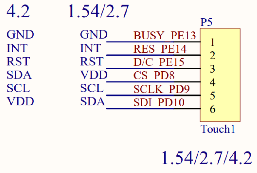
The labeling is extremely confusing but it looked like the same pins are used for SPI communication to the e-paper and I2C communication to the touchscreen. This would obviously cause problems. There's absolutely no warning of this on the DESPI-C03 silkscreen or on its product page. I only noticed because the demo video for the GDEY042T81-FT02 shows two separate development boards being used to drive the e-paper and read from the touchscreen.
Luckily, I bought two DESPI-C03 boards and had plenty of e-paper driver boards from earlier prototyping, but I wouldn't be surprised if other people weren't as lucky. But using two different DESPI-C03s did not resolve my issues.
The Touchscreen
If you're like me, you try to get vendor supplied code up and running before fiddling with any of you're own stuff. This way, when your custom written code evidently doesn't work, you can run the known, good vendor code as a sanity check. But the vendor code was the source of insanity.
Good Display provides several different example applications for Arduino, ESP32 (which was just Arduino-ESP32), STM32, etc. I had an ESP32 lying around so that's what I used to run the vendor code. Below is the content of that code's README in it's entirety.
SDA¡¢SCL---Have to be connected to a resistance to VCC

A0-INT
A3-RST
A4-SDA
A5-SCL
Sparse, but little documentation is better than no documentation. To translate, pin A0 of the ESP32 should connect to the INT pin of the FT6336 (the IC that drives the touch screen), pin A3 of the ESP32 should connect to the RST pin of the FT6336, etc. I wired up my ESP32, DESPI-C03, and GDEY042T81-FT02 and... nothing. I quintuple checked the cryptic DESPI-C03 schematic but couldn't figure out what I was doing wrong. Eventually, I thought Good Display's code a lost cause and explored other FT6336 libraries for the ESP32. There are a couple to pick from, but I had the same problem. I couldn't read anything from the touchscreen no matter what.
I connected my ESP32 to a known good piece of I2C hardware just to make sure I wasn't going crazy and confirmed that my ESP32 hardware functioned. So why did the touchscreen not work? If you're guessing I had a wiring problem, you're absolutely right. I only realized this when I looked at the silkscreen on the ribbon cable.
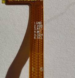
Pin 2 is supposed to be VDD not, INT. Pin 4 is supposed to be INTnot SDA. Pin 5 is supposed to be SDA not SCL. Pin 6 is supposed to be SCL not VDD. You can see how following the vendor's code documentation would result in problems. Worse, the silkscreen from DESPI-C03 does not warn of this potential miss-wiring at all. The correct wiring has FT6336's GND connected to the DESPI-C03 pin labeled BUSY. VDD connects to RES. RST to D/C. INT to CS. SDA to SCLK. SCL to SDA. The DESPI-C03 silkscreen is useless with respect to wiring the touchscreen.
I wasn't completely hopeless in discovering the wiring issue. The product page for the standalone touchscreen has the correct pinout. Is the touchscreen product page linked to the GDEY042T81-FT02 page? No. On the the DESPI-C03 page? No. I assume most people who bought the display and adapter without contacting an application engineer had to bumble in the dark like I did. But my failures did not end there.
I2C with BCM2835 Library
For some reason, the firmware that read data from the touchscreen would freeze. The whole Raspberry Pi wouldn't freeze; just the code. Killing and restarting the code would fix the problem until the next lock up. Sometimes it took ten seconds. Sometimes it took three minutes. But regardless, an e-reader wouldn't be very useful it freezes randomly whenever you touched the screen.
I shamelessly used trial and error to figure out an order function calls that would prevent a lock up. Here's a minimal example.
#include <bcm2835.h>

#define INT_PIN 6

uin8_t ft6336ReadByte(uint8_t address);

uint8_t main(void)
{
    while(1)
    {
        if (bcm2835_gpio_lev(INT_PIN) == 0)
        {
            /* FT6336 has an interrupt pin (INT_PIN) that pulls low
            * when there is touch data availabe
            */
            uin8_t touchData = ft6336ReadByte(0x4); // A data register of FT6336        }    }
}

uin8_t ft6336ReadByte(uint8_t address)
{
    uint8_t data = 0;
    bcm2835_i2c_begin();
    bcm2835_setSlaveAddress(0x38); // I2C address of FT6336
    bcm2835_i2c_set_baudrate(1000000);
    delayMs(10);
    bcm2835_i2c_write(&address, sizeof(address));
    bcm2835_i2c_read(&address, sizeof(data));
    bcm2835_end();
    return data;
}
Polling the FT6336 IC without checking its interrupt pin would eventually cause a lock up. Not delaying before writing and reading the IC would cause a lock up. Setting the target I2C address outside the super loop would cause a lock up. Same thing for the baudrate. For some reason, the above order of function calls would not cause a lockup. I left the code running for days and continuously touched the screen for 5+ minutes over a series of days, without stopping the loop, to make sure I could continuously read without a lockup. It's passed all my tests but I couldn't tell you why.
Note, I didn't see this problem with the ESP32. I only saw the code hanging when using the Raspberry Pi and the BCM2835 library. Also important to note that normal taps and swipes didn't cause any problems. I saw issues when I held and dragged my finger across the screen for extended periods of time. But because I couldn't consistently reproduce the freeze over the same time span with the faulty code, it made me worry the lock up might happen during normal e-reader operations.
I found two threads about this in the BCM2835 list serv. One dating back to 2015, the other as recent as June of 2023. The BCM2835 revision history shows a timeout check added to the I2C code for the most recent version (1.73),
So I upgraded the library to version 1.73 and I got even more errors. The new error BCM2835_I2C_REASON_ERROR_TIMEOUT is returned for nearly every call ofbcm2835_i2c_write. Here's the thing, even when this error was returned, sometimes the data from FT6336 was correct. The data returned was only faulty when BCM2835_I2C_REASON_ERROR_DATAwas returned. Remember, there were no errors with version 1.71 of the library and the touch data is always correct. I could just require the use of 1.71, but I wanted to discover the root cause of the problem.
It was in line 1318 of bcm2835.c
unsigned long Failsafe = len * 1000;
len is the length of data being read from the I2C sensor. Failsafe counts down during the loop where the bcm2835 library waits for a hardware response. If Failsafe reaches zero, the loop is broken without verifying a response from the peripheral. This behavior is specific to version 1.73 of the bcm2835 library. 1.71 doesn't have this Failsafe variable. I suspect that, in most cases, the Pi is timing out mid transmission but the sensor finishes sending data during the cleanup processes after the timeout. Because version 1.71 doesn't have any timeouts, these mid transmission breaks didn't occur.
Either way, if you want to use FT6336 with the bcm2835 library, stick to version 1.71.
Back-light
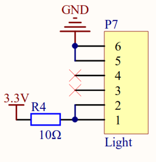
We return to the poorly designed DESPI-C03 for back-light woes. From the schematic, you'd think you'd only need to apply 3.3V for the back-light to turn on.
Wrong. This was actually the first thing I tried when I got the hardware, but it was the least important component to bring up, so I skipped it to work on the e-paper and touchscreen. After bumbling through the documentation for the latter, I decided to find the stand alone back-light product page.
- I discovered that the back light is actually 7 LEDs connected in series.
- The operating voltage of the front light is rated <= 21V.
- Good Display actually sells a dedicated front light driver that can output 9V, 12V, and 21V.
Is any of the above information on the GDEY042T81-FT02 page? Well actually, the front light voltage is mentioned as <=21V. But again, the DESPI-C03 schematic made me think 3.3V was fine. All the other information was no where to be found on the GDEY042T81-FT02 documentation.
When I connected 21V directly to the back-light ribbon cable, bang! Let there be light!
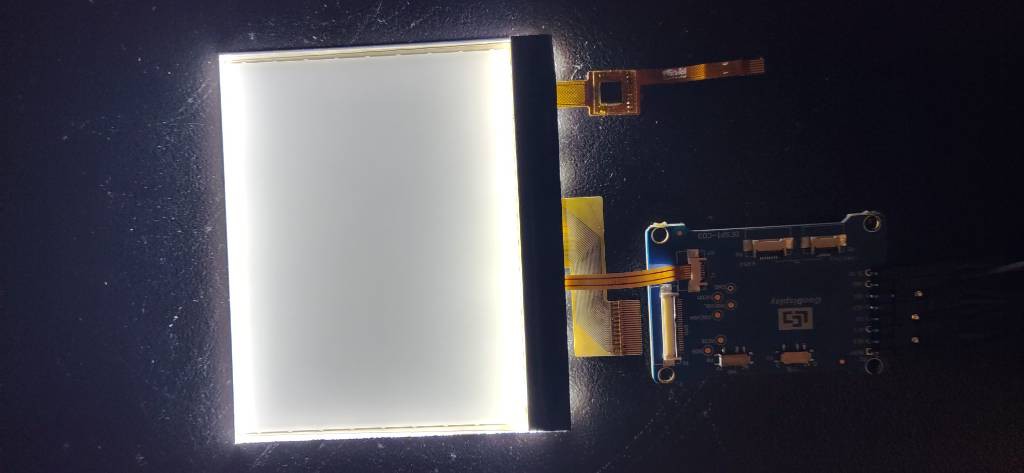
Finally, all the components of the GDEY042T81-FT02 were verified functional.
</rant>
I hope you read this before trying to bring up GDEY042T81-FT02 yourself. If you're here after hitting a brick wall, I hope you haven't spent much time troubleshooting. If you're reading this after almost giving up on the hardware, join the club. We play DnD Thursday nights. Any way, the code is in the Gitlab repo. Use it as a known good reference because I certainly didn't have one.
If I would leave you with any lessons, it's that all documentation is wrong until proven otherwise.
Discussions
Become a Hackaday.io Member
Create an account to leave a comment. Already have an account? Log In.