 Dan Julio
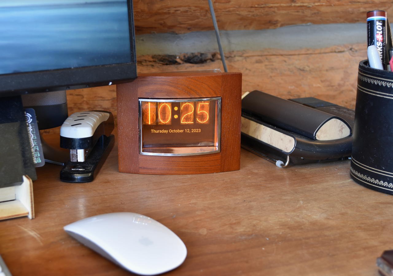
I live in some foothills and cell service is terrible. So I have an Ooma VOIP box as a landline and an old GE DECT wireless phone on my desk. Unfortunately most of the calls I get are spam so I decided to use a circuit I had built for weeBell testing and the great spandsp library to make a Caller ID box so I can see who is calling before picking up. Doing nothing but displaying the rare Caller ID Information seemed boring so why not make a clock too. And if one is going to make a clock, well it should be a nixie clock. Or at least a faux nixie clock and I'd get to use up an old Adafruit 3.5" 480x320 pixel touchscreen where the touchscreen part no longer worked. I even had an old picture frame to give it a faux classy look that fits in with my log house! For this project I was able to source everything from stuff I already had.
In North America, the Caller ID process works by encoding the phone number, timestamp and optionally other information like caller name with a 1200 baud FSK Bell 202 modem and transmitting that on the line after the first ring. At minimum a Caller ID box has a FSK decoder fed by an analog input. In my case I also used a pulse generated by each ring waveform to help identify a good time to start the decoding process.
The test circuit I originally built for weeBell was designed to let me safely look at the audio and ring information to debug its Caller ID generation capability. I started with the circuit diagram I found with this Arduino project and ended up modifying it slightly based on the parts I had on-hand and the desire to add a little more filtering. The schematic for my test circuit is shown below.
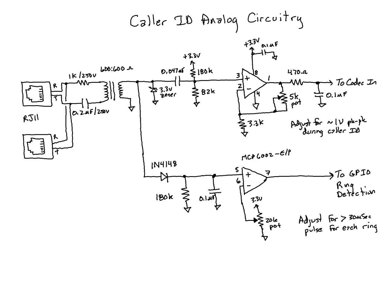
A typical waveform looks something like this.
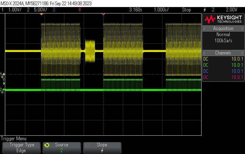
The audio output is on channel 1 and the ring output is on channel 2. The actual caller ID transmission can be seen after the first ring (the analog signals associated with the ring pulse are just low frequency noise that made it through my filters).
Initial failures
The spandsp library is based around 8 kHz audio sampling so I figured I could use the 12-bit ESP32 ADC being read by the I2S peripheral to generate the audio stream. Unfortunately days of effort amounted to a very unreliable detector. I never could figure out why. I dumped the data I read, it looked OK. I tried a bunch ways to properly scale the data and remove DC offsets. Decoding would usually work the first time and then rarely after. Finally I gave up on this approach. I think for all its promise the ESP32 ADC + I2S is just problematic.
Using a real codec
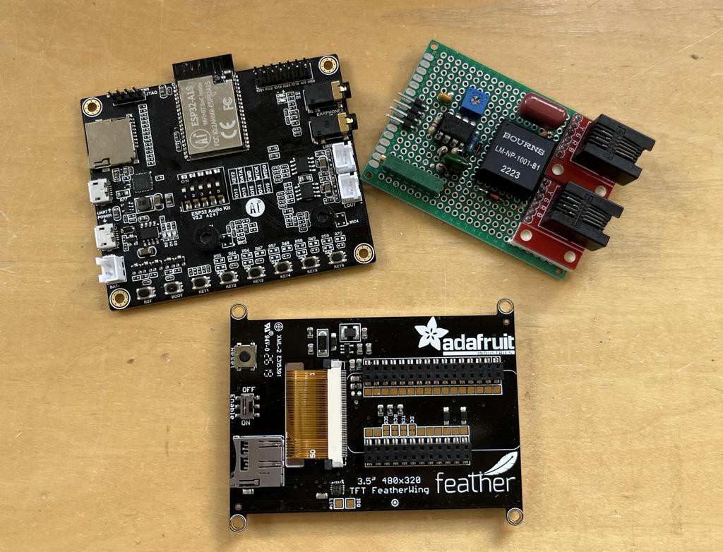
Fortunately I had the AI thinker board I had originally bought when I first started playing with Bluetooth Handsfree telephony at the beginning of the weeBell project. I ported over the ES8388 audio driver to my test code and was rewarded by reliable decoding almost right away.
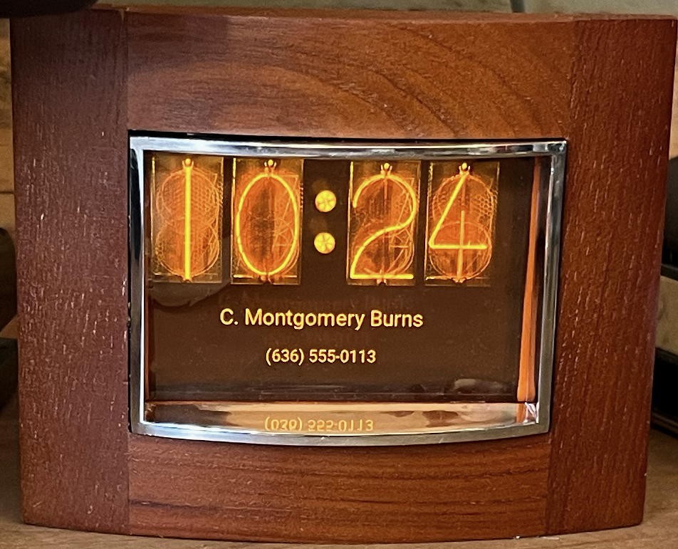
Now I could start on the real gadget and some quick google searching led to some great nixie tube photographs. I carefully cropped each digit and then used those as the basis for a set of bitmaps (the zero digit has a second copy with the intensity turned way down to use when leading-zero blanking for the hours display). A picture of the Russian INS1 neon indicator made a great colon (the second colon is just the original image rotated a bit). Actually 4 pictures of the colon were developed (two for it ON and two for it OFF so it can blink every second). Once again I used LVGL as my goto graphics library to provide the GUI. The LVGL website has a utility that let me take all the images and convert them to bitmaps to display on a canvas widget. The Espressif IDF has support for NTP time setting so it was easy to make a clock that would get its time using Wifi and then constantly update itself.
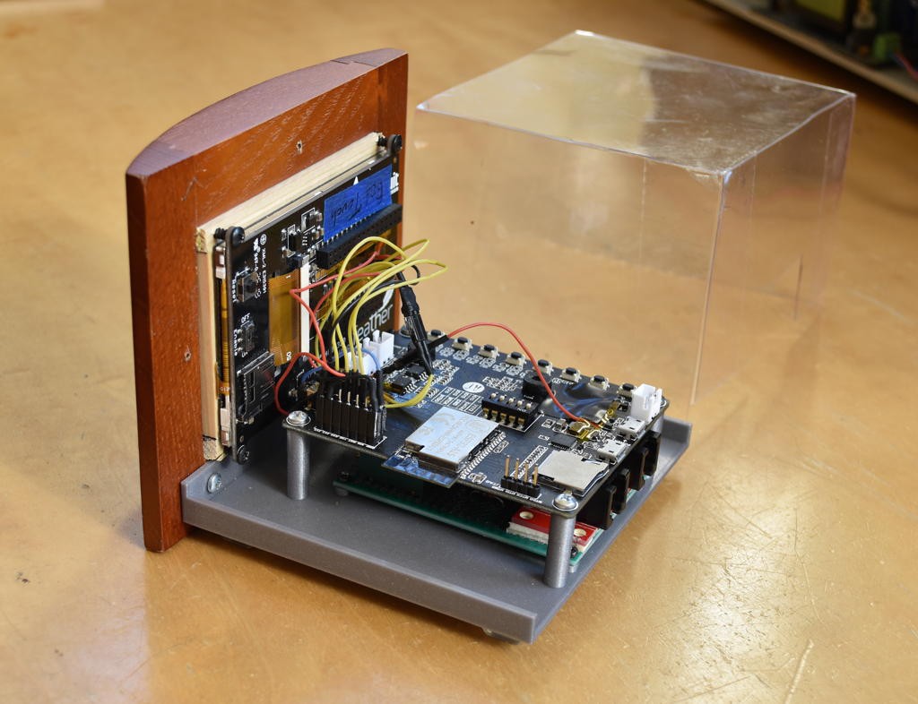
The final gadget resides behind the picture frame sitting on a simple 3D printed base. Although the nixie and colon images are already orange, a piece of an orange acetate lighting filter was cut and placed behind the glass to act as a filter. It works really well and the display looks even better than in these pictures. I was needing to move on from this project at this point so a sturdy mylar sheet was formed and taped to act as a dust shield. It's simply taped to the base using transparent shipping tape.
Normally the clock displays the date below the time. The Caller ID information replaces that temporarily (for a minute).
Making your own
I attached a zip file containing the IDF v4.4.4 project to this hackaday.io project (nixie_caller_id.zip) in case you'd like to make your own or use the code as the basis for your own clock. It's designed to drive the 480x320 pixel HX8357-based LCD on the Adafruit board and needs a ES8388 codec chip (which is conveniently included in the ESP32 module on the AI thinker Audio Kit board).
There are two sets of connections. One for the analog board and one for the display board. Most can be made with the existing headers on the AI thinker board but I did solder a few wires to the board.
Analog connections:
- 3.3V / GND - AI thinker expansion header
- Ring Output - GPIO21 on the AI thinker expansion header
- Analog Output - soldered to both L+R Line In audio jack (rear two pins)
Display connections:
- 3.3V / GND - AI thinker expansion header
- 5V/USB (for backlight) - Soldered to the output of the diode on the USB Power connector on the AI thinker board
- LCD CSN - GPIO19 on the AI thinker expansion header
- LCD DC - GPIO23 on the AI thinker expansion header
- LCD SPI CLK - GPIO5 on the AI thinker expansion header
- LCD SPI MOSI - GPIO18 on the AI thinker expansion header
The ES8388 inside the module is connected as follows:
- BCLK - GPIO27
- WS - GPIO25
- Data In - GPIO26
- Data Out - GPIO35
- I2S SDA - GPIO33
- I2S SCL - GPIO32
The code is using the ES8388 Line 2 inputs (through a DC-blocking capacitor).
You'll need to put in your own Wifi credentials in the components/clock/wifi.h file. Also set your timezone in the main/main.c file.
In case you want to change the GPIO assignments look in the following files (sorry I was in full-on hack mode and didn't bother with the niceties of using the sdkconfig or even a common header file):
- main/audio_task.c - ES8388 I2S signals (in the _audioInitI2S subroutine)
- components/lvgl_tft/disp_spi.h - LCD CSN, SCLK and MOSI signals
- components/lvgl_tft/hx8357.h - LCD DC signal
- components/i2c/i2c.h - ES8388 I2C signals
- main/ring_task.h - Ring signal
If you just want a faux nixie clock you can disable starting "audio_task", "cid_task" and "ring_task" in main.c.
Adapting for other Caller ID systems
The spandsp library can also decode the V23 FSK and DTMF encoding schemes used around the world. Usually these precede the first ring (or may follow a special very short first ring). It would take a little hacking but this code can support these other protocols. Probably to support a protocol that sends the information before the first ring the decoder will have to be running all them time which would require changes to audio_task, cid_task, and maybe ring_task. But to get you a little down the road, the CALLER_ID_STANDARD constant in the main/cid_task.c file sets the decoder type (ADSI_STANDARD_CLASS for Bell 202 FSK, ADSI_STANDARD_CLIP for V23 FSK and ADSI_STANDARD_CLIP_DTMF for DTMF).
Thanks for reading
Now I just need more people to call me... :-)
Discussions
Become a Hackaday.io Member
Create an account to leave a comment. Already have an account? Log In.