 Dominic Buchstaller
DISCLAIMER
USE AT YOUR OWN RISK. This guide assumes that you are qualified to work with AC and DC systems. Always be save, follow the appropriate standards and consult an electrician before commissioning. I do not take responsibility for any harm or damage resulting from following this guide.
Saving the planet ... sort of
There are many reasons to build off-grid solar systems - saving the planet, independence from the utility and/or government organisations, prepping for the next dooms-day scenario. Mine is a bit less dramatic ...
I own two EVs (30kWh fully electric and 12kWh hybrid) that need charging somehow. Unfortunately, my garage is about 100m away from my house which is the only meaningful source of power in the close vicinity. The neighbouring house does provide AC power to all garages powering lights and electric garage-door openers, however, the 60year old electrical installation will probably burst into flames if subjected to multiple kW of continuous power draw.
This left me with a few options:
- A: Run about 80m of cable over multiple rooftops with the additional complexity of digging through 10m of communal asphalt
- B: Run about 80m of cable through multiple gardens (incl. trees and bushes) and dig through 5m of communal asphalt
- C: Digging up the entire foot path in the middle and then some asphalt (not really an option)
- D: Produce power locally and hope for the best

After multiple talks with my neighbours, expressing a varying degree of enthusiasm for vandalising their properties, I opted for option D.
Component choices
First step was to map out the available area on my garage and select some PV panels to utilise the space as good as possible. I opted for 550W panels from JaSolar that are roughly 2mx1m in size. The initial plan was to lay them all flat to minimise installation effort but unfortunately I am rubbish at measuring. Hence, I was forced to tilt two of the panels to stay within the bounds of the garage. I told myself later that this would improve yield in winter (ha). The panels are connected in series and generate about 350V of open circuit voltage (again - be save - see disclaimer). I also provided earthing to all panels via a 16mm2 coper lead.

Next step was to chose a stationary battery that matches the PV output and the size of the EV batteries. Here I tried to strike a balance between providing a meaningful amount of storage and having enough current to feed the wallbox. Also, I wanted to use a 48V LFP (lithium iron phosphate) battery as high voltage (batteries) as well as MNC chemistry (nickel manganese cobalt) is scary. After some research I opted for a 6.14kWh 48V LFP battery incl. BMS (battery management system) from Papool. These batteries can deliver 100A DC which gives us a comfortable 4,8kW charging/discharging power. Delivery was about 2 months - overall the battery appears to be pretty solid so far. (5,12kWh version shown here)

Choosing the PV charger & inverter that matches the charging power of the electric vehicle and the PV installation was next. My first attempt consisted of a cheap Esmart 3 PV charger and a cheap 2kW 48V 230V inverter.
 Unfortunately this lead to two complications: 1. the Esmart 3 charger went up in a big cloud of smoke at half PV output although I limited the PV open circuit voltage to the recommended 150V by connecting 2x3 panels in parallel. And 2. the DATOUBOSS 48 V to 230 V 2kW Pure Sine Wave inverter that I selected was drawing too much current when switched on, causing the battery to go into an short-circuit error state.
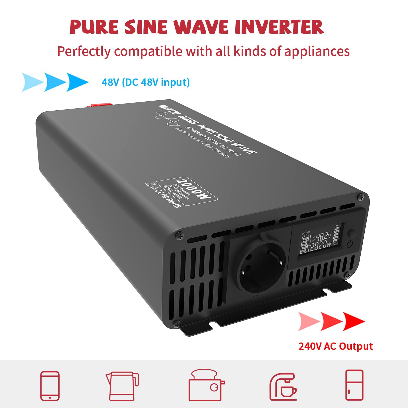
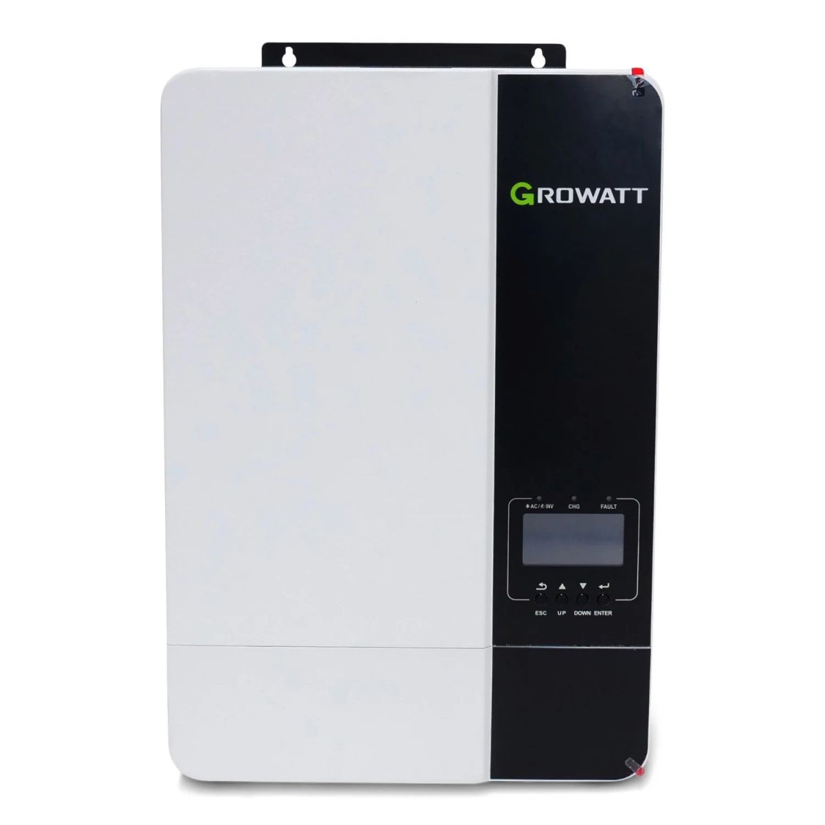
So I went want back to the drawing board and finally settled on an all-in-one Growatt SPF 3500 ES inverter. This inverter can accept about 4.5kW of PV power and provide about 3.5kW of AC power including a build in 48V battery option. This matches my system rather well as the maximum allowable single phase AC power for the wall-box is about 3,6kW.
Finally, I needed to find a Wallbox that a) can communicate via Modbus (explanation see below) and b) works with a single phase AC power supply.
My first choice was a VESTEL EVC04-AC11 Wallbox which, however, was just too smart to do the job. Despite some blog entries on the internet that this Wallbox can indeed be operated on a single phase, I did not get it to work reliably. The rather complex insides of the wallbox suggest that it measures 3-phase currents and voltages, possibly phase symmetry too. What might be a great feature-set in many cases, here it simply rejected my single phase set-up and indicated an undefined phase error. A perfect example of overcomplicating a very simple thing as an AC wallbox is essentially a glorified ON/OFF switch.
I therefore tried to find a wallbox that does away with all those unnecessary complexities, simply managing the car communication (via pilot signal) and switching on power if EV & wallbox are happy. Fortunately I found a great little Wallbox from Pracht Energy (Mono XT 1024) that fits the bill perfectly. It does not contain much more that a controller board, a DC capable RCD (Type A EV) and a high powered AC switch.
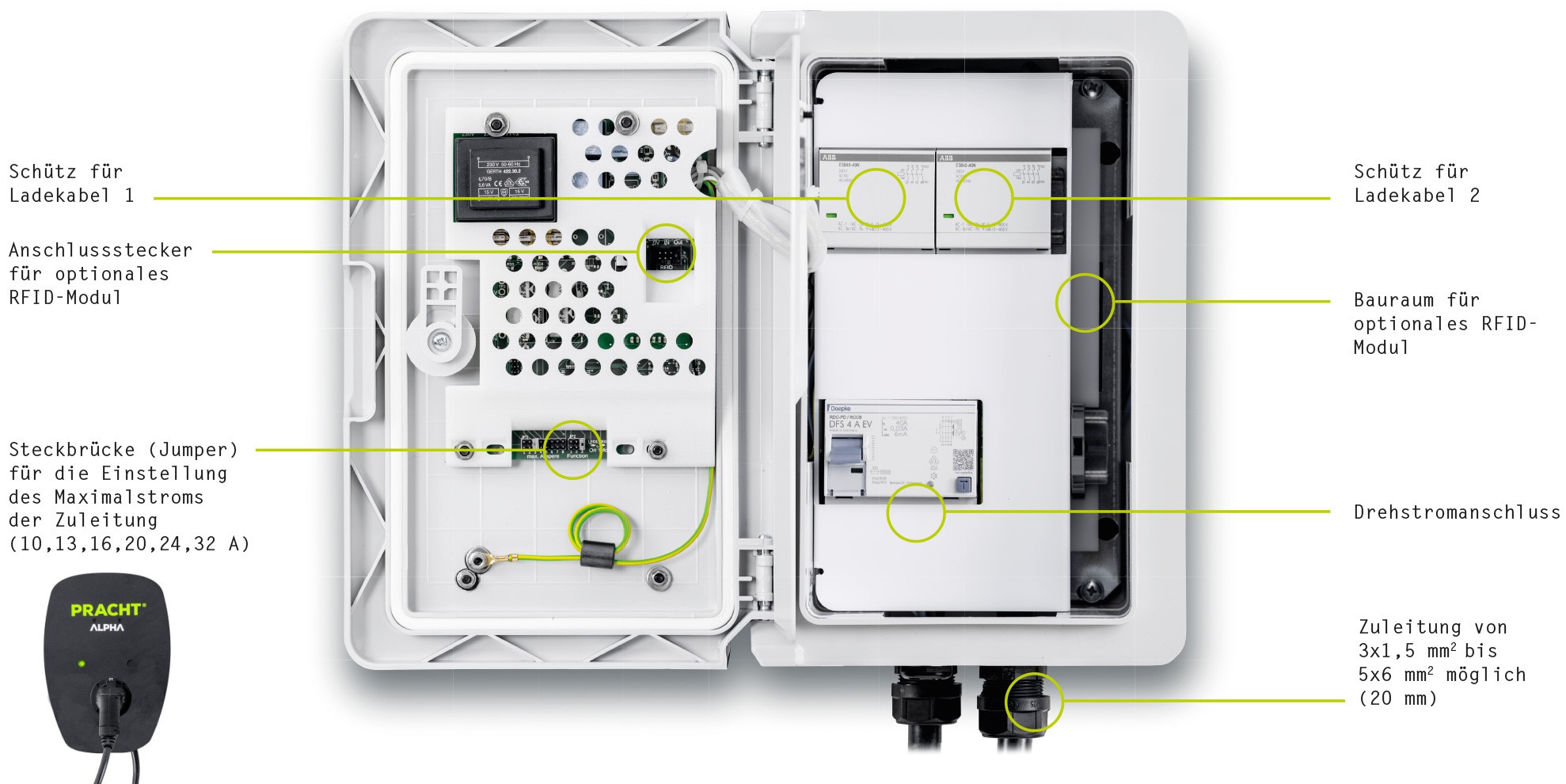
Initially it refused to charge my hybrid car but after some back and forth with the very friendly support center I received a brand new controller board with up-to-date software that completely solved the issue. Big shout-out to Pracht Energy - very happy with their product! (I'm not associated with them in any way - dual charger version shown here but mine looks similar inside)
Set-up, controller & charging strategy
Connecting the battery to the inverter requires the following configuration steps. First set program 5 to LI for Li-Ion battery. Then set program 36 to protocol 51 and set the DIP switches 5+6 on the battery to ON (rest OFF). Finally connect the communication cable between the inverter "BMS" port and the battery "CAN" port. Now the inverter should show the correct battery SOC (state of charge) in %. Connecting all the components electrically already gives you a working system where the Growatt inverter charges the battery, manages the SOC and provides AC to the Wallbox.

We could stop here but I wanted to optimise the charging process a bit so the charging power is matched to the generated PV power. Why does this matter? If the charging power for the EV is set to a constant (the wallbox has some configuration jumpers for that purpose) that is lower than the current PV output, the surplus energy will first be stored in the battery and then wasted when it is full. If charging power is set too high, it will quickly drain the battery and frequently interrupt the charging cycle.
To remedy this we need to control the power that goes to the EV depending on how much PV power is available. Time for some software (see Arduino code for the project in the files section) and a microcontroller (I used an ESP32 for this) to communicate to the inverter and wallbox via Modbus (Modbus spec for inverter and wallbox also in the files section) .
The generated PV power is now simply read from the inverter, divided by the line voltage and sent to the wallbox as a charging currently limit every few seconds or so.
But what happens if there is very little or no PV power? Then we charge the EV with the minimum allowable charging power of 1.3kW until the battery is down to about 30% - otherwise we could only charge if it is sufficiently sunny.

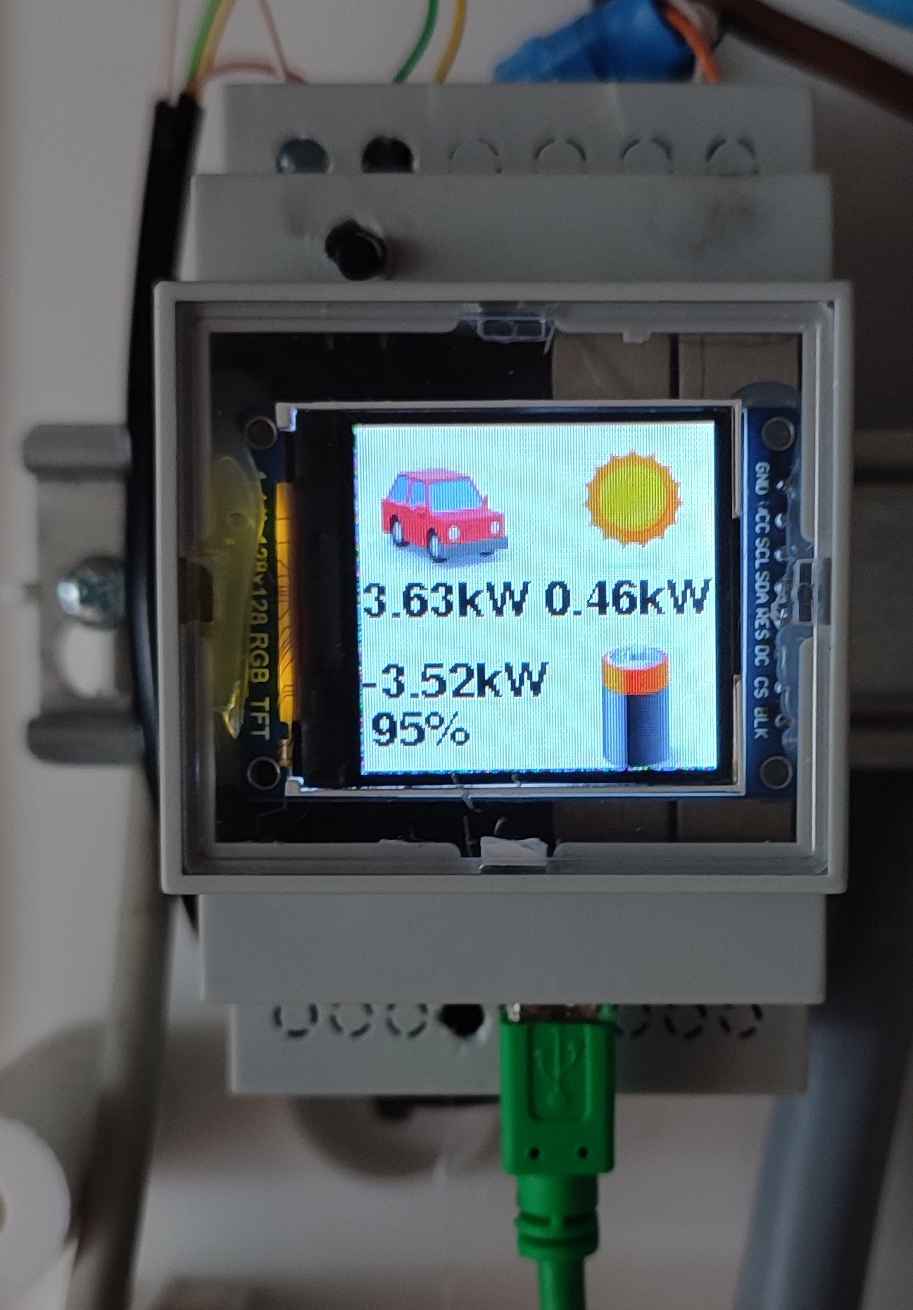
Once this worked, I noticed that the AC side of the inverter requires about 50W of idle-power which leads to a discharging of the battery over night. Since this may be issue in winter (where we want to preserve every little bit of energy) I installed a simple "demand" button below the wallbox that turns on AC if required. When the charging cycle is complete and the inverter is idle, the inverter AC side is turned off by the controller automatically. As a finishing touch I added a small display to the ESP32 so I can see what is going on with the system.
So far, the off-grid-charger has been working great. I can comfortably keep the batteries of both cars charged. In fact they only need charging a couple of hours every other day, essentially wasting most of the generated PV power. But off course it is summer and I presume that the system will produce significantly less power in winter - I will update this guide in spring with my experience if the design choices worked out ok.