 Pamungkas Sumasta
In this log I'm going to do deeper dive on the HW feature sets, components selection, interface and why it is there in the first place. You'll see that some of the HW design selection are either nice-to-have or must have. So in case you want to do some customization from the master design files, you can certainly do so with better background understanding. I'll start the explanation from the left hand side of the keyboard interface.
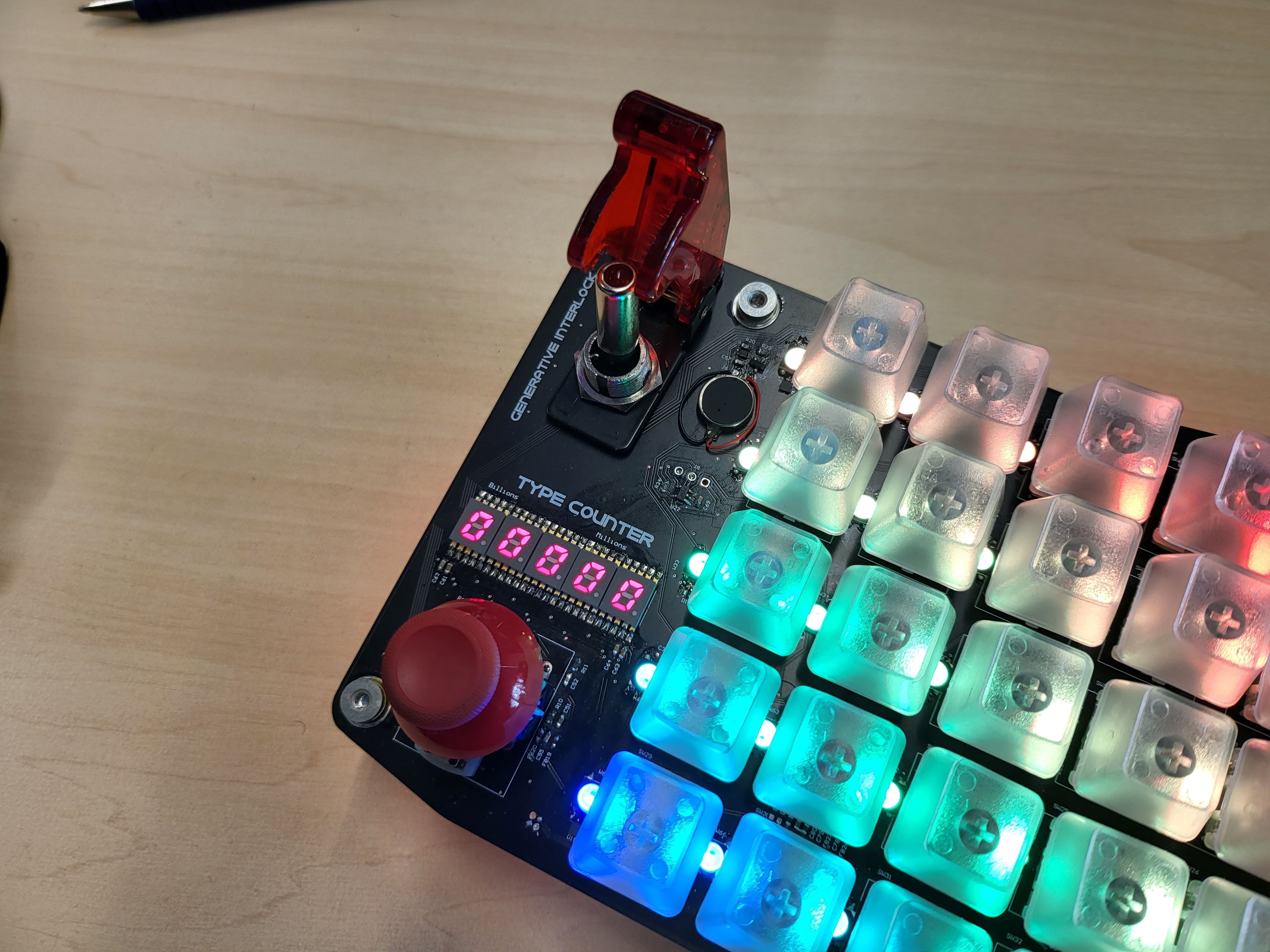
So the left hand side as depicted on the picture above, there are essentially four note-worthy features. Starting on the top left corner, you can see a rocket-switch which you'll often see in fighter jet. I specifically selected that particular one with two steps actuation primarily to signify the importance of us as a human/user to provide a confirmation and agreement on the contents that is generated by a Generative AI model. If you can read on the PCB silkscreen there, I labelled it "Generative Interlock", so as the name implies, it is essentially acting as a physical HW switch/barrier between providing access to the Bluetooth HID controller (ESP32) or not. In the diagram as you've seen, the main processor in the case of Generative kAiboard is an STM32F429, it manages interface directly to the Wiznet W5300 network interface, and it relies on co-processor ESP32 to manage Bluetooth HID command to the user end devices. In summary, in this case when the generative interlock is open, there will be no signal transmitted between the main processor to the co-processor thus preventing unwanted automation to your end-device. Alternatively, when the contents generated by the AI as it is buffered on the 5.5" screen is acceptable for you, the generative interlock can be closed thus enabling the streaming of the generated contents to your end-device.
Furthermore, on the right hand side of the generative interlock, there is a small circular disk which is essentially the left vibration motor. On this version of Generative kAiboard, there are 2 vibration motors placed on each end of the keyboard as you shall see later. The vibration motors are controlled directly by the main co-processor by PWM / GPIO Signals.
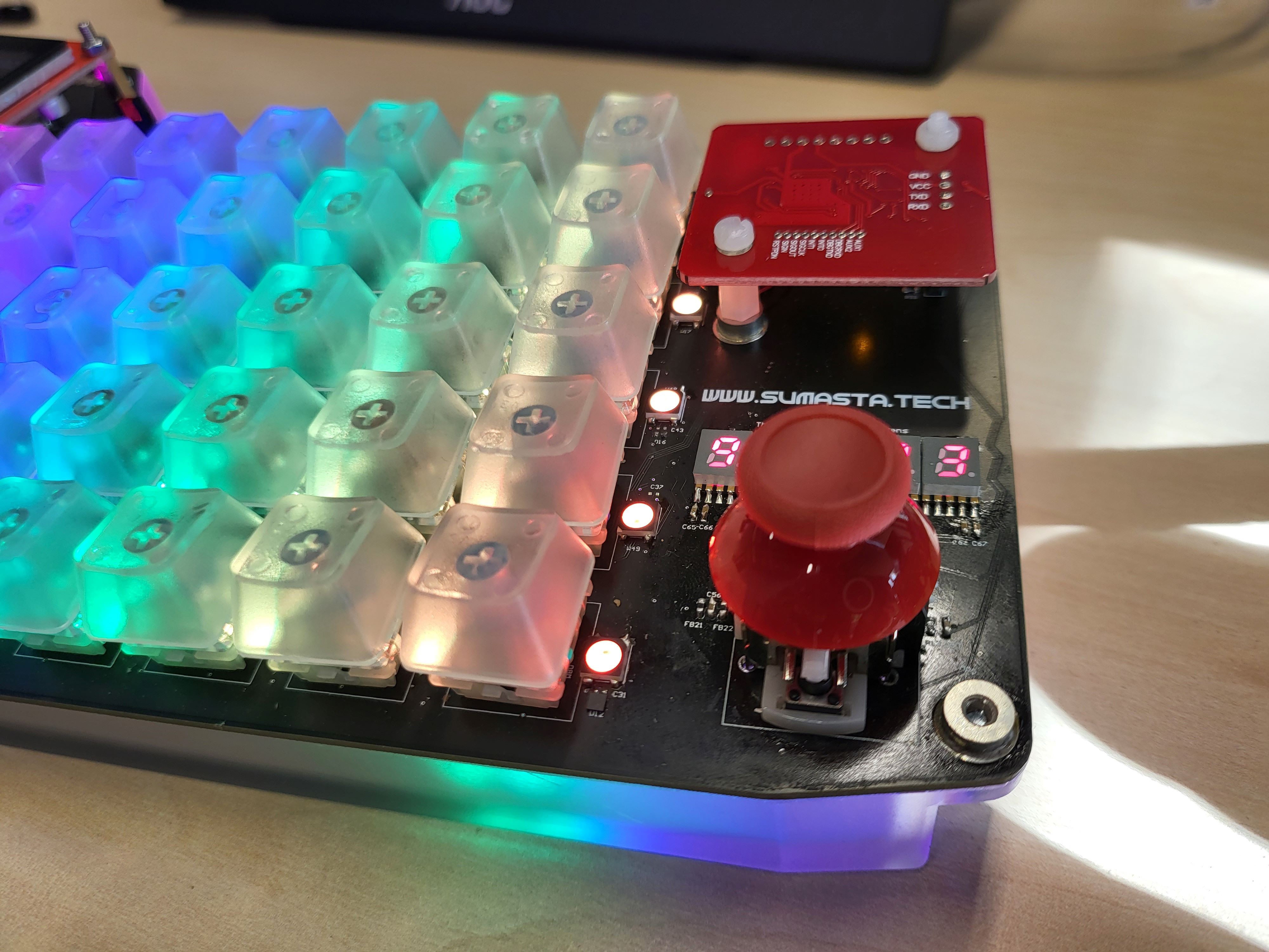
Below both of the aforementioned parts, you can see the type counter, to be precise, the first 5 digits of the type counter out of the 10 digits. The first five are located on the right hand side as you shall see. Having 10 digits it then allows you to log how many types the user has click and use the generative kAiboard up to 9.99 Billions. So let see how far that'll go. To me the main reason is simply to keep track and see how many clicks I have registered with the keyboard before something goes wrong. The cherry MX key switches claims guarantee of up to 100 million actuation, so we'll see about that. Also the type counter interfaces via SPI, there is a dedicated shift register underneath each of the 7-segment display. So no need to manage fast refresh rate on the 7-segment display from the main controller, it is latched individually.
At last below the type counter, I placed a 2-axis joystick, with a clickable button built-in. This is essentially an analog joystick you can find in game console controller, either Playstation or Xbox. It requires 2 analog input pins and 1 GPIO to make use of all the features. In the current configuration the joystick is connected directly to the co-processor (ESP32) instead of the main controller. Main reason is that because I expect the usage of this to be mainly for HID related functions, e.g. mouse or play/pause. Of course, via the co-processor you can provide commands / info to the main controller as well.
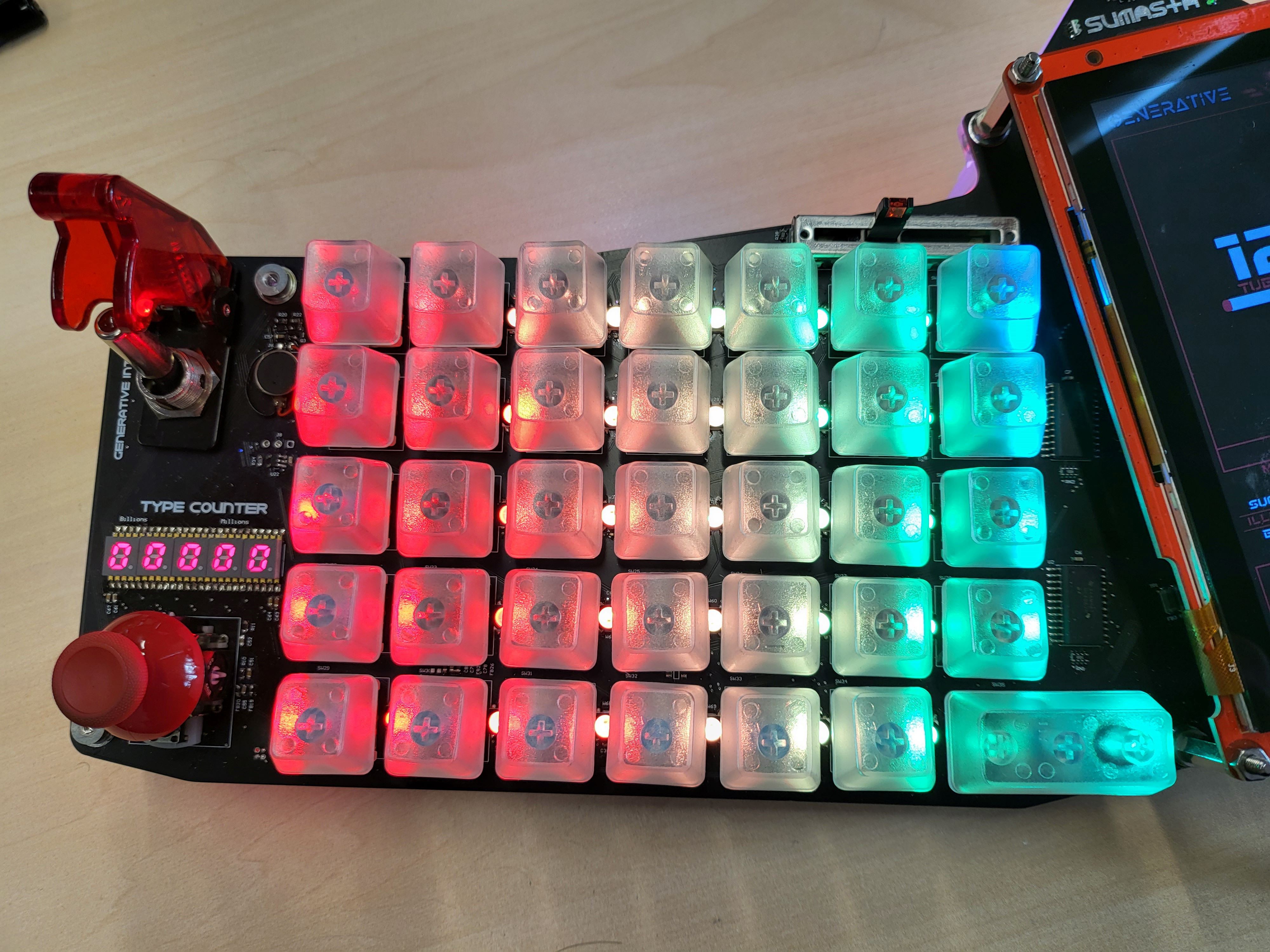
Moving on it's the left-hand-side of the split keyboard. There are 35 keys on each side, with symmetrical design in mind that adds up to 70 keys total. I opted for cherry MX for this for obvious reasons. However this time around I do a hybrid between Cherry MX brown and Blue. The printable characters I mainly prescribe using the Cherry MX brown which is much less noisy but also bit less tactile, while the non-printable characters around the edges of the keyboard I opted to use my favorite, which is the Cherry MX blue. It is good to know also that the key switches on this design is not directly connected to MCU GPIO or charlieplexed etc, but I decided to use multiplexer instead. Primary reason is to have individual single ended connection to the buffer and have less GPIO count use on the main controller side should I decided to opt to use other in the future.
Furthermore, in between the key switches, lays all the 80 x RGB WS2812b LED. The signal is daisy chained from the top left corner down to the bottom right corner of the keyboard. The LED is controlled by the co-processor in this case as well as I don't want to load the main processor with the light animation. Although, if you look at the schematic, there is a parallel bus with buffer connecting the input pins of the first WS2812b and GPIO of co-processor and main-processor. This way if needed, the LED can also be controlled by the main controller STM32.
As the cherry on top, a translucent keycaps are used. These are standard type you can now find and buy cheaply from aliexpress or so. Surely is personal preference, you can also opt to use for other colors / translucent level etc.
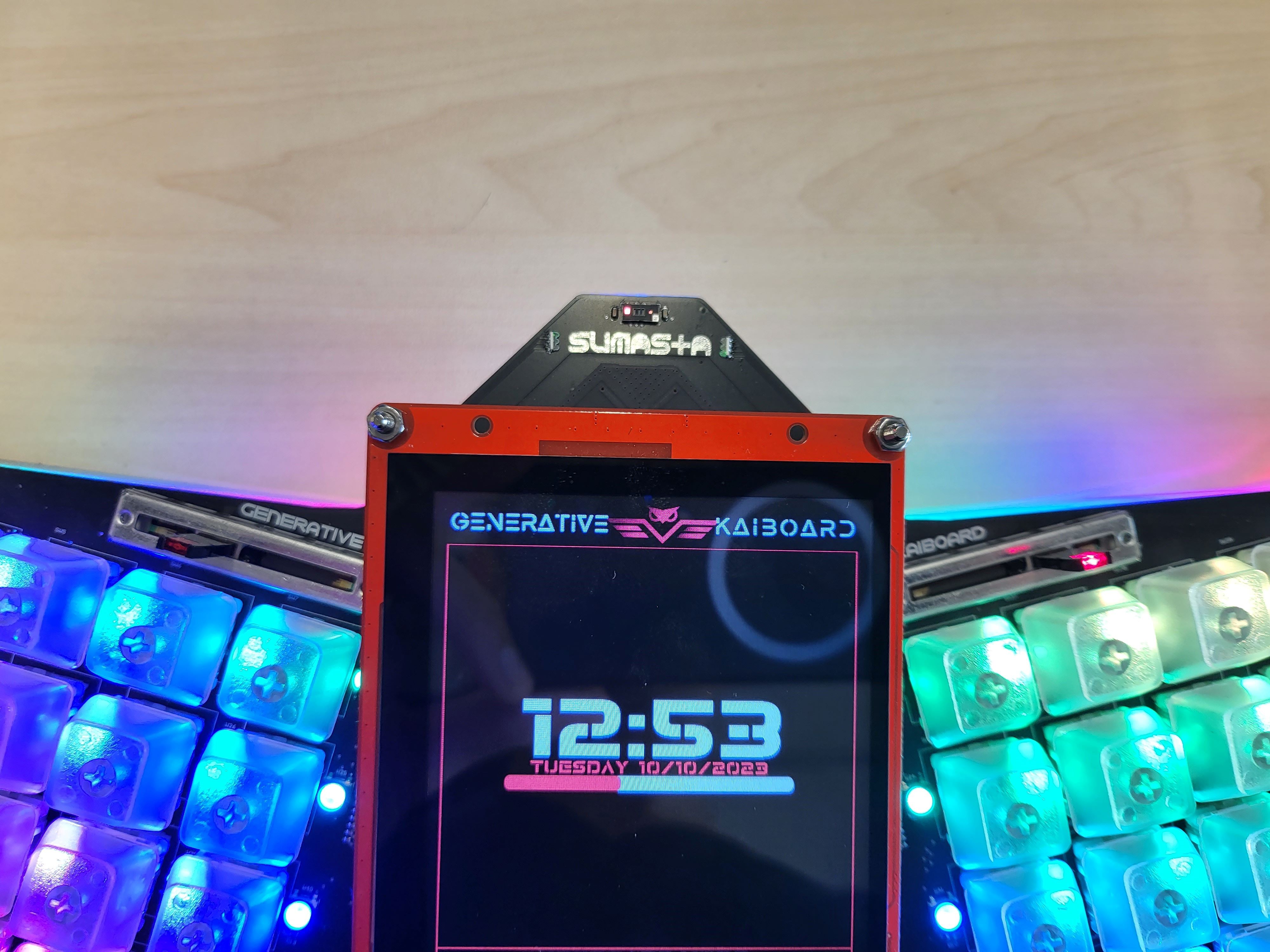
On the top center region, first thing you'll notice is obviously the 5.5" Screen. The screen is a Nextion intelligent series with built-in driver and controller. Micro SD card slot is also provided underneath the display. Furthermore, it has built-in capacitive touch panel allowing you to interact quite nicely with the display. The Nextion display is connected via UART to the main controller, but it is programmed independently via a connector on the top side of the display. Also via a UART connection to the PC. At last, underneath it has also driver for speaker and the speaker connection, allowing you to play audio and video quite easily. It is noteworthy to say that the display is not the cheapest type on the market, but considering the platform and IDE that it offers, it certainly is worth every penny.
Moving on the the sides of the display, on the left and on the right, tilted a bit, you can see 2 slider potentiometer incorporated on the generative kAiboard. These sliders are connected to the co-processor and for the moment, it is programmed to control the primary light intensity as well as the light animation. As the co-processor is managing all the 80 x WS2812b RGB LED, it makes sense to also connect the 2 potentiometer slider to the spare analog pins of the ESP32 co-processor module.
On the very top on of the keyboard, you can see the multizone time-of-flight sensors from ST. It is interfaced via I2C interface and it is intended for people presence detection as well as gesture detection. This particular sensor also is not a standard ToF distance sensor, but this particular one is a 8x8 multizone sensor which can provides you with distance information on 64 different zones at once. Pretty cool right!!?!
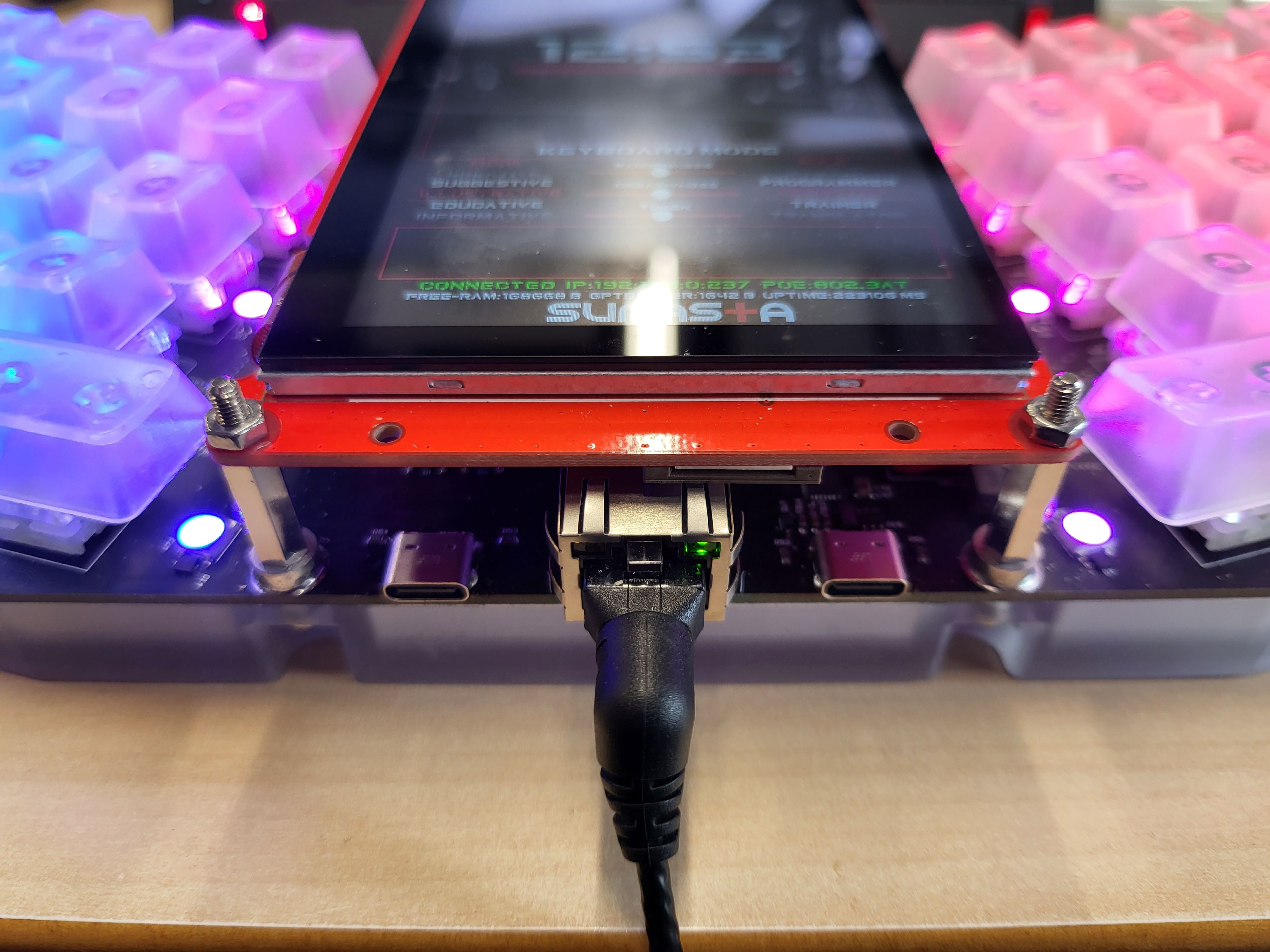
On a bottom middle section as you can see on the picture just above, there are three connectors exposed to the outside world. The first and foremost is the RJ45 Ethernet connector which provides both data/internet and power. I strive for neatness on this build, so I tried to minimized cabling as much as possible. With PoE this is made possible. Moreover, not only a standard PoE, but the Generative kAiboard incorporated PoE+ which is compliant to IEEE802.3AT standard which can accepts power up to ~25W in this particular case. And on the board there are mainly two power rails after the PoE module, and that is 5V and the 3.3V.
On the left side of the RJ45 jack, you have the first USB-C connector which essentially connects to ST-Link inside the Nucleo board. This is pretty much just a connector extension from the ST Nucleo board inside the unit, nothing more and nothing less. As you know, having an exposed programming / debugging connector is really2 important and handy especially for development process.
In addition to that, on the right side of the RJ45 connector, there is another USB C connector which connects to the Silicon Labs USB-to-Serial. It interface to the co-processor ESP32 for programming and serial debugging. I didn't plan it in initially to be honest, but last minute decision of adding this built-in on board is really crucial and safe a lot of hassle for programming and testing.
It is important to note also there is no USB PD built-in on here, so you surely cannot power the whole board via either of the USB-C. It is already on my list for the next HW iteration.
At the very end, on the right hand side of the generative kAiboard you have few more HW features. Quite similar to what we have on the left hand side, there are an additional Joystick and the first 5 digits of the type counter. They are all interfaced the same way and connected to the same controller as the one the left. While the left joystick is used for media control, the right joystick is currently prescribed for keyboard arrow control.
On the top right corner in the meantime, the NFC tag reader is incorporated. It is based on PN532 Chip and currently interfaced via I2C to the main controller. The main function is essentially for authenticating the and unlocking the keyboard etc.
Hidden below the NFC tag, there is an additional vibration motor as well as external EEPROM that is also connected via I2C to the main controller.
Well, I hope that covers all of the HW features of the Generative kAiboard!
Discussions
Become a Hackaday.io Member
Create an account to leave a comment. Already have an account? Log In.