In the last post we talked about the command module block (CMB) frame design. Next up are the PCBs. Each CMB has a single PCB mounted on the bottom of the frame. It holds a user interface element such as a switch or potentiometer, along with a pin header and a small connector for interfacing to the outside world. You can see the PCB at the bottom of the exploded view.
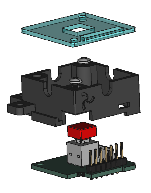
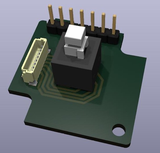
This particular PCB holds a pushbutton switch. When assembled, the switch's button cap protrudes through the square opening in the top cover. The pin header will line up with the slot in the cover to provide access for installing jumper cables.
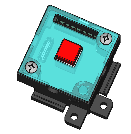
I've also designed a few others to have a nice assortment of UI elements:
- Pushbutton PCB - Holds a DPDT pushbutton switch with removable button caps (red, white, or black). The switch is available in momentary and latching versions.
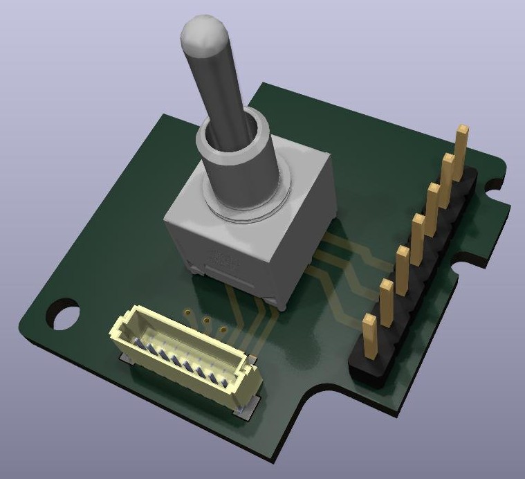
- Toggle PCB - Holds a mini DPDP toggle switch. Great for retro stuff and general prototyping.
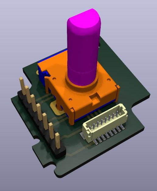
- Dual Gang Potentiometer PCB - Holds a dual-gang potentiometer. Great for analog circuit prototyping and for general knob based control.
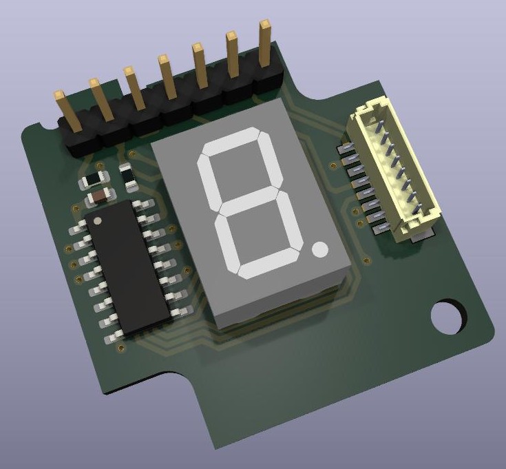
- Seven Segment Display PCB - Holds a 7-segment LED display with a shift register based driver. These can be cascaded to form larger displays. General purpose retro-ish display.
All of the PCBs being fabricated. For now, here are some nice renders from KiCad.
Discussions
Become a Hackaday.io Member
Create an account to leave a comment. Already have an account? Log In.