 Michael Wessel
Alright Microtronic, I finally know what you are doing!
An additional motivation for this project is to make the Pico act as a co-processor - see, if the Pico knows the current op-code that is being executed (and the address / PC, obviously), I can make the Pico act on behalf of this op-code and implement "extra semantics" for some op-codes. What's "extra semantics" you might ask? Well, unfortunately, all 12bit op-codes are already occupied and already have a semantics in the Microtronic... but, some of these are "vacuous" and don't do anything meaningful - they are basically no-ops! For example, 0<x><x> copies register <x> onto itself. Same for "add 0 to register <x>", "subtract o from register <x>" - no Microtronic program is using these, and I can just grab them and give them extra-semantics to do something meaningful.
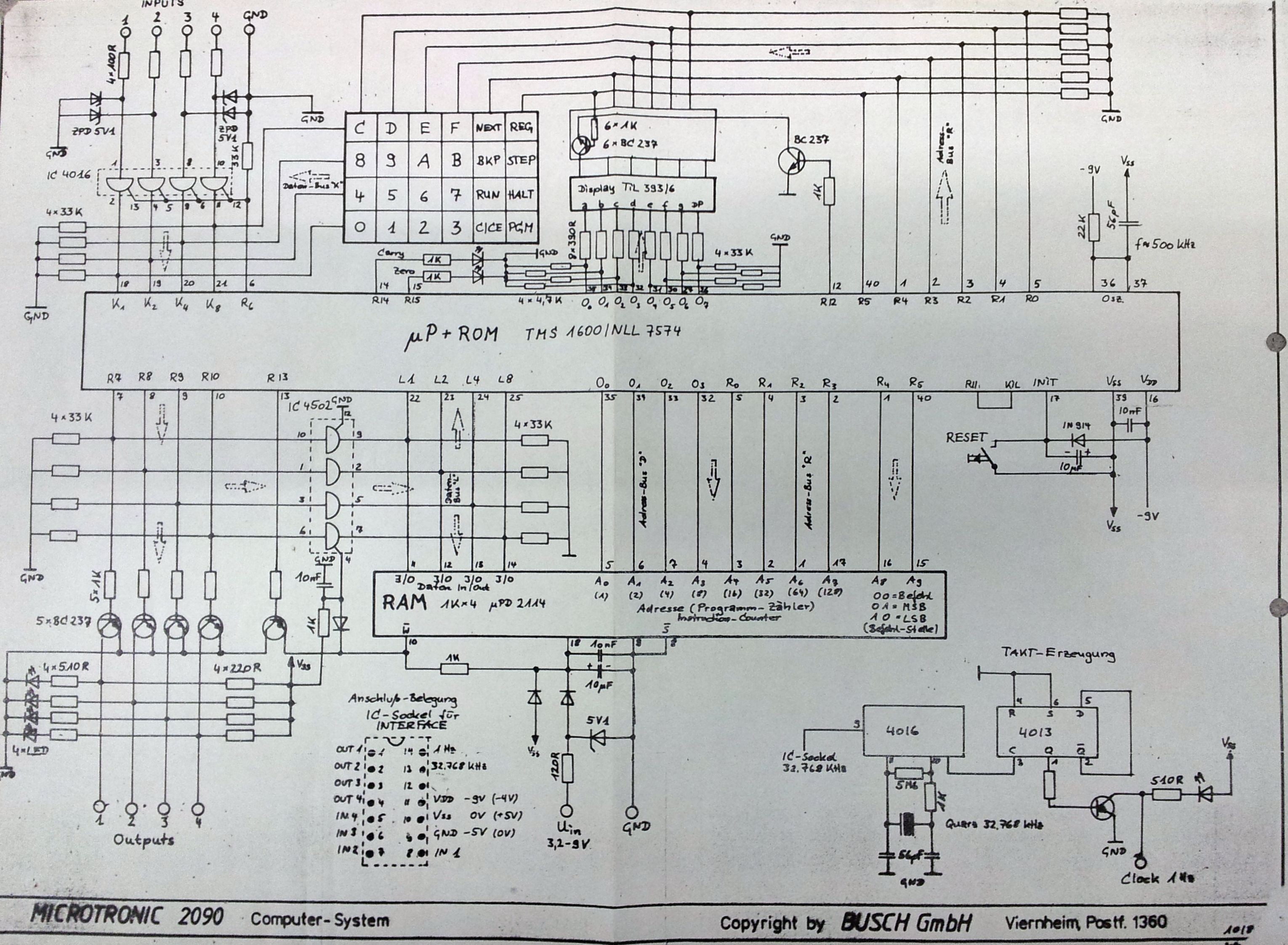
Looking at the schematics, we can see that the SRAM is addressed using the same GPIO lines that are also utilized for accessing the LED display and keyboard:
So how do we distinguish the SRAM accesses from all this additional activity on the GPIO "bus"? It took me many hours until I finally had a way of reliably detecting SRAM accesses.
A 12bit op-code starting at address <adr> is represented as follows in Microtronic SRAM:
the first nibble is at <adr>, the second nibble at <adr> | (1 << 9), and third nibble at <adr> | (1 << 8).
My original idea was to simply implement a state machine that "tracks" the addresses as they show up on the bus: start in state 0, when <adr> arrives, go to state 1; when in state 1, and <adr> | (1 <<9) arrives, transition to state 2; when in state 2 and <adr> | (1 << 8) arrives, you have identified the SRAM access; reset to state 0. Right idea? Wrong!
The major problem with this approach is that the automata gets into wrong states - it is impossible to tell whether the transition from state 0 to state 1 is triggered by a real SRAM access, or by display multiplexing or keyboard scanning activities. Hence, the automata would sometimes get stuck, i.e., it transitioned into a wrong state and was waiting for a next adr pattern that didn't arrive as anticipated. I then thought, ok, let's reset the state when needed then (i.e., backtrack). But this strategy then had the problem that I would "miss" certain transitions, i.e., the automata wasn't getting stuck anymore, but when backtracking, I had already missed part of the address sequence. In addition to these "backtracking transitions" I then also started to incorporate timing-related info into the transition conditions, and things got more and more complicated, but I found no way of not "missing" certain addresses from wrong transitions and backtracking.
I had gotten myself into a dead end. Then I erased everything and started all over!
This time I had the right idea - I realized that I could only "retroactively" identify if an already presented sequence of addresses is part of the 12bit SRAM access pattern, but could not do so "proactively" (the automata approach had failed for this reason). I then simply kept a log ("sliding window") of the last four GPIO addresses: in addition to the current address in variable adr, I would also do a adr4 <- adr3, adr3 <- adr2, adr2 <- adr1, adr1 <- adr for each new recognized address change. By constantly scanning this window I then managed to identify the SRAM access with the following conditions:
if (adr4) {
  if (adr & (1 << 8)) {
    if (adr3 & (1 << 9)) {
       if ( (adr & adr3 ) == adr4) {
           // SRAM ACCESS FOUND!
       }
    }
  }
}
However, I also needed to add one more hardware-mod - by routing the R12 signal from the TMS1600 which is used for multiplexing the display segments over a transistor (see schematics above), I could also filter out all address patterns that would "light up the segments". Luckily, the Microtronic has a via for that signal, and I could simply solder in a pin from one of these breakout pin-headers, so I didn't need to disassemble the whole thing and it's also looking neat. A DuPont wire is used to route it into the Pico, again over a voltage divider. It took a bit of time again to find the right resistors for the divider, but in the end, I could now at least also exclude the "active" display accesses. I still don't have a way of excluding the keyboard scanning accesses, but that's ok. It works.
The only problem with the above condition / approach is that I cannot detect adr 0. But that's OK; it's a little bit ugly for program debugging, but good enough for op-code extensions (we just can't have an extended op-code at adr 00 then). It works for all other addresses. Sometimes, a fresh approach and change of perspective is needed in order to make progress!
I also added an OLED display to visualize what the Microtronic is doing, and utilized the 2nd core of the Pico to constantly refresh / update the display. First I tried using the same core that does the SRAM emulation, but this is no longer fast enough then (timing is critical here!). This is great for debugging! I'll also add mnemonics to the display soon.

Well, great, I can now implement the "Pico co-processor" idea! And easy thing to do is to arrange for the vacuous op-codes to perform extra-side effects. For example, "0<x><x>" can be intercepted by the Pico and it could, for example, mean "play note <x> on the loudspeaker". We have just added a sound op-code to the Microtronic! Or it can mean "send character <x> to the OLED display" - the Microtronic can now display text messages! I think the original designers might be surprised by this :-)
It's a little bit more complicated to implement op-codes that compute something that the Microtronic will then pick up. For example, imagine that the op-code "0<x><x>" means "calculate the square of <x> and write it to registers E,F". As the Microtronic is a Harvard architecture, I cannot write the 32 4bit registers ("Microtronic register file") with the Pico directly. SRAM is only for program memory, not for registers. But, I can inject a program segment with the Pico that, when executed by the Microtronic, will modify the register values to represent the computed value - "data as program"! Say the op-code "033" is detected by the Pico, now meaning "compute the square of 3 and write it to registers E,F!" If the current PC is adr, then the Pico will now first compute the square of 3, and subsequently, starting from adr+1, "inject" a sequence of MOVI (Move Immediate, i.e., move a constant to a register) instructions that write the Pico-computed values (0 and 9) to the appropriate registers (E and F). Hence, the Pico will present 10E at adr+1 to the Microtronic, and 19F at adr+2. The Microtronic will execute these, and the Pico-computed values will appear in the appropriate registers. At adr+3, the Pico will present a JMP / GOTO to adr+1. After the Microtronic has execute this last JMP / GOTO, the Pico continues presenting the original program from SRAM to the Microtronic again. The "injected" program sequence has been executed, and the Microtronic continues execution of the original program as usual. But has now the computed square 09 in its EF registers. Magic!
Next, I am going to work on the SDcard for SRAM images.
Discussions
Become a Hackaday.io Member
Create an account to leave a comment. Already have an account? Log In.