 Jon
JonThe PCBs arrived and everything went together smoothly.

The dials had to be installed first because the top/bottom LEDs were slightly too close to the switch body and wouldn't let the dials sit flush with the pcb when installed first.
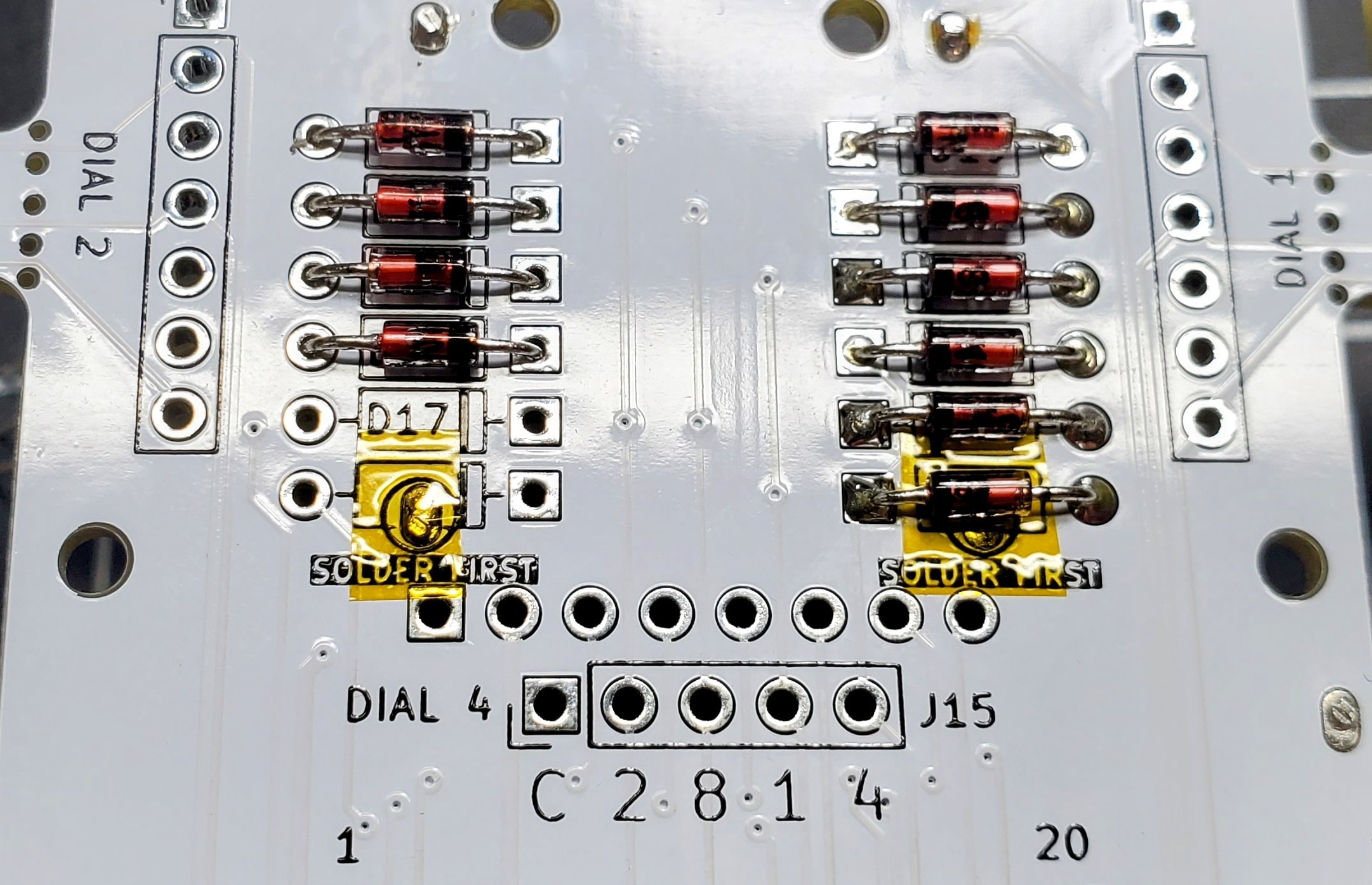
The Magnetic Reed switches have a solder joint under two diodes and needed to be installed before the diodes. I covered the joints with Kapton tape even though the diode body shouldn't be conductive.
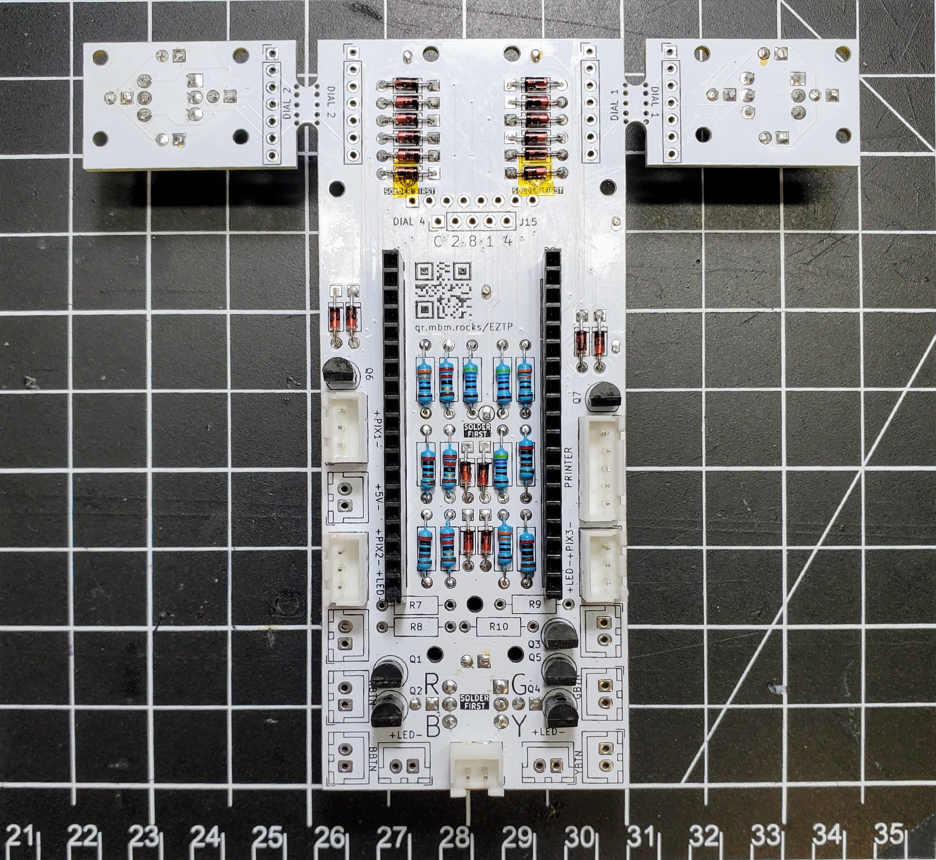
After the reed switches were installed, I added the resistors, transistors, and microcontroller socket.

I clamped the PCB to the table to make sure the cable plugs were completely flat. I only installed sockets for connections going to things mounted to the body. The buttons and LEDs attached to the face plate will be wired directly to the board.
Discussions
Become a Hackaday.io Member
Create an account to leave a comment. Already have an account? Log In.