 Abraham Limpo
In the end I decided to go for the "mess of wires". The good thing about this approach is that the board is extremely simplified, as you can reroute the wires as you want on the connectors. Here's the diagram:

There are two JST 5 connectors on one side, one for data and one for power, plus other two JST connectors for the buttons on the other side. I also noticed that at some point the reset button started to fail (these cheap clones...) so I removed it and put a nice button on the extra space of the board.
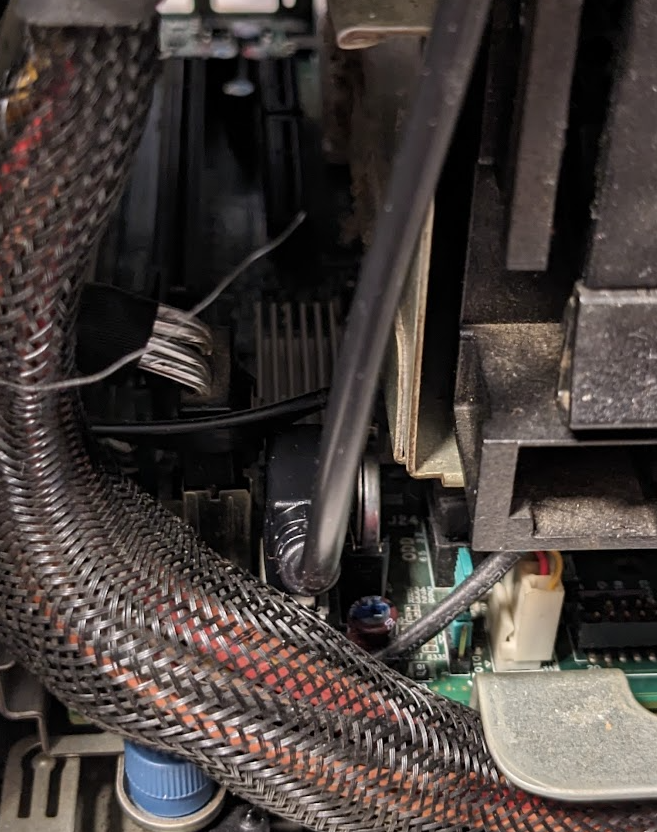
And here is how it looks in the end:

Yeah, so much for cleanliness. The board is mounted with double tape adhesive above the SSD hard drive. The USB cable is routed below the printed box through a hole in the case where the HDD power cables are stored. From there it goes to an internal USB connector (that originally was meant to put a USB boot stick for simple OS's). As I mentioned in the previous post, the 20cm cable is WAY too short. If someone follows these instructions I would say to use a normal cable and route it through the back. It will also make assembly and disassembly much easier.
To complete the assembly, we screw the top part to the faceplate and secure it to the bottom, and we can close the computer.

So now we only need to know how to make them talk to each other.
Discussions
Become a Hackaday.io Member
Create an account to leave a comment. Already have an account? Log In.