 bryan.lowder
So SKELLY required an activation "button press" very shortly after power was supplied. This meant a delay, so I reached for every hobbyist's favorite timer, the 555 IC. It had been a very long time since I had messed with a 555 timer IC, so I reviewed it, and quickly understood why the chip is so popular. In brief, when the voltage on the TRIGGER input falls below 1/3VCC, the output switches HIGH, and when the voltage on the THRESHOLD input goes above 2/3VCC, the output goes LOW and the open-collector DISCHARGE pin shorts to ground. There are many many ways to hook up various RC circuits to this to perform all kinds of tasks.
The relays I obtained ran on 3 V so that they could be energized with the 4.5 V power source for SKELLY (with appropriate current reduction). I had assumed that the 555 timers I obtained would be able to drive the relays directly, but no such luck-- the IMC7555 CMOS chip I obtained had very flexible voltage requirements, but could only source/sink 1.0mA/3.2mA respectively.
I had a BJT transistor lying around and found it could drive the relay just fine, triggered by the 555 output. Examination proved the transistor to be a NPN (yes, I didn't bother checking first) 2N4401 . I found a second one nearby so this became my official transistor. Would a MOSFET be better? Well, the voltage control would probably make it a little more complicated.
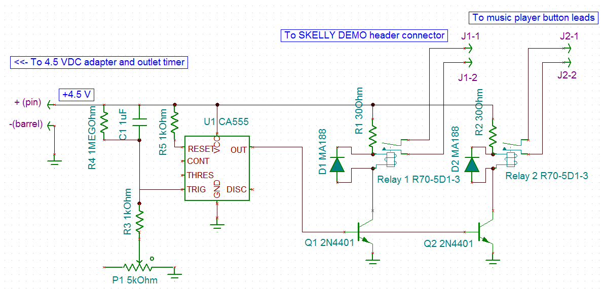
The schematics for the simple control board are shown above. The control board is energized only when the outlet timer turns on, switching on the 4.5VDC adapter. The 555 timer is wired to turn on for an indefinite period after a brief delay. The RESET input is tied HIGH to prevent resetting the internal flip-flop. C1 and R3 + P1 form a time-dependent voltage divider: C1 is empty when power is supplied, which will cause the voltage at the 555's TRIGGER input to start high and eventually fall to zero. The variable resistor allows some adjustment of the delay time.
As soon as the TRIGGER input falls below 1/3 VCC (about 1.35 V), the OUT pin goes HIGH, switching on both transistors Q1 and Q2. This then pulls current through the respective relay coils, closing the switches. The resistors drop the voltage to the rated 3V.
The first relay is connected to the DEMO button header on SKELLY and substitutes for the DEMO button. The second relay is soldered in place of the button that activates the music player. Hence both SKELLY and the music start at the same time, but shortly after the DC adapter switches on.
When the power switches off, the relay coils generate a flyback voltage. D1 and D2 short this voltage to prevent damage to other components. The charge on C1 is allowed to drain through the 1 Megohm resistor, which is high enough not to interfere with the short-term timing, but allows discharge over the several minutes before the next turn-on.
To be brutally honest, I don't recall the exact values of the resistors I used, but they were similar to the values listed. The current through the coils was lower than expected, but they snapped closed with no trouble.

The control board was soldered up on some perfboard that was NOT identical to a breadboard. I might have been tempted to keep it on a breadboard, but neither these relays nor the alternative relays I had handy would fit properly on a breadboard. I'm unsure why electronics manufacturers decided this would be a great way to do things.
I soldered a barrel connector onto the perfboard. This was intended to connect to the splitter for a convenient way to direct power to both SKELLY and the control board without wrecking cables or soldering/crimping. Unfortunately, I picked the wrong cable "sex", but MIBRO had a male-to-male adapter that saved the day.
Why relays? See next log.
Discussions
Become a Hackaday.io Member
Create an account to leave a comment. Already have an account? Log In.