 Hazal Mestci
Software
To build your own autonomous robot, you need the following software:
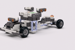
Creepsy, with sensors and spooky sounds, navigates obstacles, identifies guests, and moves towards to scare them at spooktacular gatherings.
Already have an account? Log in.
To make the experience fit your profile, pick a username and tell us what interests you.
Software
To build your own autonomous robot, you need the following software:
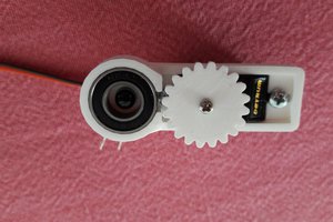
universalBracket V3.SLDPRTUltrasonic holder CAD designsldprt - 379.30 kB - 10/31/2023 at 21:53 |
|
|
ultrasonicBrkt.STLUltrasonic holder CAD designStandard Tesselated Geometry - 148.32 kB - 10/31/2023 at 21:53 |
|
|
spooky-thunder.mp3Spooky sound the code uses as the robot looks for a person or follows a personMPEG Video - 3.66 MB - 10/31/2023 at 19:53 |
|
|
scream.mp3Spooky sound the code uses as the robot looks for a person or follows a personMPEG Video - 64.58 kB - 10/31/2023 at 19:53 |
|
|
possessed-laughter.mp3Spooky sound the code uses as the robot looks for a person or follows a personMPEG Video - 131.43 kB - 10/31/2023 at 19:53 |
|
Follow the wiring diagram below to wire together your Raspberry Pi, buck converter, USB camera, motors, motor driver, ultrasonic sensors, and battery:
The Creepsy robot uses an assembled SCUTTLE Rover base with some modifications: Creepsy does not use the camera that came with the SCUTTLE Rover because the cable is not long enough to allow the camera to be attached to the top of the robot. Additionally, Creepsy also does not use the encoders or the batteries that come with the kit. These changes are reflected in the wiring diagram.
One thing that the diagram does not reflect is the speaker. Add the USB speaker to the USB port on the Raspberry Pi, on the port that's not being used by the camera.
In the Viam app, create a new robot and give it a name like Creepsy. Follow the instructions on the Setup tab to install viam-server on your Raspberry Pi and connect to your robot.
Navigate to the Config tab of your robot’s page in the Viam app. Click on the Components subtab.
Add a board component to represent the Raspberry Pi:
Click the Create component button in the lower-left corner of the page. Select type board and model pi. Enter local as the name, then click Create.
You can name your board whatever you want as long as you refer to it by the same name in your code.
Add your right motor:
Click Create component in the lower-left corner of the page. Select type motor, then select model gpio. Enter rightMotor as the name, then click Create.
After clicking Create, a panel will pop up with empty sections for Attributes, Component Pin Assignment, and other information.

In the Board drop-down within attributes, choose the name of the board local to which the motor is wired. This will ensure that the board initializes before the motor when the robot boots up.
Then set Max RPM to 100 and enable direction flip.
In the Component Pin Assignment section, toggle the type to In1/In2. In the drop downs for A/In1 and B/In2, choose 15 GPIO 22 and 16 GPIO 23 corresponding to the right motor wiring. Leave PWM (pulse-width modulation) pin blank, because this specific motor driver’s configuration does not require a separate PWM pin.

Now let’s add the left motor which is similar to the right motor. Add your left motor with the name “leftMotor”, type motor, and model gpio. Select local from the Board drop-down, set Max RPM to 100, and configure the motors pins as A/In1 and B/In2 corresponding to12 GPIO 18 and 11 GPIO 17 respectively (according to the wiring diagram), and leave PWM blank.
Next, add a base component, which describes the geometry of your chassis and wheels so the software can calculate how to steer the rover in a coordinated way:
Click Create component. Select base for type and wheeled for model. Name your base creepsy-base, then click Create.
In the Right Motors drop-down, select rightMotor , and in the Left Motors drop-down select leftMotor. Enter 250 for Wheel Circumference (mm) and 400 for Width (mm). The width describes the distance between the midpoints of the wheels. Add local, rightMotor, and leftMotor to the Depends on field.
Add the camera component:
Click Create component. Select type camera and model webcam. Name it cam and click Create.
In the configuration panel, click the video path field. If your robot is connected to the Viam app, you will see a drop-down populated with available camera names.
Select the camera you want to use. If you are unsure which camera to select, select one, save the configuration, and go to the Control tab to confirm you can see the expected video stream.

Then make it depend on local so it initializes after the board component.
Add a sensor component:
Click Create component. Select type sensor and model ultrasonic. Name your sensor ultrasonic, then click Create.
Then fill in the attributes: enter 38 for echo_interrupt_pin and 40 for trigger_pin, according to the wiring diagram. Enter local for board.
You have to configure the other ultrasonic sensor. For each of the additional ultrasonic sensors, create a new component with a unique name like ultrasonic2 (where “2” indicates it’s the second sensor), type sensor, and model ultrasonic. In the attributes textbox, fill in the trigger_pin and echo_interrupt_pin corresponding to the pins your ultrasonic sensors are connected to.
While this tutorial and associated code demonstrate using 2 ultrasonic sensors, you can change the amount based on your preference.
With the components configured, navigate to the Control tab. On the control tab, you will see panels for each of your configured components.
Click on both motor panels and check that they run as expected by clicking RUN.

Click on the base panel and enable the keyboard. Then move your rover base around by pressing A, S, W, and D on your keyboard.
You can also adjust the power level to your preference
To see your camera working, click on the camera panel and toggle the camera on.

Click on your sensors panel and test that you can get readings from all of them.
Click Get Readings to get the distance reading of the sensor.


 middelbeek
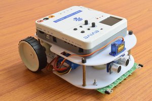
 evive toolkit
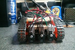
 velorider