 Guy Dupont
I'm working on a schematic for this, but it's taking a while since I'm using so many "module" parts that dont have symbols. In the meantime, here's a description of what's going on:
- Power comes from a rechargeable 12V battery, which is cut off from the rest of the circuit by the chonky SPST power switch.
- After the switch the 12V is fed directly to the thermal printer's power input, and also into a regulator module that drops it down to 5V.
- The XIAO:
- is powered by 5V
- Sends out printer commands using it's UART
- Speaks the the web server via WiFi
- Drives the WS2812 with GPIO D0 (and powers it via it's 3.3V pin)
- Speaks to the Tiny Code Reader via I2C (and powers it via it's 3.3V pin)
- This printer does not accept normal TTL logic input (without modification) - it needs RS232. So a Max3232 takes the UART output from the XIAO and converts it to RS232 for the printer.
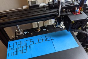
 Travis Bumgarner
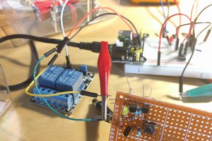
 Dave
Dave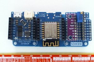
 tucanae47