 Mrinnovative
Hello friends this time I have made a arduino based label dispensing machine
I have used stepper motor and IR sensor in this project.
I also used a custom-made PCB in this project.
This project is great learning for 3D printing, Mechanics, electronics and programming
Label dispensing is a critical point in many industries like, E-comerce, FMCG, automobile and many more.
if you have small or large business you definitely preparing parcel of you final goods to dispatched.
for that parcel, you definitely need a label sticker to paste on the parcel. it may be a warning, invoice, receipt, or thanks for shopping wish.
Imagine you have hundreds of parcel to dispatch and manually pealing label one by one is very tough job to do.
So here my this auto label dispenser machine can help you to dispense label for you. and make our dispatch prosses fast


Arduino Nano:
- The Arduino Nano is a compact microcontroller board that serves as the project's brain. It's the central control unit responsible for executing the desired actions based on input and programming.
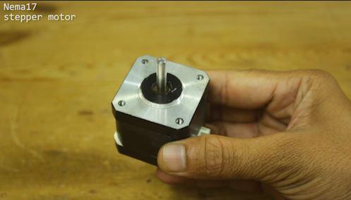
Nema 17 Stepper Motor:
- The Nema 17 stepper motor is a powerful, precise motor used for controlled motion in your project. It's often used in applications requiring accurate positioning, like 3D printers and CNC machines.
A4988 Stepper Motor Driver:
- The A4988 stepper motor driver is an essential component for driving the Nema 17 motor. It interprets signals from the Arduino and controls the motor's movement, providing the necessary power and precision.
20 x 20 Aluminium Profile:
- The 20 x 20 aluminum profile is a structural element that forms the framework for your project. It provides stability and a rigid structure to support various components and ensure proper alignment.
3D Printed Parts:
- 3D printed parts are custom-designed components created using additive manufacturing technology. These parts are unique to your project and serve specific functions, such as mounting brackets or enclosures.
5mm Smooth SS Rod:
- The 5mm smooth stainless steel (SS) rod may be used as a linear guide or structural support element in your project, offering smooth and low-friction motion for certain components.
8mm Smooth SS Rod:
- The 8mm smooth stainless steel rod serves a similar purpose as the 5mm version but with a larger diameter, providing increased load-bearing capacity and stability.
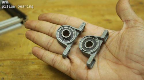
8mm Pillow Bearing:
- The 8mm pillow bearing is a type of bearing that supports the smooth rods, reducing friction and ensuring the smooth movement of parts along the rods.
8mm Timing Belt Pulley:
- The 8mm timing belt pulley is used to transfer rotational motion from the motor to linear motion or other components in your project. It works in conjunction with a timing belt.
8mm ID Toothed Pulley:
- This pulley with teeth on the inner diameter is used in conjunction with a toothed belt or gear system to provide precise motion control, often for applications like 3D printers and CNC machines.
5mm ID Toothed Pulley:
- Similar to the 8mm toothed pulley, the 5mm ID toothed pulley is used for more precise motion control with components like the 5mm smooth SS rod and timing belts.
SK8 Shaft Holder:
- The SK8 shaft holder is a component used to secure the smooth rods or shafts in place, ensuring they remain properly aligned and fixed in the desired position.
IR Sensor:
- The IR (Infrared) sensor is an electronic component that can detect and respond to infrared light. It may be used in your project for sensing objects or providing input based on proximity or presence.
These components are integral to your electronics DIY project, serving various functions such as control, motion, structural support, and sensing, depending on the project's specific requirements.
- Arduino Nano
- Nema 17 stepper motor
- A4988 Stepper motor driver
- 20 x 20 Aluminium profile
- some 3D printed parts
- 5mm smooth SS rod
- 8mm smooth SS rod
- 8mm pillow bearing
- 8mm timing belt pulley
- 8mm ID teethed pulley
- 5mm ID teethed pulley
- SK8 shaft holder
- IR sensor

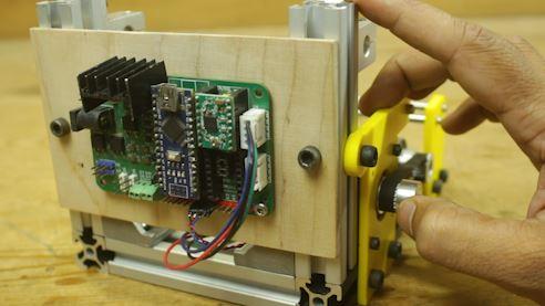
Step 1: Making Machine Frame Using 20x20 Profile
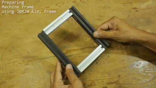


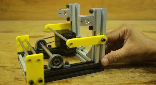
Creating a Label Sticker Dispenser Machine Frame:
Making the frame for a label sticker dispenser machine is like building the skeleton of a robot. This frame will hold everything together and make sure the machine works smoothly. We'll use some materials like a 20x20 aluminum frame, a Nema 17 stepper motor, an 8mm smooth rod, 8mm pillow bearings, and some 3D printed parts.
Step 1: Get Your Materials Ready
Gather all the materials you need. These include the aluminum frame, the Nema 17 stepper motor, the 8mm smooth rod, 8mm pillow bearings, and 3D printed parts. Make sure everything is clean and in good condition.
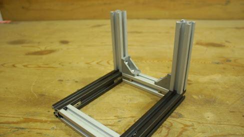
Step 2: Assemble the Base
Lay out the 20x20 aluminum frame pieces on a flat surface to create the base of the machine. Make sure they fit together properly. You might need to use screws or brackets to secure them in place. This base will provide stability for your machine.
Step 3: Attach the Stepper Motor
Now, fix the Nema 17 stepper motor to the frame. It's like attaching the heart of the machine. This motor will help the machine move the stickers.
Step 4: Install the Smooth Rods
Slide the 8mm smooth rod into the pillow bearings. These bearings will make sure the rods can turn smoothly. Attach these rod and bearing assemblies to the frame. Think of them as the machine's arms that will carry the stickers.
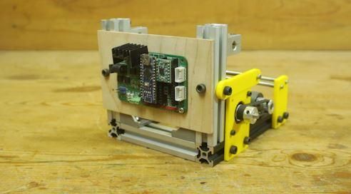
Step 5: Add 3D Printed Parts
You might have some 3D printed parts that are custom-made for your machine. Attach these parts to the frame as needed. They can be like the hands and fingers of the machine, helping with the sticker dispensing process.
Step 2: Electrical Wiring and Custom PCB


Wiring Connection Details for Arduino-based Label Sticker Dispenser Machine:
In the assembly of your label sticker dispenser machine, it's important to have clear and accurate wiring connections to ensure proper functionality. Here's a detailed write-up on how the wiring is set up for your project:
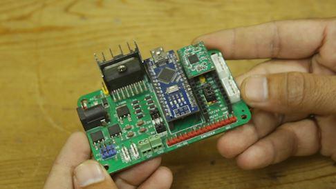
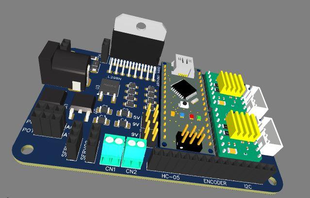
- Arduino Placement:
- The Arduino Nano is securely placed on a multipurpose PCB (Printed Circuit Board). This PCB acts as a central hub for connecting various components, allowing for organized and efficient wiring.
- Stepper Motor Control:
- The Nema 17 stepper motor is controlled by an A4988 stepper motor driver. The A4988 driver is set to operate the stepper motor in 16th steps mode, which provides precise and smooth motion control.
- Wiring the A4988 Driver to the Arduino:
- The step pin (for controlling the step movement) of the A4988 driver is connected to the A1 pin on the Arduino. This connection ensures that the Arduino can send step commands to the stepper motor through the driver.
- The direction pin (for controlling the rotation direction) of the A4988 driver is connected to the A0 pin on the Arduino. This connection allows the Arduino to determine the direction in which the stepper motor should rotate.
- Power Supply for Stepper Motor:
- The stepper motor is powered by a 12V DC power supply. This voltage level is suitable for the Nema 17 stepper motor's operation, providing the necessary power for its movements.
- IR Sensor Connection:
- An IR (Infrared) sensor is used in your project, and its output pin is connected to digital pin 4 on the Arduino. This connection enables the Arduino to receive signals from the IR sensor, which may be used for detecting objects or providing input based on proximity or presence.
By following these wiring connections, you ensure that your label sticker dispenser machine is set up to control the stepper motor accurately, receive input from the IR sensor, and run on the appropriate power supply. This organized and well-connected system is crucial for the successful operation of your project.
Step 3: CUSTOM PCB
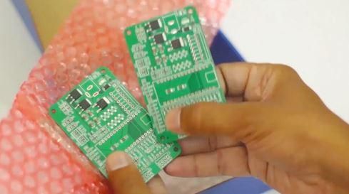


Unlock Innovation with JLCPCB - Your Ultimate PCB Solution
We're excited to introduce our latest project, made possible with JLCPCB's exceptional PCB service. We ordered our PCBs from JLCPCB, and the results have been outstanding.
One PCB, Infinite Possibilities
Our multipurpose PCB is a game-changer, designed to serve a multitude of projects. With JLCPCB's top-quality boards, you can now rely on a single PCB for a wide range of applications. Say goodbye to the hassle of designing new PCBs for every project.
Quality Meets Affordability
JLCPCB is our trusted partner because they offer the best in PCB quality without breaking the bank. The precision and reliability of their boards are unparalleled, making our projects run seamlessly every time.
Your Projects, Simplified
No matter your project - be it electronics, automation, or innovation - our multipurpose PCB, crafted with JLCPCB's expertise, will be your go-to solution. It's the smart choice for streamlining your work and reducing costs.
Experience Excellence with JLCPCB
Join the league of innovators who rely on JLCPCB for the best quality PCBs at incredibly affordable rates. Get ready to take your projects to new heights with JLCPCB as your trusted PCB partner.
so order the best quality PCB visit the link
JLCPCB 1-20 Layer PCB from $2, Sign up to Get $54 Coupons here: https://jlcpcb.com/?from=MrI
Step 4: Arduino Code
#include <Arduino.h>
#include "BasicStepperDriver.h"
// Motor steps per revolution. Most steppers are 200 steps or 1.8 degrees/step
#define MOTOR_STEPS 200
#define RPM 120
int flag = 0;
// Since microstepping is set externally, make sure this matches the selected mode
// If it doesn't, the motor will move at a different RPM than chosen
// 1=full step, 2=half step etc.
#define MICROSTEPS 16
// All the wires needed for full functionality
#define DIR A0
#define STEP A1
//Uncomment line to use enable/disable functionality
//#define SLEEP 13
// 2-wire basic config, microstepping is hardwired on the driver
BasicStepperDriver stepper(MOTOR_STEPS, DIR, STEP);
//Uncomment line to use enable/disable functionality
//BasicStepperDriver stepper(MOTOR_STEPS, DIR, STEP, SLEEP);
void setup() {
stepper.begin(RPM, MICROSTEPS);
// if using enable/disable on ENABLE pin (active LOW) instead of SLEEP uncomment next line
// stepper.setEnableActiveState(LOW);
pinMode(4,INPUT);
Serial.begin(9600);
}
void loop() {
if (flag == 1 && !digitalRead(4) ){
delay(1200);
flag = 0;
}
if (!digitalRead(4)){
stepper.stop();
flag = 1;
}
if (digitalRead(4)&& flag == 0){
stepper.rotate(1);
}
}
Here's a detailed explanation of the code:
#include <Arduino.h> #include "BasicStepperDriver.h"
The code includes the necessary libraries for Arduino and the "BasicStepperDriver" library for controlling the stepper motor.
#define MOTOR_STEPS 200 #define RPM 120 int flag = 0;
Here, constants are defined for the number of motor steps per revolution (200) and the desired revolutions per minute (RPM). The variable flag is also initialized to 0.
#define MICROSTEPS 16
This constant defines the number of microsteps per full step. In this case, it's set to 16, which means the motor will perform 16 microsteps for each full step, providing smoother and more precise motion.
#define DIR A0 #define STEP A1 //Uncomment line to use enable/disable functionality //#define SLEEP 13
Here, the digital pins used for controlling the stepper motor are defined. DIR is the direction pin (A0), and STEP is the step pin (A1). There is also a line of code that can be uncommented to define an additional pin for enabling/disabling the motor, but it is currently commented out in this code.
BasicStepperDriver stepper(MOTOR_STEPS, DIR, STEP);
An instance of the BasicStepperDriver class is created, specifying the number of motor steps, the direction pin, and the step pin. This class simplifies the control of the stepper motor.
void setup() { stepper.begin(RPM, MICROSTEPS); // if using enable/disable on ENABLE pin (active LOW) instead of SLEEP, uncomment the next line // stepper.setEnableActiveState(LOW); pinMode(4, INPUT); Serial.begin(9600); }
In the setup() function:
- The stepper instance is configured with the desired RPM and microstepping value.
- There's a conditional statement that sets the enable/disable functionality of the motor driver to active LOW if required, but it's currently commented out.
- Pin 4 is set as an input, which suggests it's used to read the state of an external sensor, possibly an IR sensor.
- Serial communication is initialized at a baud rate of 9600, which allows for communication with the Arduino IDE's Serial Monitor for debugging.
void loop() { if (flag == 1 && !digitalRead(4)) { delay(1200); flag = 0; } if (!digitalRead(4)) { stepper.stop(); flag = 1; } if (digitalRead(4) && flag == 0) { stepper.rotate(1); } }
In the loop() function:
- It checks the flag variable and the state of the digital pin 4 (IR sensor) to determine if the motor should start or stop.
- If the flag is set to 1 and the IR sensor is not active, it introduces a delay of 1200 milliseconds and resets the flag to 0, likely to prevent immediate reactivation.
- If the IR sensor is not active, it stops the stepper motor and sets the flag to 1.
- If the IR sensor is active and the flag is 0, it rotates the stepper motor by one step.
This code appears to control a stepper motor based on input from an IR sensor, stopping and starting the motor's rotation depending on the sensor's state and the flag variable.