 Scott Duckworth
November 1 update: IT WORKS!!!
It's a day late, but it works! I couldn't be happier!!!
Fixing that integer overflow bug did the trick!
I still need some tuning before I can call it reliable or smooth. But oh my gosh, it works!
Halloween night update
I had a hunch at 3pm today, quickly confirmed the hunch, and was able to quickly fix the central controller crash. It wasn't a crash at all, but rather getting stuck in an infinite loop when the radio received an unexpected packet (this is the 2.4GHz ISM band, so that packet could have come from anywhere). This was an easy fix, and after a few minutes of steady operation in the garage I decided to give it a shot.
I shifted into high gear and contacted my neighbors, asking if I could still use their roof. Amazingly, they both said yes (they are very patient with me!) but I didn't have a ladder tall enough to reach one of their rooftops, and not enough time to borrow the ladder from another friend, so I had to use the highest point on the neighborhood playground instead. I was literally running all over the street with a ladder, clamps, power cords, and motor assemblies. I was sweating bullets.
I hooked up the ghost to perform initialization. The moment of truth. Everything seemed to go smoothly with the procedure! Initialization finished and it told me the distance between houses was...negative?
In a scramble, I wasn't thinking clearly and just overrode the value to the absolute value that I was given. I tried moving the ghost to a point and the motors were fighting one another. The position numbers didn't make sense.
I did some last minute hacking and debugging on the controller. I rebooted it so many times, my phone decided it just wasn't gonna talk to the ESP32 on the network any more, so I was typing commands on my desktop and running outside to see if it worked.
Nothing. Made. Sense.
As trick-or-treaters started walking down the street, I let out a giant sigh. So close!
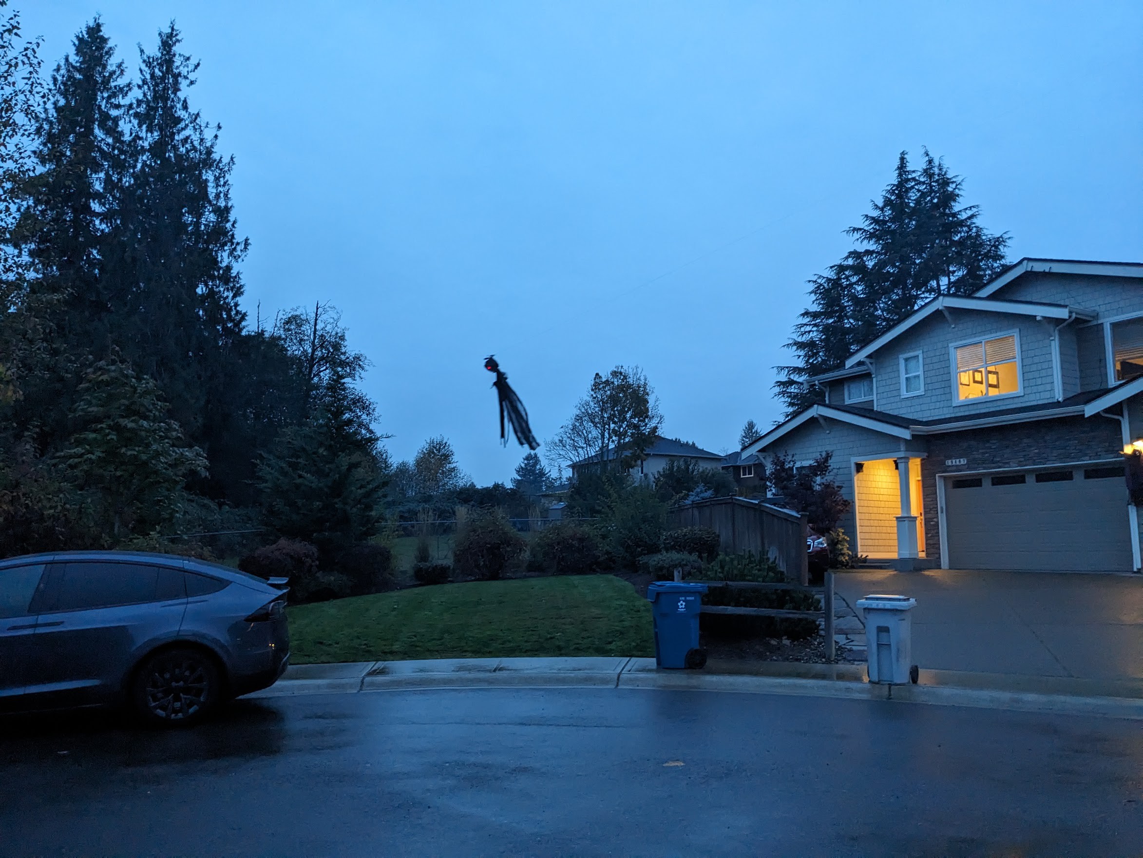
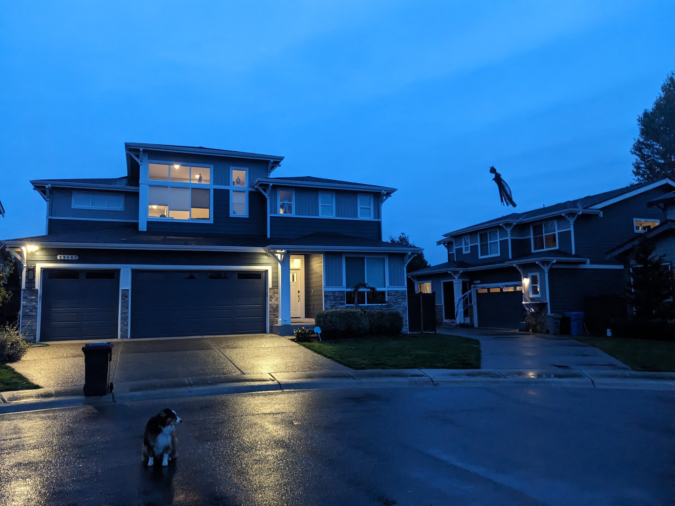
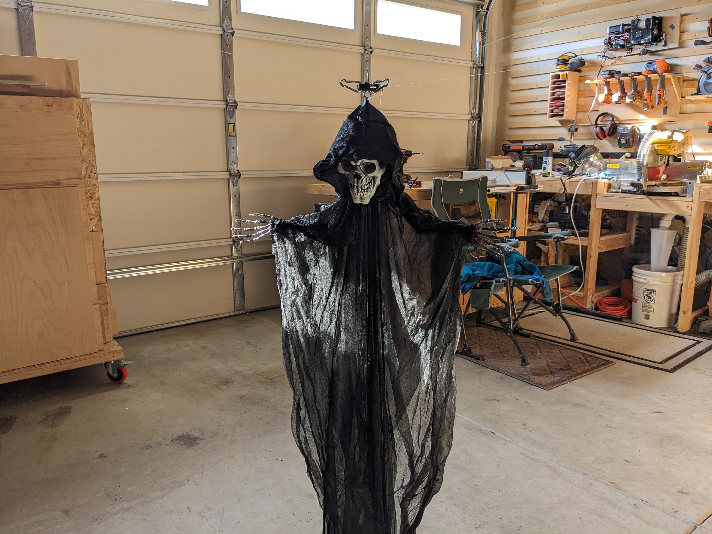
I left the ghost hanging in mid-air with its red eyes (flashing LEDs) turned on for a "normal" over-the-top Halloween decoration. Really, how many people string up a ghost from the rooftop of houses across the street?
Halloween night was still fun and chaotic. Lots of kids came, and we had friends over. Everyone enjoyed my Halloween props that I had made last year, including an automated coffin that opens with a skeleton that pops out and screams and sings, and some hidden spiders on stepper motors that drop from the ceiling of my porch. Some kids noticed and pointed at the ghost with flashing red eyes hanging way overhead.
But my mind was going a million miles an hour the whole time thinking what went wrong. I suspected integer overflow in the encoder counter, and snuck away from the chaos for a few seconds here or there to check various points in my code. Best I could tell, the encoder counter shouldn't overflow until it reached 214 meters, and the houses were much closer than that. Once the data was in the central controller, everything was in floating point, so an integer overflow wasn't possible there.
The chaos ended. Halloween was over. I sat down at my computer for 30 seconds of uninterrupted debugging and almost immediately found the bug.
int16_t sum = model.motor(motor_a_id).status.position + model.motor(motor_b_id).status.position;
float distance = sum * 1e-3f;
That int16_t should be int32_t, as that's what the position fields are. This number represents the distance in millimeters between motors, so anything over 32.767 meters would be problematic. This is effectively the first step after receiving a packet in the central controller, as it is being converted to floating point.
Being on the central controller, this would have been fixable.
I just needed 30 seconds more...
UGH!!!
Next year there will be a flying ghost on my street.
October 30 update
It's now October 30, the day before Halloween. I'm very happy with the progress that I've made on my project over the last few months. It "works", but I've decided that it's not quite ready for showtime. There's something about attaching these motors to my neighbors' houses and running it around little kids on Halloween night that tells me I shouldn't put it out this year.
I'll explain what I've done so far and how this thing works.
The Motor
Early on, I knew where I wanted to mount my control points - high points on my neighbors' rooftops, forming a triangle with sides ranging between 40-60 meters apart, about 8 meters above ground level. I need to keep the ghost elevated well above car level on the street, so I could only let the ghost drop about 2 meters below the mounting points.
A 2 meter rise over a 30 meter run forms a pretty small angle off of the horizontal, so I knew the lines would be under fairly high tension. Without any acceleration (aside from gravity), I calculated there would be roughly 8x more tension on the lines than the weight of the object hanging from the center point. I wanted to have a fairly high margin of error to account for wind, rain, acceleration, and other factors.
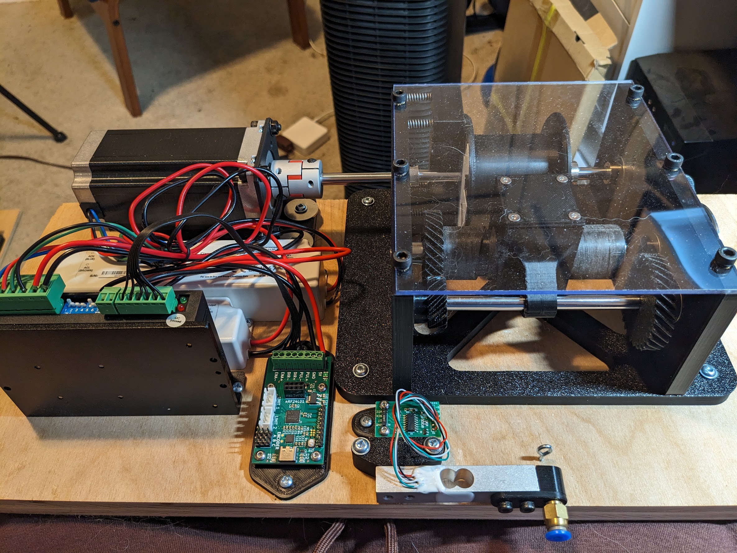
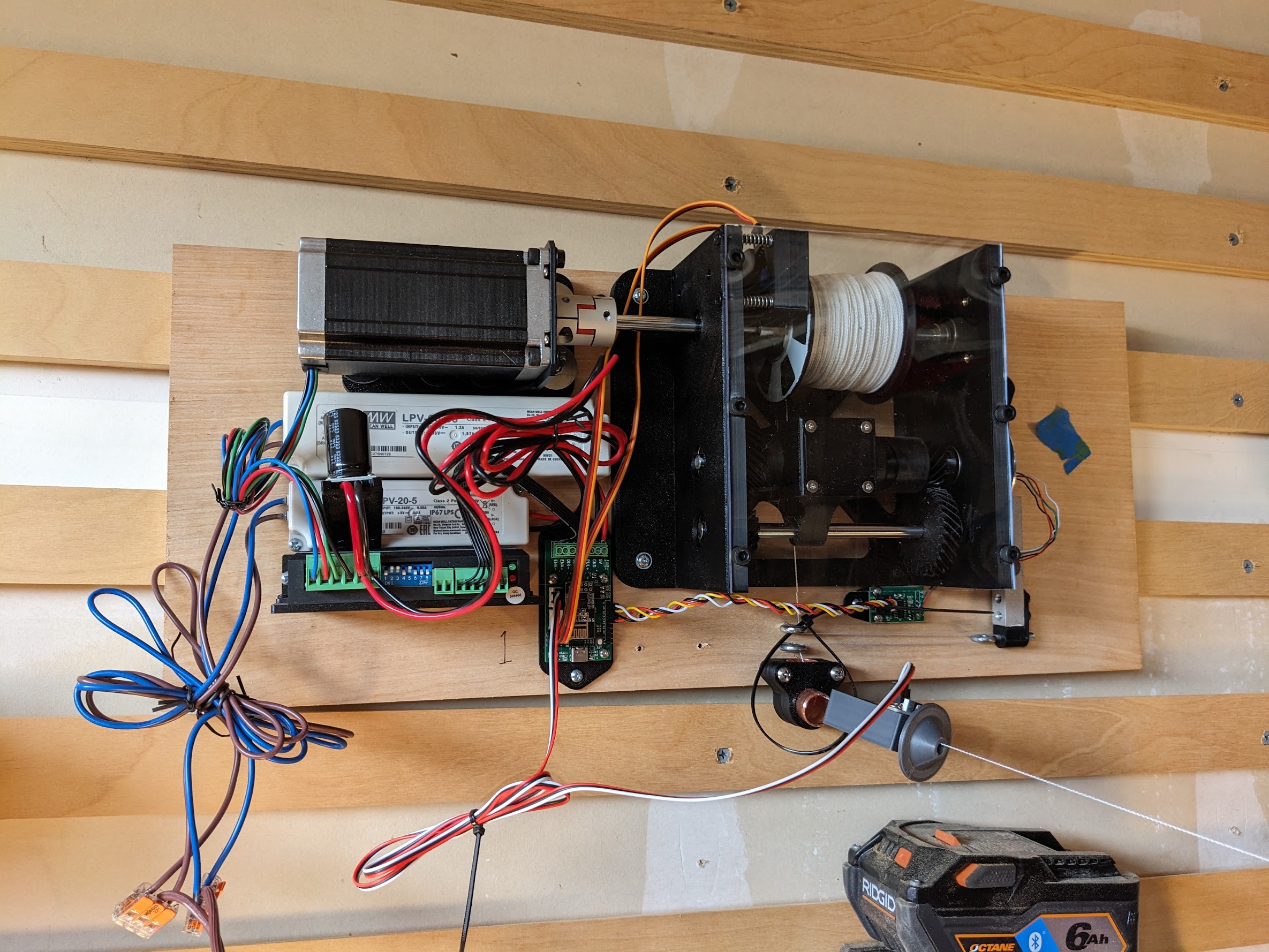
So I went with a beefy NEMA23 stepper motor capable of producing 3Nm of torque. I would drive this with a DM542T stepper motor controller fed by a 36V power supply. The stepper motor controller handles the high voltages and currents needed by the motor, but still needs step, direction, and enable inputs, each at 5V. For this, I'd need a motor controller.
The Encoder and Limit Switch
Stepper motors are capable of high precision positioning, but there's no position feedback. You only tell the motor to increment or decrement its position, but it can't tell you its current position. Additionally, the motor can slip under high load, or the motor could be disengaged, meaning that I would lose track of the length of line that was extended from the spool.
For this, I knew that I'd need an encoder and a limit switch. The limit switch detects when the line is fully retracted, and resets the position to zero. The encoder is a simple incremental quadrature encoder, which I made from two infrared reflective sensors and a 24 section pie pattern (hand cut with a hobby knife onto white duct tape using a 3D printed template) stuck on the side of the spool.
The Tension Sensor
As part of my homing process, I knew I'd need to detect when a line is under tension. I originally used a separate limit switch and a spring for this, but eventually incorporated a load cell. Using the load cell also enabled me to do things like disengage the motor when the tension is much higher than expected. I also disable extending the line when there is no tension, since this would just end up with a mess of fishing line as it loosens around the spool with nothing to pull it away.
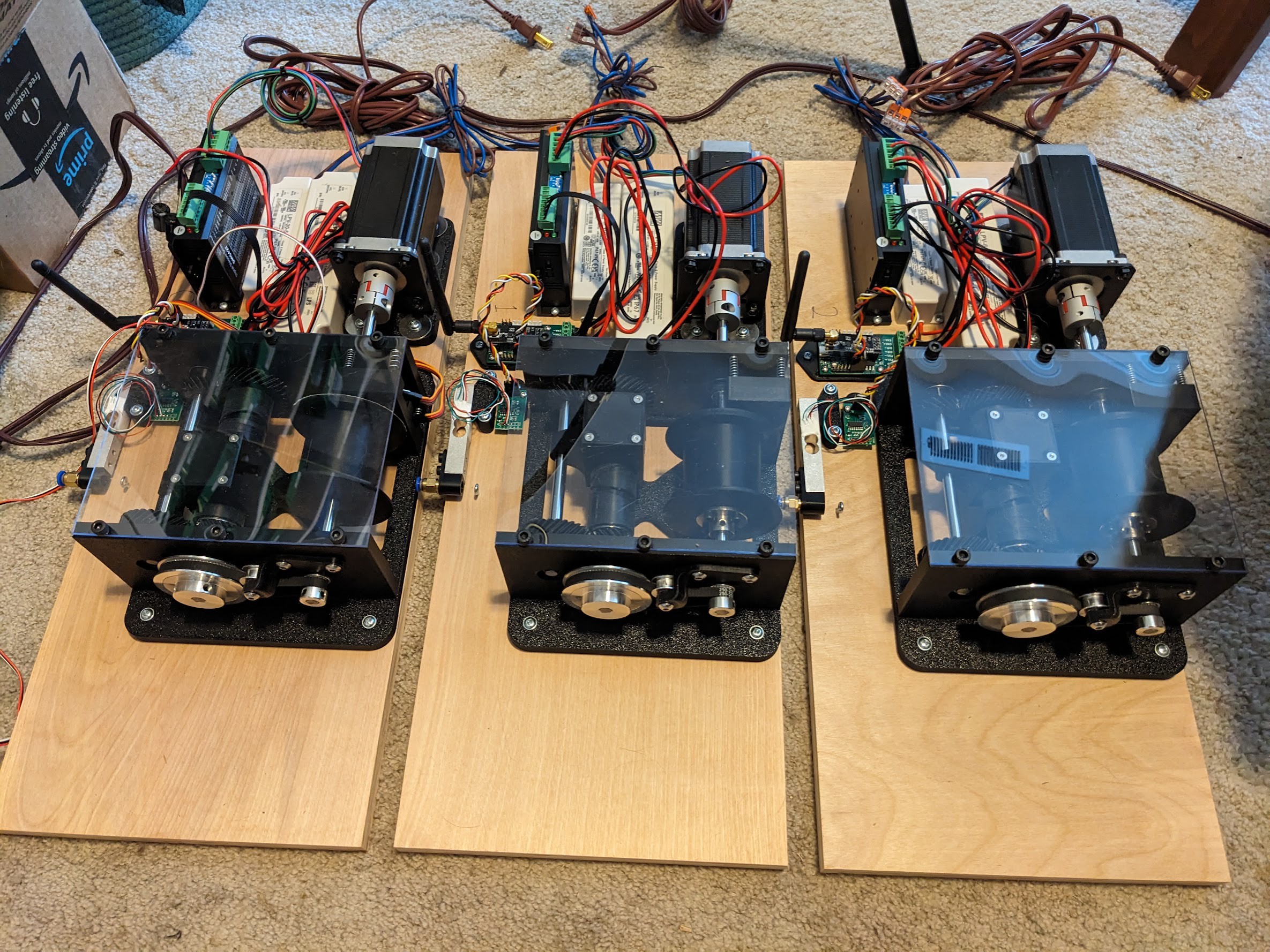
The Motor Controller Board
After a few design iterations of the motor controller, I ended up with a custom PCB based on a SAMD51. This CPU has way more horsepower than I needed, but I specifically wanted two hardware peripherals on the MCU: the timers and the PDEC (positional decoder).
I would use the timer to accurately control the step signals sent to the stepper motor driver. The last thing I wanted was for some software latency interfering with accurate timing of sending step signals, resulting in jittery performance (foreshadowing). All MCUs nowadays will have hardware timers, so most anything would have worked here, but I was familiar with the SAMD timer register interface.
The PDEC was harder to find on a MCU, and this is really what led me to the SAMD51 (the SAMD21 does not have a PDEC).
Did I really need a hardware PDEC? Maybe. At first I tried using software-based position decoder libraries, even libraries that leverage external interrupts, but the results I got were inconsistent. The software-based libraries would track at least 99% of the encoder steps, but it would occasionally miss steps. After running the ghost for a few minutes I'd find that it would wander off course, and I found that the encoder position was drifting over time. Switching to the hardware decoder on the SAMD51 completely eliminated this problem, as it samples the position pins at a whopping 48MHz, with nothing in software getting in the way of accurate readings.
Unfortunately the 48-pin SAMD51 overloads the PDEC pins with the USB D+/D- pins. While I don't strictly need USB or serial in the running system, it would be really convenient for debugging. So I added a CP2102 USB to serial interface on the board to talk through one of the hardware UARTs.
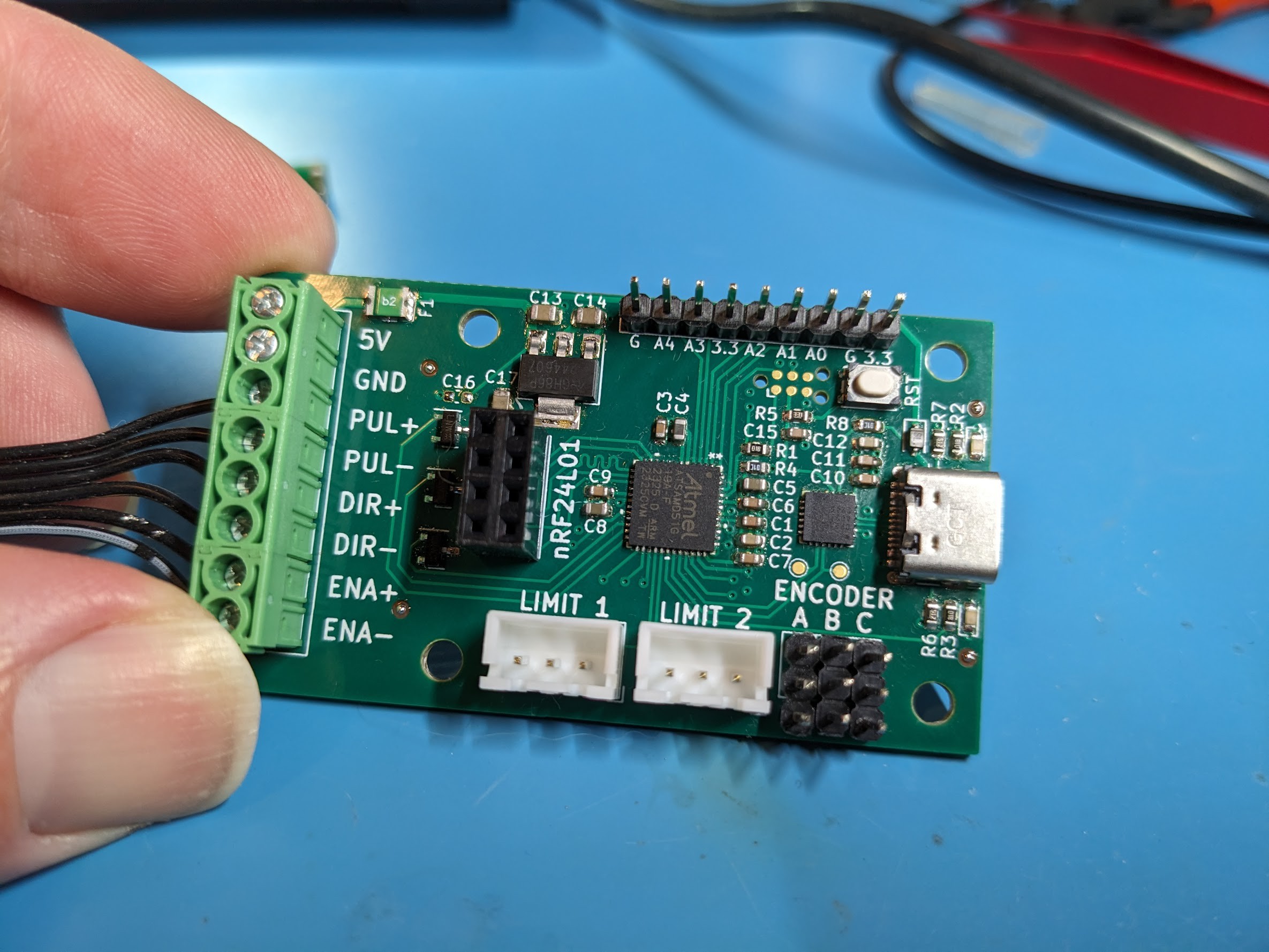
The motor controller board also holds the 3.3V linear regulator and some FETs used to translate the 3.3V step, direction, and enable signals from the MCU to the 5V signals needed by the stepper motor driver. I found that this was not strictly necessary, as the stepper motor driver inputs just drive an optocoupler, and 3.3V at the high driving current of the SAMD51 was sufficient. But it just felt wrong to drive signals to unknown hardware devices directly from the little MCU pins, so I added the FETs, which just sink the input voltage to ground.
The PCB is 4 layers, using mostly 0603 passive components with a few 0805 caps, all hand placed using stencil and solder paste, and soldered on a hot plate.
Some advice to my former self: when designing a custom board for a project like this, break out extra pins, even if you don't think you'll need it (assuming you're not space constrained). Custom PCBs are fairly inexpensive, so although a refab cycle isn't cost prohibitive, the 1-2 week delay can really dampen a project's velocity. Building in some flexibility to your board can really help keep a project moving when you find out you need an extra pin or two - even if you do refab the board, you can keep working in the meantime.
The Central Controller
It's an ESP32C3 on a little custom PCB to simplify attaching the wireless transmitter. There's nothing too special about this hardware; the interesting parts are in the software. It hosts a webpage, so that I can interact with the system, and it runs the motion control loop.
The controller keeps track of the last known linear position of each motor, the last velocity command that was sent, and an estimated linear position of each motor. Each motor periodically sends an absolute position update back to the central controller, which is handled simply by replacing the estimated position with the reported position. I had considered using a complementary filter or even a Kalman filter here, but I found that the hardware PDEC was so accurate that I'd prefer to always fully trust the position update.
The position estimation and control loop runs at 25Hz. I use a trilateration formula to convert the estimated linear position of each motor (how far the line is extended) into a 3 dimensional cartesian coordinate of the ghost's estimated position. This is fed into the motion control component, which calculates the desired next position, then triangulates that 3D position into a linear position for each of the motors' line extension, then sets a velocity on the motor so that the position is reached by the next control interval. It's complex stuff, but all pretty standard things for motion control systems.
For path planning, I implemented a few options: move to point, continually move in a circle, and move over a path defined by a Hermite spline (a smooth path defined by a series of control points and velocities).
Initialization Procedure
Much of the complexity of the central controller is in the initialization, or homing, routine. Upon startup, the motors and the central controller know nothing about their position. In order for the control mechanisms to work, the controller needs to know the absolute location of each motor's coordinates in 3D cartesian space as well as how far each motor is extended.
The homing routine zeroes out each motor (retract until the limit switch is triggered), then iteratively tensions (using the load cell to detect tension) all other motors and measures the distance between motors. It then takes the distances between pairs of motors and runs them through some trig functions to get the absolute position of each motor.
More precisely, for each pair of motors A and B, I perform the following steps:
1) Zero motor A
2) Disengage motor A
3) Zero motor B
4) Tension motor A
5) D(A, B) = the linear position of motor A
With 3 motors, this leaves me with 3 distances representing the lengths of 3 sides of a triangle.
I define the coordinate of motor 0 to be at (0, 0).
I define the coordinate of motor 1 to be straight out the X axis at (D(0, 1), 0)
The coordinate of motor 2 can be derived using the law of cosines and rotating the vector (D(0, 2), 0) by gamma. I assume that the motors are ordered in a counter-clockwise layout.
I can then apply an arbitrary translation and rotation offset to the resulting points so that the cartesian system is positioned how I like it.
This all assumes a 2 dimensional basis, and you could project this onto 3 dimensions by fabricating a Z value (e.g. assume 0). I have plans to capture the Z height of each motor using differential barometric pressure sensors - I have implemented this, but haven't tested it yet.
The Wireless Link
I experimented with a few wireless link layers: BLE, TCP, UDP (all using an ESP32, not the SAMD51), and Nordic's ESB protocol using the RF24L01+ module. I eventually settled on the latter.
BLE's range is seriously impressive. In an early test, I found that the signal could reliably reach about 4x longer than I needed for my application, even extending "through houses". What I didn't realize is that the cost of this reliability is latency. BLE will retry sending packets until it succeeds, and this may take a while. In my test setting (close range in a fairly noisy 2.4GHz suburban environment) I would often see latency around 50ms, but that often shot up to well over 300ms.
Given that I need to send updates to 3 motors at at least 5-10Hz, an update to a single motor taking 300ms was a complete show stopper for BLE.
I tried again using TCP over WiFi, and had very similar latency results as BLE. I tried UDP and the latency was very good, but the packet loss went through the roof - I was getting spikes of up to 60% packet loss over a few seconds.
At some point I decided that a small amount of packet loss wasn't a big deal, and I'd actually prefer that over latency, as long as I was sending control updates at a high rate. A missed velocity update here and there wouldn't make a big difference, right?
The RF24L01+ modules provided extremely low latency, and the protocol was flexible enough for me to implement both unicast and broadcast control protocols. In testing I was seeing very low packet loss.
The Mechanical Design
At first I just directly mounted the spool to the stepper motor, with a line guide centered on the spool. This resulted in the line "mounding up" on the spool, occasionally collapsing in on itself. I thought this wasn't a huge problem, but eventually found that when the line collapsed in on itself when under high tension, it would pinch the line as it dug into the mound of string. Then, when the motor extended the line, the line would be caught in the spool without enough tension on the line to pull it out, and it would end up winding the line in the opposite direction. The line would be retracting when the controller thought it was extending. Not good.
I knew I needed a way to cleanly wind the spool. I considered just using a deep sea fishing reel, but couldn't find a good way to put my position encoder on it. I tried a few alternative designs, but ended up designing a bi-directional lead screw.
The mechanical design was all done in Fusion 360. I 3D printed the majority of the parts, with the exception of the metal shafts, bearings, first stage drive pulleys, and polycarbonate top cover (which I cut on the table saw and drill press).
The deadline has arrived
On October 29, my personal deadline had arrived. I had encountered a number of challenges over the last few months, some related to this project and others just life interfering with my project time, which continually knocked me off schedule.
At 3am the night before my deadline day I was making some last minute changes on the cable routing mechanism, trying to avoid some high friction issues with the line. I swapped out the bicycle brake housing I was using for a simple copper elbow. I was seeing a lot of jittering, and hoped this would fix it.
The next morning I quickly setup an integration test environment in my garage - it's a bigger space than where I had previously been working. I knew there were some bugs still in the system, and I wanted to see how bad they would be at a bigger scale before I climbed 25 feet up a ladder to install these things on people's rooftops.
I continued to face problems in this last minute test. The radios that were working fine in my office were completely dropping out at this slightly longer range. I swapped out the little nRF24L01 modules for alternate ones from my pile of stuff, and found some that worked better. I only have cheap RF24 modules from Amazon that are probably all knock-offs, and are known for having a few bad ones in the pack of 5 that you get for $10 or whatever.
The jittering that I saw the night before, which I had attributed to high friction and thought I might have fixed, was still present. I attached my phone to one of the motor controllers via USB (I'm glad I put that CP2102 on there) and watched the stream of velocity updates which were being logged as the ghost was going in a circle. Most of the velocity updates looked reasonable, but I would occasionally see a velocity value that was drastically different than what I would have expected for a circular pattern.
I suspect what's happening is there's some packet loss in the velocity update packets that are broadcast, then the motor sends a position update to the central controller and it has to make a large velocity change to get back on course. This results in jittery behavior.
And then, of course, the central controller crashed, sending the motors spiraling off at whatever velocity they were last given. I haven't yet identified the source of the crash, and I'm suspicious that it may be a brownout caused by high current draw of the RF24L01 module (of course there's no way it could be my software that's crashing! <wink>). I should really redo that controller board so that I'm not entirely dependent on the 3.3V regulator on the little ESP32 board that's rated for an unknown amount of current (it's getting pretty warm).
What's next?
Halloween is tomorrow, and there's no way I'm fixing these problems and getting it all mounted by then. But I have high hopes for next year.
I already have a good idea of how to make movement much smoother, which almost entirely eliminates any dependence on a low latency wireless link. Essentially, I can buffer the next few seconds of the planned path to each of the motor controllers, keep time relatively synchronized between the motors, and let each motor independently execute its part. Instead of a nominal 25Hz update rate with intermittent gaps from packet loss, I could probably get a few hundred Hz update rate since it's all executed locally. The SAMD51's Cortex M4F CPU is mostly idle now, since the stepper motor timer and position decoder are all offloaded to hardware, so I could easily run more complex tasks on it, like spline path evaluation at a high frequency.
I'd still like to add in some kind of interaction with trick-or-treaters. Maybe use infrared cameras or PIR sensors to track them, and have the ghost circle overhead or something.
Conclusion (for now)
As you can probably tell from above, my primary goal for this project was to have an outlet for my creative engineering juices. Making a Halloween prop was really just a secondary goal. I definitely succeeded in my primary goal, but I haven't yet delivered on the secondary goal.
I'm happy that I worked through a lot of challenged and implemented the original control approach that I had in mind from the start. I experimented a lot, really improved my mechanical design and Fusion 360 skills, leveraged some PCB building skills that I've picked up over the last year, and tied together some fun concepts of state estimation, spline path evaluation, and motion control.
Most importantly, I had fun, and I expect I'll keep having fun with the idea. For a hobby project, I'll call this a success.