Subhajit
In this ESP32 tutorial, I have explained how to connect the TTP223 touch sensor with ESP32 to control relays. We will discuss what changes you must make in the circuit and source code to add to control relays with the TTP223 touch switch.

So after going through this article, you can add the TTP223 sensor to any of your home automation projects.

What is the TTP223 capacitive touch sensor?
The TTP223 is a compact capacitive touch sensor module that detects touch or proximity. It operates with low power consumption, making it suitable for battery-powered devices. When a conductive object, like a finger, approaches or touches the sensor pad, it provides a digital output signal (high or low) to indicate touch status.
During this article, I have covered the following topics:
- How to control relay with an inbuilt capacitive touch sensor of ESP32.
- Limitations for controlling multiple relays without TTP223 sensor.
- Control relays with TTP223 touch sensor. Explained the circuit and source code for connecting the TTP223 touch sensor.
Here I have used one of my previous Blynk projects. So with this home automation project, you can control the appliances with Blynk IoT, Bluetooth, IR, and touch switch.
So, you can easily make this touch-sensitive home automation project at home just by using an ESP32 and relay module or you can also use a custom-designed PCB for this project.
Required components:
- ESP32 DevKIT V1
- 4-channel 5V SPDT Relay Module
- TTP223 4-channel touch sensor
- TSOP1838 IR Receiver (with metallic case) Optional
- Any IR Remote
You can make this project just by using ESP32, an 1838 IR receiver, and a 4-channel relay module. But if you use PCB then you need the following components.
Required components for PCB:
- ESP32 DEVKIT V1
- DHT11 sensor
- 1838 IR receiver (with metallic case)
- Relays 5v (SPDT) (4 no)
- BC547 Transistors (4 no)
- PC817 Optocuplors (4 no)
- 510-ohm 0.25-watt Resistor (4 no) (R1 - R4)
- 1k 0.25-watt Resistors (6 no) (R5 - R10)
- 10k 0.25-watt Resistor (1 no) (R11)
- LED 5-mm (6 no)
- 1N4007 Diodes (4 no) (D1 - D4)
- Push Buttons (4 no)
- Terminal Connectors
- 5V DC supply
Inbuilt Capacitive Touch Sensor of ESP32
The ESP32 is a popular microcontroller module that comes equipped with various built-in features, including an inbuilt capacitive touch sensor. This capacitive touch sensor is a part of the ESP32's GPIO (General-Purpose Input/Output) pins, which can be configured to sense touch or proximity without the need for additional external components.
- Sensing Mechanism: The capacitive touch sensor on the ESP32 works by measuring changes in capacitance. When a conductive object (such as a human finger) approaches or touches a capacitive touch-enabled GPIO pin, it causes a change in the capacitance, which is detected by the ESP32.
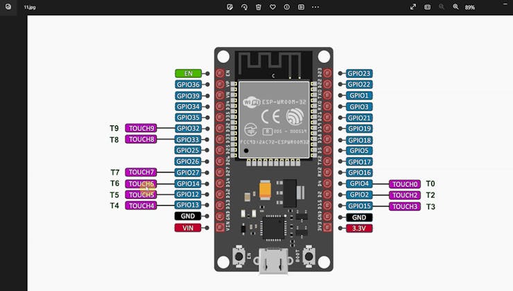
- Number of Touch Pins: Here we are using the DOIT ESP32 DevKIT V1 model, so it has a total of 10 GPIOs that can be used as the touch pin. (Please refer to the Pinout diagram on the top).
- Configuration: To use the capacitive touch sensor, you need to configure the GPIO pin as a touch input using the ESP32's software development environment, such as the Arduino IDE or ESP-IDF. You can set the sensitivity and other parameters for each touch-enabled pin.
ESP32's software libraries and development tools provide easy-to-use functions for configuring and reading the capacitive touch sensor values, simplifying the development process.
Control Relay Without External Touch Switch

Here I have used the inbuilt Capacitive Touch Sensor of ESP32.

If you want to control a single relay, then refer to the above circuit.
The GPIO D27 which T7 is used as the Touch pin.
And the relay is connected to the GPIO D13.
Please refer to the following code for the 1-channel relay.
Now if you want to control multiple relays then I will recommend you to use an external touch sensor like TTP223 with ESP32.
Circuit Diagram of the ESP32 TTP223 Project

The circuit is very simple, I have used the GPIO pins D23, D22, D21 & D19 to control the 4 relays.
The GPIO pins D13, D12, D14 & D27 are connected to the TTP223 touch sensor to control the 4 relays manually.

You can use either 4-channel or 4 1-channel TTP223 touch sensors as per the above circuits.
IR remote receiver (TSOP1838) connected with D35.
I have used a 5V mobile charger to supply the smart relay module.
Please take proper safety precautions while working with high voltage.
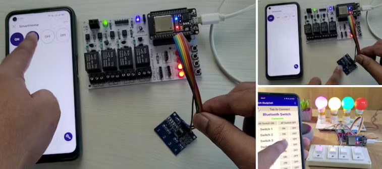
Control Relays With Blynk Bluetooth & Touch Switch

Now before designing the PCB, I have tested the circuit.
Here you can see, that you can control the relays with Blynk IoT, Bluetooth, IR remote, and TTP223 touch switch.
In the following steps, I will explain all the steps.
Design the PCB for ESP32 Smart Home System

To make the circuit compact and give it a professional look, I designed the PCB after testing all the features of the smart relay module.
You can download the PCB Gerber, BOM, and "pick and place" files of this ESP32 control relay PCB from the following link:
GitHub link to Download PCB Gerber File
For this project, you can also use the JLC SMT Service while ordering the PCB.

Why you should use JLC SMT Service?
On JLCPCB's one-stop online platform, customers enjoy low-cost & high-quality & fast SMT service at an $8.00 setup fee($0.0017 per joint).
$27 New User coupon & $24 SMT coupons every month.
Visit https://jlcpcb.com
JLCPCB SMT Parts Library 200k+ in-stock components (689 Basic components and 200k+ Extended components)
Parts Pre-Order service https://support.jlcpcb.com/article/164-what-is-jlcpcb-parts-pre-order-service
Build a Personal library Inventory, save parts for now or the future
Assembly will support 10M+ parts from Digikey, Mouser.
Steps to Order the PCB Assembly from JLCPCB
1. Visit https://jlcpcb.com and Sign in / Sign up.

2. Click on the QUOTE NOW button.

3. Click on the "Add your Gerber file" button. Then browse and select the Gerber file you have downloaded.

4. Set the required parameters like Quantity, PCB masking color, etc.

5. Select the Assemble side and SMT Quantity.

6. Now upload the BOM and PickAndPlace files.

7. Now confirm all the components which you want to be soldered by SMT services.

8. Click on the SAVE TO CART button.
Select Shipping Address and Payment Mode

6. Type the Shipping Address.
7. Select the Shipping Method suitable for you.
8. Submit the order and proceed with the payment.
You can also track your order from the JLCPCB

My PCBs took 3 days to get manufactured and arrived within a week using the DHL delivery option.
PCBs were well-packed and the quality was good at this affordable price.


Get the IR Codes (HEX Code) From the Remote

Now, to get the HEX codes from the remote, first, we have to connect the IR receiver output pin with GPIO D35.
And give the 5V across the VCC and GND. The IR receiver must have a metallic casing, otherwise, you may face issues.
GitHub link to Download code to get HEX code
Then follow the following steps to get the HEX codes
- Install the IRremote library in Arduino IDE
- Download the attached code, and upload it to ESP32.
- Open Serial Monitor with Baud rate 9600.
- Now, press the IR remote button.
- The respective HEX code will populate in the serial monitor.
Save all the HEX codes in a text file.
Configure the Blynk IoT Cloud

Click on the following link to create a Blynk Cloud account.
https://blynk.cloud/dashboard/register
- Enter your email ID, then click on "Sign Up".
- You will receive a verification email.
- Click on Create Password in the email, Then set the password, and click on Next.
- Enter your first name, and click on Done.
After that Blynk cloud dashboard will open.
Create a New Template in Blynk Cloud
First, you have to create a template in the Blynk cloud.
- Click on New Template.
- Enter a template name, select the hardware as ESP32, and the connection type will be WiFi.
- Then click on DONE.
You will get the BLYNK_TEMPLATE_ID and BLYNK_DEVICE_NAME after creating the temple.

After that, you have to create Datastreams. Here I will control 4 relays, so I have to create 4 Datastreams.
- Go to the Datastreams tab.
- Click on New Datastream and select Virtual Pin.
- Enter a name, select the virtual pin V1, and the datatype will be Integer.
- Then click on Create.
Similarly, create 4 datastreams with virtual pin V1 to V4. (Refer to Picture)
Set Up Blynk Cloud Web Dashboard

Now go to the Web Dashboard tab.
Drag and drop 4 Switch widgets.
Go to the settings of each widget, and select a Datastream.
Please refer to the tutorial video for more details.
Then click on Save to save the template.
Add Device Using Template in Blynk IoT
Steps to add a device in the Blynk IoT cloud:

- First, go to Device, then click on "New Device".

- Click on "From template".

- Select the Template, and give the device name.
- Click on Create.

Then in the device info tab, you will get the Blynk Auth Token, Template ID, and Device Name. All these details will be required in the code.
Program the ESP32 for This Blynk Project
GitHub link to Download the Main code

Download and install the following libraries in Arduino IDE
- Blynk Library (1.0.1): https://github.com/blynkkk/blynk-library
- AceButton Library (1.9.2): https://github.com/bxparks/AceButton
- IRremote Library (3.6.1): https://github.com/Arduino-IRremote/Arduino-IRremote
Now open the main sketch (code).
- In the code, you have to update the BLYNK_TEMPLATE_ID, BLYNK_DEVICE_NAME, Auth Token,
/* Fill-in your Template ID (only if using Blynk.Cloud) */
#define BLYNK_TEMPLATE_ID ""
#define BLYNK_TEMPLATE_NAME ""
#define BLYNK_AUTH_TOKEN ""
- update the WiFi Credentials.
// Set password to "" for open networks.
char ssid[] = "";
char pass[] = "";
- Then update the HEX codes of the IR remote as shown in the tutorial video.
//Update the HEX code of IR Remote buttons 0x<HEX CODE>
#define IR_Button_1   0x1FEE01F
#define IR_Button_2   0x1FE10EF
#define IR_Button_3   0x1FE906F
#define IR_Button_4   0x1FE50AF
#define IR_All_On     0x1FE807F
#define IR_All_Off    0x1FE48B7
After doing these changes, go to Tools and select the board as "ESP32 Dev Module", Partition Scheme as "Huge APP (3MB...)" and the proper PORT in Arduino IDE.

Then click on the upload button to program the ESP32 board.
While uploading the code to ESP32, if you use the PCB then you will see the "Connecting....___" text, then press and hold the BOOT button and then press the EN button, after that release both buttons.
Install Blynk IoT App to Configure Mobile Dashboard

- Install the Blynk IoT app from the Google Play Store or App Store. Then log in.
- Go to Developer Mode.
- Tap on the template that you have already made.
- Now go to the Widget box (on the right) to add widgets.
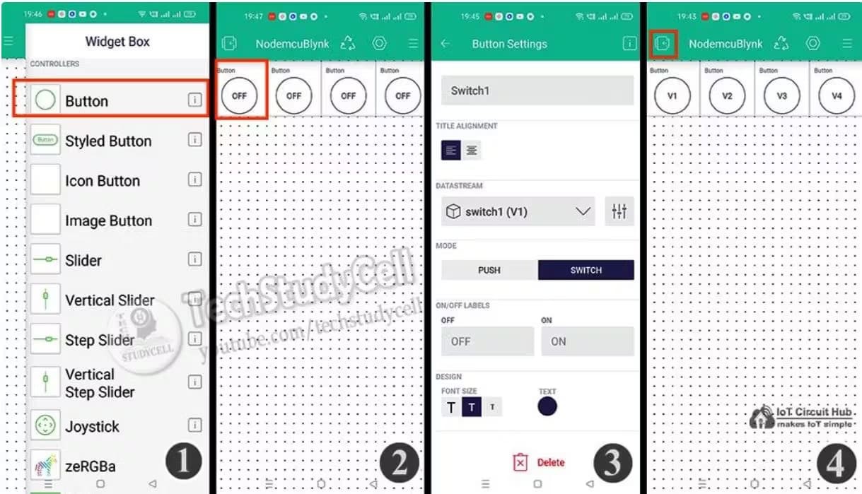
- Add 4 Button widgets from the Widget Box.
- Go to the Button widget settings.
- Enter the name, select Datastream, Mode will be Switch. Then exit.
- After setting all the Buttons tap on exit.
Download and Setup the Bluetooth App
If the ESP32 is not connected to WiFi, still you can control the relays from mobile using Bluetooth.
I have designed the Bluetooth Switch App in MIT App Inventor for this ESP32 Bluetooth project.
Please download and install the Bluetooth App (GitHub Link), then you have to connect the Bluetooth App with ESP32.