 Silícios Lab
The incorporation of the ESP8266 module into home automation represents a significant advancement in the field of smart home technology. The ESP8266, a microcontroller with built-in Wi-Fi connectivity, offers a powerful and affordable platform for creating highly customized home automation systems. With the ability to communicate with devices and sensors via a wireless network, the ESP8266 allows homeowners to remotely control a wide range of functionality in their home, such as lighting, temperature, security and more, transforming conventional homes into living spaces. efficient, secure and highly customizable.
Integrating the ESP8266 module with relays offers a highly versatile approach to creating home automation systems and controlling devices on the power grid via the internet.
The ESP8266, a microcontroller with built-in Wi-Fi connectivity, is a popular choice due to its ease of use, affordability, and active developer community. When combined with relays, which act as remotely controlled switches, this set allows users to control electrical devices, such as lamps, appliances and security systems, from anywhere in the world, through a simple internet connection. This not only adds a level of convenience to everyday life, but also contributes to the energy efficiency, security and personalization of home systems, making home automation an accessible reality for a wide audience.
In this article you will learn how to create a circuit capable of activating various devices in your home via the internet. Below we have an image of the electronic board that we will make available for you to transform your home into a smart home. Download now the project files
_RLeG8I5fL7.png?auto=compress%2Cformat&w=740&h=555&fit=max)
Let's get started and learn how each circuit block on this electronic board works.
Electronic Schematic of the ESP8266 Home Automation Board
The electronic circuit of the circuit board is made up of several blocks and below we have presented the electronic circuit of the circuit board is made up of several blocks and below we have presented the complete electronic schematic.
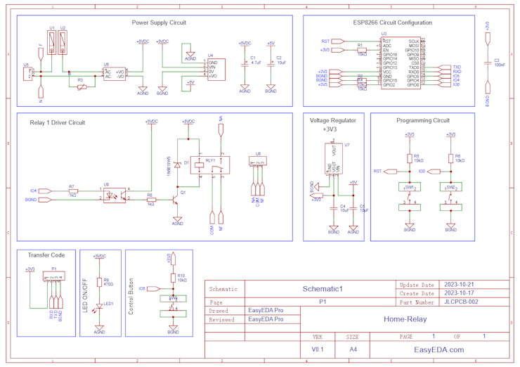
Next, we will explain the functionality of each circuit block.
Power Supply Circuit of ESP8266 Home Automation Board
The circuit below represents the power supply block of the electronic project. The first stage of the project consists of a screw connector that allows powering the circuit board directly from the 220VAC electrical network.
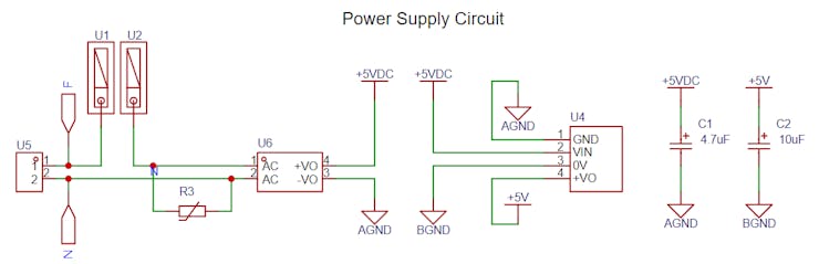
At the source input there is a circuit with fuse and varistor. Its purpose is to protect the circuit against overload or short circuit.
After that, this voltage passes through the HiLink AC-DC converter, which provides 5V at its output. Another element was used in this project, the isolated DC-DC converter B0505S. It was used with the aim of creating an isolated source to power the ESP8266 circuit and relay drive circuit using an optocoupler.
The objective is to create a source isolated from the main source and minimize possible interference from external noise in the ESP8266 circuit as much as possible.
As you can see, there are two 5V power supplies isolated from each other, each one has its own GND.
The +5V isolated voltage source is used at the input of the +3V3 voltage regulator circuit.
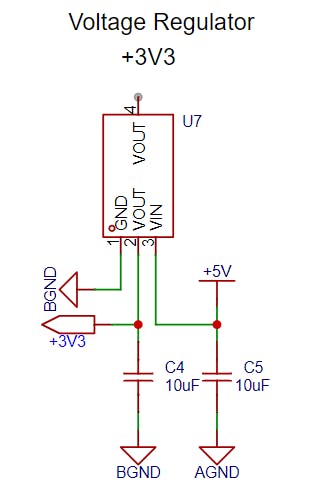
It is through this voltage regulator that the ESP8266 circuit is powered.
Electronic Circuit of the ESP8266
Below we have the basic operating circuit of the ESP8266. Upon connecting the ESP8266 to power and its basic components, the ESP8266 will execute its control firmware.
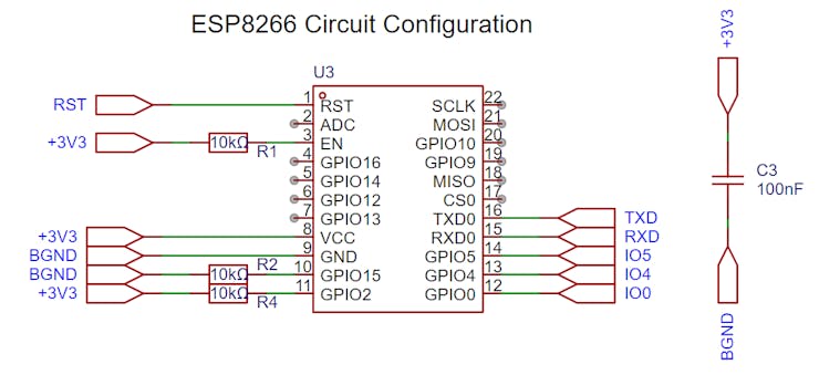
Associated with this circuit, we have the programming mode configuration block, which is made up of two buttons. These two buttons are responsible for putting the ESP8266 into programming mode.
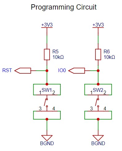
This way, you will be able to transfer code to your ESP8266. Code transfer is carried out through the pins of the circuit block below.
Your code will be stored in the ESP8266's memory and will be ready to control the relay to activate the load you desire.
After all, how does the relay activation circuit work?
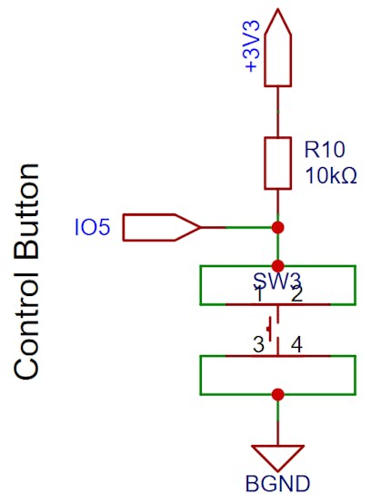
Relay Drive Circuit with ESP8266
The relay activation circuit with ESP8266 can be activated in 2 ways. The first is through the button below. It is a general purpose button and can be used in programming for manual activation or for any other task you want.
The other way to control the relay is through commands sent via a website. The command will be sent over the internet and will activate the relay. The electronic circuit of the relay is shown below.
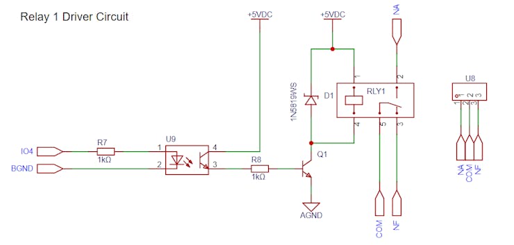
In the circuit above we have the relay being activated through an optocoupler, which guarantees the isolation of the activation signal. Furthermore, it is possible to observe that the two sides are completely isolated through two 5V voltage sources.
In other words, we have a voltage source to drive the optocoupler and another to drive the relay coil.
The relay has normally open and normally closed contacts to control the connected load.
From this circuit, the electronic design of the printed circuit board below was developed.

Using this electronic board, you can develop countless applications and connect your home to the internet.
Electronic Applications with ESP8266 Home Automation
Home automation with the ESP8266, driving relays to control devices over the internet, offers a diverse range of applications, making life more convenient and efficient. A classic example is lighting control. With the ESP8266 and relays, you can turn your home's light bulbs into smart devices that can be turned on, off, or programmed remotely.
This not only increases convenience, but also saves energy by allowing you to turn lights on or off in different rooms of your home, whether you're on the couch or on the other side of the world.
Additionally, the ESP8266 with relays can be used to automate blinds and curtains, allowing you to adjust the brightness and privacy of your home with a simple tap on your smartphone. If you are a gardening enthusiast, you can create a smart irrigation system that automatically adjusts the watering of your plants based on local weather conditions.
Additionally, controlling electrical appliances such as air conditioning and heaters allows you to optimize the comfort of your home, saving energy and money. These are just a few of the countless exciting applications that home automation with ESP8266 and relays offers, making your home smarter and more efficient than ever.
Next, you can have access to all printed circuit board files and receive free PCBWay units in your home.
ESP8266 Home Automation Electronic Board Project Files
PCBWay supported the creation of this project and made some units available for you to earn for free and receive 5 units at your home. To receive them, access this link, create an account on the website and receive coupons for you to win right now.
Download now the project files
Acknowledgments
We would like to thank PCBWAY for supporting the development of this project and availability in supplying electronic boards for the ESP8266 Home Automation project.