 agp.cooper
An Integer Version of the Demodulator
As the code will be ported to a lowly Arduino using C code, I first looked at if I could use 16 bit signed integers. The answer is strictly yes. Strictly in that the 32 bit result of a 16 bit multiplication is not used for the following division. For assembler you can take advantage of the 32 bit result of a multiplication and division, but "C" does not. This strict requirement limits the variable resolution to +127 and -128 as the high byte is used as intermediate overflow before a resoring division. In simple terms I am using fixed point arithmetic.
Code Optimisation
Note that the code only uses the high 8 bits of the ADC value even though the ADC is 10 bits.
The main drawback with using integer variables is the small signal range. The basic code can detect signals with peak to peak (pp) voltages between 380 mv pp and 5v pp. The correlation function amplitude is a square of signal amplitude.
The demodulator is insensitive to phase and gaussian noise. The demodulator is however very sensitive to harmonic distortion such as clipping and to a lesser extent to attempts to compress the input signal amplitude range (I did try).
The solution is to take the square root of the correlation. Then the correlation function amplitude is linear to the signal amplitude. This extends the detection signal range down to 78 mv pp (i.e. 2 bits).
Different low pass filters were tested with a four pole 900 Hz (-3 dB) determined to work the best.
For maximum dynamic signal range and considering some noise, a signal of 1 v pp should be targeted.
Here is the Excel code:
Option Explicit
Sub AFSKDem()
Application.ScreenUpdating = False
Application.Calculation = xlCalculationManual
Application.EnableEvents = False

Dim Fspace As Integer
Dim Fmark As Integer
Dim Fsample As Integer
Dim Baud As Integer
Dim Ticks As Integer

Dim I As Integer
Dim Xroot As Integer

Dim Time As Integer
Dim Code As Integer
Dim DataIn As Integer
Dim Phase As Integer
Dim Signal As Integer
Dim Correl As Integer
Dim DataOut As Integer

Dim X2 As Integer
Dim X1 As Integer
Dim X0 As Integer
Dim Y2 As Integer
Dim Y1 As Integer
Dim Y0 As Integer
Dim Z2 As Integer
Dim Z1 As Integer
Dim Z0 As Integer
Dim S0 As Integer
Dim S1 As Integer
Dim S2 As Integer
Dim S3 As Integer
Dim S4 As Integer
Dim S5 As Integer
Dim S6 As Integer
Dim iSin(65) As Integer

' AFSK parameters
Fspace = 1200
Fmark = 2200
Fsample = 13200
Baud = 1200
Ticks = Fsample / Fmark * Fsample / Fspace

' Title
ActiveSheet.Cells(1, 1).Value = "iBell 202"
ActiveSheet.Cells(2, 1).Value = "Baud"
ActiveSheet.Cells(3, 1).Value = "Fspace"
ActiveSheet.Cells(4, 1).Value = "Fmark"
ActiveSheet.Cells(5, 1).Value = "Fsample"
ActiveSheet.Cells(6, 1).Value = "Ticks"
ActiveSheet.Cells(7, 1).Value = "Delay"
ActiveSheet.Cells(1, 2).Value = "i900Hz"
ActiveSheet.Cells(2, 2).Value = Baud
ActiveSheet.Cells(3, 2).Value = Fspace
ActiveSheet.Cells(4, 2).Value = Fmark
ActiveSheet.Cells(5, 2).Value = Fsample
ActiveSheet.Cells(6, 2).Value = Ticks
ActiveSheet.Cells(7, 2).Value = 6

' Integer Sin() table
iSin(0) = 127: iSin(11) = 237: iSin(22) = 237: iSin(33) = 127: iSin(44) = 17: iSin(55) = 17
iSin(1) = 139: iSin(12) = 243: iSin(23) = 231: iSin(34) = 115: iSin(45) = 11: iSin(56) = 23
iSin(2) = 151: iSin(13) = 247: iSin(24) = 223: iSin(35) = 103: iSin(46) = 7: iSin(57) = 31
iSin(3) = 163: iSin(14) = 251: iSin(25) = 215: iSin(36) = 91: iSin(47) = 3: iSin(58) = 39
iSin(4) = 174: iSin(15) = 253: iSin(26) = 206: iSin(37) = 80: iSin(48) = 1: iSin(59) = 48
iSin(5) = 185: iSin(16) = 254: iSin(27) = 196: iSin(38) = 69: iSin(49) = 0: iSin(60) = 58
iSin(6) = 196: iSin(17) = 254: iSin(28) = 185: iSin(39) = 58: iSin(50) = 0: iSin(61) = 69
iSin(7) = 206: iSin(18) = 253: iSin(29) = 174: iSin(40) = 48: iSin(51) = 1: iSin(62) = 80
iSin(8) = 215: iSin(19) = 251: iSin(30) = 163: iSin(41) = 39: iSin(52) = 3: iSin(63) = 91
iSin(9) = 223: iSin(20) = 247: iSin(31) = 151: iSin(42) = 31: iSin(53) = 7: iSin(64) = 103
iSin(10) = 231: iSin(21) = 243: iSin(32) = 139: iSin(43) = 23: iSin(54) = 11: iSin(65) = 115

' Generate some data to encode
Time = 0
Phase = 0
Signal = 0
Correl = 0
DataOut = 0
' Shift registers
S0 = 0
S1 = 0
S2 = 0
S3 = 0
S4 = 0
S5 = 0
S6 = 0
X0 = 0
X1 = 0
X2 = 0
Y0 = 0
Y1 = 0
Y2 = 0
Z0 = 0
Z1 = 0
Z2 = 0
For Code = 0 To 9
  ' DataIn = Int(Rnd + 0.5)
  ' DataIn = Code Mod 2
  If (Code = 0) Then DataIn = 0
  If (Code = 1) Then DataIn = 1
  If (Code = 2) Then DataIn = 0
  If (Code = 3) Then DataIn = 1
  If (Code = 4) Then DataIn = 1
  If (Code = 5) Then DataIn = 0
  If (Code = 6) Then DataIn = 0
  If (Code = 7) Then DataIn = 1
  If (Code = 8) Then DataIn = 1
  If (Code = 9) Then DataIn = 0

  ' Encode
  For I = 1 To Fsample / Baud

    If (DataIn = 0) Then
      ' Fspace
      Signal = iSin(Phase)-128
      Phase = Phase + Fsample / Fmark
      If (Phase >= Ticks) Then Phase = Phase - Ticks
    Else
      ' Fmark
      Signal = iSin(Phase)-128
      Phase = Phase + Fsample / Fspace
      If (Phase >= Ticks) Then Phase = Phase - Ticks
    End If

    ' Decode the data
    Z2 = Z1
    Z1 = Z0
    Y2 = Y1
    Y1 = Y0
    X2 = X1
    X1 = X0
    S6 = S5
    S5 = S4
    S4 = S3
    S3 = S2
    S2 = S1
    S1 = S0
    S0 = Signal
    X0 = S0 * S6
    ' Integer square root
    If (X0 > 1) Then
      Xroot = 17 + X0 / 130
      Xroot = (Xroot + X0 / Xroot) / 2
      Xroot = (Xroot + X0 / Xroot) / 2
      Xroot = (Xroot + X0 / Xroot) / 2
      X0 = Xroot
    ElseIf (X0 < -1) Then
      Xroot = 17 - X0 / 130
      Xroot = (Xroot - X0 / Xroot) / 2
      Xroot = (Xroot - X0 / Xroot) / 2
      Xroot = (Xroot - X0 / Xroot) / 2
      X0 = -Xroot
    End If

    ' 600 Hz (-3dB) four pole critically damped low pass filter using approximate fractions
    ' Y0 = X0 * 40 / 573 + X1 * 80 / 573 + X2 * 40 / 589 + Y1 * 83 / 88 - Y2 * 2 / 9
    ' Z0 = Y0 * 40 / 573 + Y1 * 80 / 573 + Y2 * 40 / 589 + Z1 * 83 / 88 - Z2 * 2 / 9

    ' 800 Hz (-3dB) four pole critically damped low pass filter using approximate fractions
    ' Y0 = X0 * 91 / 830 + X1 * 91 / 415 + X2 * 91 / 830 + Y1 * 127 / 188 - Y2 * 81 / 710
    ' Z0 = Y0 * 91 / 830 + Y1 * 91 / 415 + Y2 * 91 / 830 + Z1 * 127 / 188 - Z2 * 81 / 710

    ' 900 Hz (-3dB) four pole critically damped low pass filter using approximate fractions
    Y0 = X0 * 51 / 388 + X1 * 51 / 194 + X2 * 51 / 388 + Y1 * 11 / 20 - Y2 * 43 / 569
    Z0 = Y0 * 51 / 388 + Y1 * 51 / 194 + Y2 * 51 / 388 + Z1 * 11 / 20 - Z2 * 43 / 569

    ' 1000 Hz (-3dB) four pole critically damped low pass filter using approximate fractions
    ' Y0 = X0 * 59 / 382 + X1 * 59 / 191 + X2 * 59 / 382 + Y1 * 107 / 250 - Y2 * 49 / 1070
    ' Z0 = Y0 * 59 / 382 + Y1 * 59 / 191 + Y2 * 59 / 382 + Z1 * 107 / 250 - Z2 * 49 / 1070

    Correl = Z0
    If (Correl > 0) Then
      DataOut = 1
    Else
      DataOut = 0
    End If

    ActiveSheet.Cells(10, 1).Value = "Time"
    ActiveSheet.Cells(10, 2).Value = "DataIn"
    ActiveSheet.Cells(10, 3).Value = "Signal"
    ActiveSheet.Cells(10, 4).Value = "Correlation"
    ActiveSheet.Cells(10, 5).Value = "DataOut"
    ActiveSheet.Cells(11 + Time, 1).Value = Time
    ActiveSheet.Cells(11 + Time, 2).Value = DataIn
    ActiveSheet.Cells(11 + Time, 3).Value = Signal / 128#
    ActiveSheet.Cells(11 + Time, 4).Value = Correl / 128#
    ActiveSheet.Cells(11 + Time, 5).Value = DataOut - 3

    Time = Time + 1
  Next I
Next Code

Application.ScreenUpdating = True
Application.Calculation = xlCalculationAutomatic
Application.EnableEvents = True
End Sub
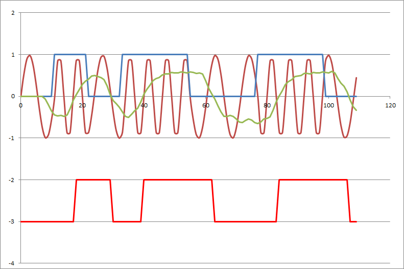
And here is the results:
Arduino Code
Analog Input Conversion Time
The ADC conversion (i.e. analogRead()) needs to speed up from 112 us (104 us theoretic minimum conversion time). This can be done (at the cost of reduced accuracy) by increasing the clock from 125 kHz to 1 MHz. The conversion time is now 17.2 us and the accuracy is still at least 8 bits.
The code to do this is:
// Define various ADC prescaler
const unsigned char PS_16=(1<<ADPS2);
const unsigned char PS_32=(1<<ADPS2)|(1<<ADPS0);
const unsigned char PS_64=(1<<ADPS2)|(1<<ADPS1);
const unsigned char PS_128=(1<<ADPS2)|(1<<ADPS1)|(1<<ADPS0);

  // Set ADC prescaler
  ADCSRA&=~PS_128;    // Remove bits set by Arduino library
  // ADCSRA|=PS_64;   // 64 prescaler (250 kHz assuming a 16MHz clock)
  // ADCSRA|=PS_32;   // 32 prescaler (500 kHz assuming a 16MHz clock)
  ADCSRA|=PS_16;      // 16 prescaler (1 MHz assuming a 16MHz clock)
Generating High Quality Audio
To do this we need two timers, one to generate the sample ticks at 13200 Hz and one to generate a fast PWM. Here is some code that I spent most of the day working on:
// Bell 202 modem
#define Fspace     1200
#define Fmark      2200
#define Fsample   13200
#define Baud       1200
#define sampleTicks  66     // sampleTicks = Fsample / Fmark * Fsample / Fspace
#define baudTicks    44     // baudTicks = Fsample / Baud

// Sine table for Fsample equal to 13200 Hz
#include <avr/pgmspace.h>
const byte iSin[sampleTicks] PROGMEM = {
  128,140,152,164,175,186,197,207,216,224,232,
  238,244,248,252,254,255,255,254,252,248,244,
  238,232,224,216,207,197,186,175,164,152,140,
  128,116,104, 92, 81, 70, 59, 49, 40, 32, 24,
   18, 12,  8,  4,  2,  1,  1,  2,  4,  8, 12,
   18, 24, 32, 40, 49, 59, 70, 81, 92,104,116,
};

// Define various ADC prescaler
const unsigned char PS_16=(1<<ADPS2);
const unsigned char PS_32=(1<<ADPS2)|(1<<ADPS0);
const unsigned char PS_64=(1<<ADPS2)|(1<<ADPS1);
const unsigned char PS_128=(1<<ADPS2)|(1<<ADPS1)|(1<<ADPS0);

void setup() {
  // Set ADC prescaler (assume a 16 MHz clock)
  ADCSRA&=~PS_128;                                 // Remove bits set by Arduino library
  // ADCSRA|=PS_64;                                // 64 prescaler (250 kHz)
  // ADCSRA|=PS_32;                                // 32 prescaler (500 kHz)
  ADCSRA|=PS_16;                                   // 16 prescaler (1 MHz)
  // About 17.2 us to return an ADC value but only good to 8 bits

  cli();                                           // Disable interrupts
  // ATmega48A/PA/88A/PA/168A/PA/328/P
  // Use Timer 0 for sample rate (13.2 kHz)
  // Note delay() and millis() will no longer work (use microseconds() instead)
  TIMSK0 = 0;                                      // Timer interrupts OFF
  TCCR0A = (2 << WGM00);                           // CTC mode
  TCCR0B = (2 << CS00);                            // prescaler 8, 2 MHz clock
  TIMSK0 = (1 << OCIE0A);                          // COMPA interrupt
  OCR0A = 151;                                     // Sample rate: 2 MHz/152 = 13.2 kHz

  // Use Timer 2 for Audio PWM
  // ATmega48A/PA/88A/PA/168A/PA/328/P
  // Note tone library will no longer work
  TIMSK2 = 0;                                      // Timer interrupts OFF
  TCCR2A = (2 << COM2A0)|(3 << WGM20);             // Fast PWM mode, toggle output on OC2A (PB3/D11)
  TCCR2B = (0 << WGM22)|(1 << CS20);               // 16 MHz clock
  OCR2A = 128;                                     // Duty cycle set in OCR2A  (128 = 0v)
  sei();                                           // Enable interrupts

  pinMode(11,OUTPUT);                              // Fast PWM
  pinMode(LED_BUILTIN,OUTPUT);
}


volatile byte Phase=0;
volatile byte Timer=0;
volatile byte DataPtr=0;
ISR(TIMER0_COMPA_vect) {
  OCR2A = pgm_read_byte(&(iSin[Phase]));
  Phase+=6;
  if (Phase>=sampleTicks) Phase-=sampleTicks;
  Timer++;
  if (Timer>=baudTicks) {
    Timer=0;
    DataPtr++;
  }
}

void loop() {

}
Currently the code generates a nice steady sine wave. Next is to add the data stream.
The PWM Filter
I had a play with a 3rd order Sallen Key:
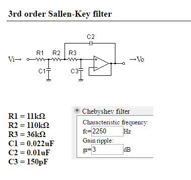
This particular filter is -3 dB down on both the Mark and Space frequencies and -80dB down on the 31.25kHz PWM frequency. I will need to use an OpAmp on the input side anyway so a single supply LM324 should work okay.
I thought about using a transistor for the OpAmp but the gain is insufficient except to act as a buffer for three sequential RC low pass filters (no fancy Chebyshev filters here!).
Demodulator Frequency Response
Before moving on I checked the input frequency response by hacking the code. Although not a proper analysis the results appear realistic:
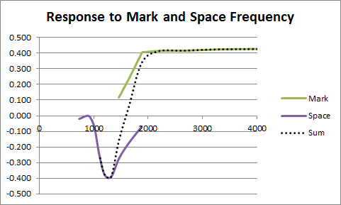
So the Space frequency response is pretty sharp (bandwidth about 550 Hz). The demodulator is insensitive to the bandwidth below about 1000 Hz which is probably why the Bell 202 protocol can use 150 baud and 387/487 Hz FSK as the return communications channel.
The Mark frequency response is open above 2200 Hz. A 2400 Hz low pass filter (in software?) may be of merit if high frequency noise may be present.
Demondulator Simplification
Could it really be simplified even more? Well yes, thinking about the radio mixer analogy I realised I could achieve a similar to the square and square root just by using the sign of the delayed signal (basically a switching mixer) . Here is the demodulator code:
    ' Decode the data
    S6 = S5
    S5 = S4
    S4 = S3
    S3 = S2
    S2 = S1
    S1 = S0
    S0 = Signal
    Z2 = Z1
    Z1 = Z0
    Y2 = Y1
    Y1 = Y0
    X2 = X1
    X1 = X0
    X0 = 0
    If (S6 > 0) Then X0 = S0
    If (S6 < 0) Then X0 = -S0

    ' 900 Hz (-3dB) four pole critically damped low pass filter using approximate fractions
    Y0 = X0 * 51 / 388 + X1 * 51 / 194 + X2 * 51 / 388 + Y1 * 11 / 20 - Y2 * 43 / 569
    Z0 = Y0 * 51 / 388 + Y1 * 51 / 194 + Y2 * 51 / 388 + Z1 * 11 / 20 - Z2 * 43 / 569

    DataOut = 0
    If (Z0 > 0) Then DataOut = 1
Yes, the four pole filter is the most complicated bit.
Now the benefit of this code is that the full ADC precision (10 bits) can be used without integer overflow.
Here is the results (including some corrections to the low pass filter):

---
Need More Speed
Even with my speed ups the interrupt service request (ISR) time estimate was 75 us. At 13200 Hz the total available time is 75 us, so I need to do better. The low pass filter cost about 25 us per stage so I dropped it back to one stage and lowered the cut off frequency. An few hour later I managed to get the Nano to generate a test pattern, feed it through an external two stage RC filter and then back again for decoding. Success, here is the screen shot:
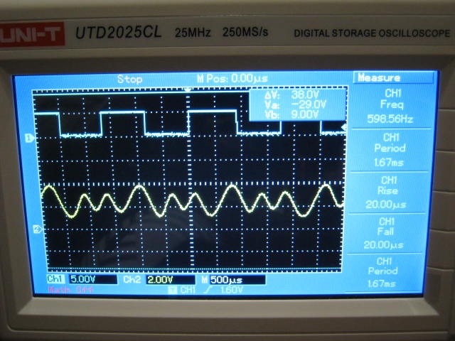
There is about a 50 us second delay between the input signal (yellow) and the digital output (blue). The input signal mark frequency is attenuated due to the simple two stage RC filter.
I am pretty pleased with this!
Here is the Arduino code:
// Bell 202 modem
#define Fspace     1200
#define Fmark      2200
#define Fsample   13200
#define Baud       1200
#define sampleTicks  66     // sampleTicks = Fsample / Fmark * Fsample / Fspace

// Sine table for Fsample equal to 13200 Hz
const byte iSin[sampleTicks] = {
  128,140,152,164,175,186,197,207,216,224,232,
  238,244,248,252,254,255,255,254,252,248,244,
  238,232,224,216,207,197,186,175,164,152,140,
  128,116,104, 92, 81, 70, 59, 49, 40, 32, 24,
   18, 12,  8,  4,  2,  1,  1,  2,  4,  8, 12,
   18, 24, 32, 40, 49, 59, 70, 81, 92,104,116,
};

// Define various ADC prescaler
const byte PS_16=(1<<ADPS2);
const byte PS_32=(1<<ADPS2)|(1<<ADPS0);
const byte PS_64=(1<<ADPS2)|(1<<ADPS1);
const byte PS_128=(1<<ADPS2)|(1<<ADPS1)|(1<<ADPS0);

void setup() {
  pinMode(11,OUTPUT);                              // Fast PWM
  pinMode(12,OUTPUT);                              // DataOut
  pinMode(A0,INPUT);                               // DataIn
  pinMode(LED_BUILTIN,OUTPUT);                     // Test loop speed

  // Set ADC prescaler (assume a 16 MHz clock)
  ADCSRA&=~PS_128;                                 // Remove bits set by Arduino library
  ADCSRA|=PS_16;                                   // 16 prescaler (1 MHz)
  // About 17.2 us to return an ADC value but only good for 8 bits

  cli();                                           // Disable interrupts
  // ATmega48A/PA/88A/PA/168A/PA/328/P
  // Use Timer 0 for sample rate (13.2 kHz)
  // Note delay() and millis() will no longer work (use microseconds() instead)
  TIMSK0 = 0;                                      // Timer interrupts OFF
  TCCR0A = (2 << WGM00);                           // CTC mode
  TCCR0B = (2 << CS00);                            // prescaler 8, 2 MHz clock
  TIMSK0 = (1 << OCIE0A);                          // COMPA interrupt
  OCR0A = 151;                                     // Sample rate: 2 MHz/152 = 13.2 kHz

  // Use Timer 2 for Audio PWM
  // ATmega48A/PA/88A/PA/168A/PA/328/P
  TIMSK2 = 0;                                      // Timer interrupts OFF
  TCCR2A = (2 << COM2A0)|(3 << WGM20);             // Fast PWM mode, toggle output on OC2A (PB3/D11)
  TCCR2B = (0 << WGM22)|(1 << CS20);               // 16 MHz clock
  OCR2A = 128;                                     // Duty cycle set in OCR2A  (128 = 0v)
  sei();                                           // Enable interrupts
}


volatile byte DataIn=0;
volatile byte DataOut=0;
volatile byte baudTick=11;
ISR(TIMER0_COMPA_vect) {
  static byte Phase=0;
  static int S0=0,S1=0,S2=0,S3=0,S4=0,S5=0,S6=0;
  static int X0=0,X1=0,X2=0;
  static int Y0=0,Y1=0,Y2=0;

  // Timer 2 controls PWM output
  OCR2A = iSin[Phase];
  if (DataIn==0) {
    Phase+=6;
  } else {
    Phase+=11;
  }
  if (Phase>=sampleTicks) Phase-=sampleTicks;
  // Done when baudTicks==0
  if (baudTick>0) baudTick--;

  // Decode the data
  S6=S5;S5=S4;S4=S3;S3=S2;S2=S1;S1=S0;
  X2=X1;X1=X0;
  Y2=Y1;Y1=Y0;
  S0=analogRead(A0)-512;                  // 18 us
  X0=(S6>0)?S0:-S0;
  // 600 Hz low pass filter
  Y0=(2*(X0+X1+X1+X2)+Y1*74-Y2*23)/59;    // 23 us
  DataOut=(Y0>0)?1:0;
}

void loop() {
  static byte lastBaudTick=0;
  static byte temp=0;

  if (lastBaudTick!=baudTick) {
    digitalWrite(12,DataOut);
    if (baudTick==0) {
      baudTick=11;
      DataIn=temp;
    } else if (baudTick==1) {
      temp=1-temp;
    }
    lastBaudTick=baudTick;
    // Output loop toggle: should be almost 6600 Hz and steady
    digitalWrite(13,!digitalRead(13));
  }
}
It should not worry the low pass filter too much if I replace it with:- Y0=(X0+X1+X1+X2+Y1*40-Y2*12)>>5; // 8 us
I think the next step to to interface a speaker and a microphone to the Ardunio!
After that I want to consider the 150 baud answer channel.
AlanX
Discussions
Become a Hackaday.io Member
Create an account to leave a comment. Already have an account? Log In.