 Tamas Feher
Introduction
In BJR_LOG_08, we've gone through how a capacitive touch-capable PCB was designed and manufactured. In this log, we will look over how this was tested and the results of the test for use in this project.
Test setup
The Capacitive touch plate exposes 2 connectors. One for the main controller, which will be used in normal operation, and a debug connector designed for testing the plate.
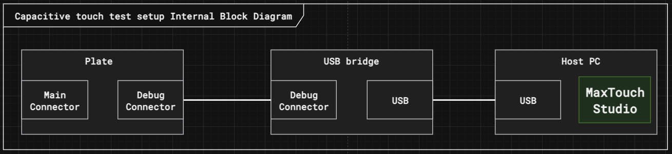
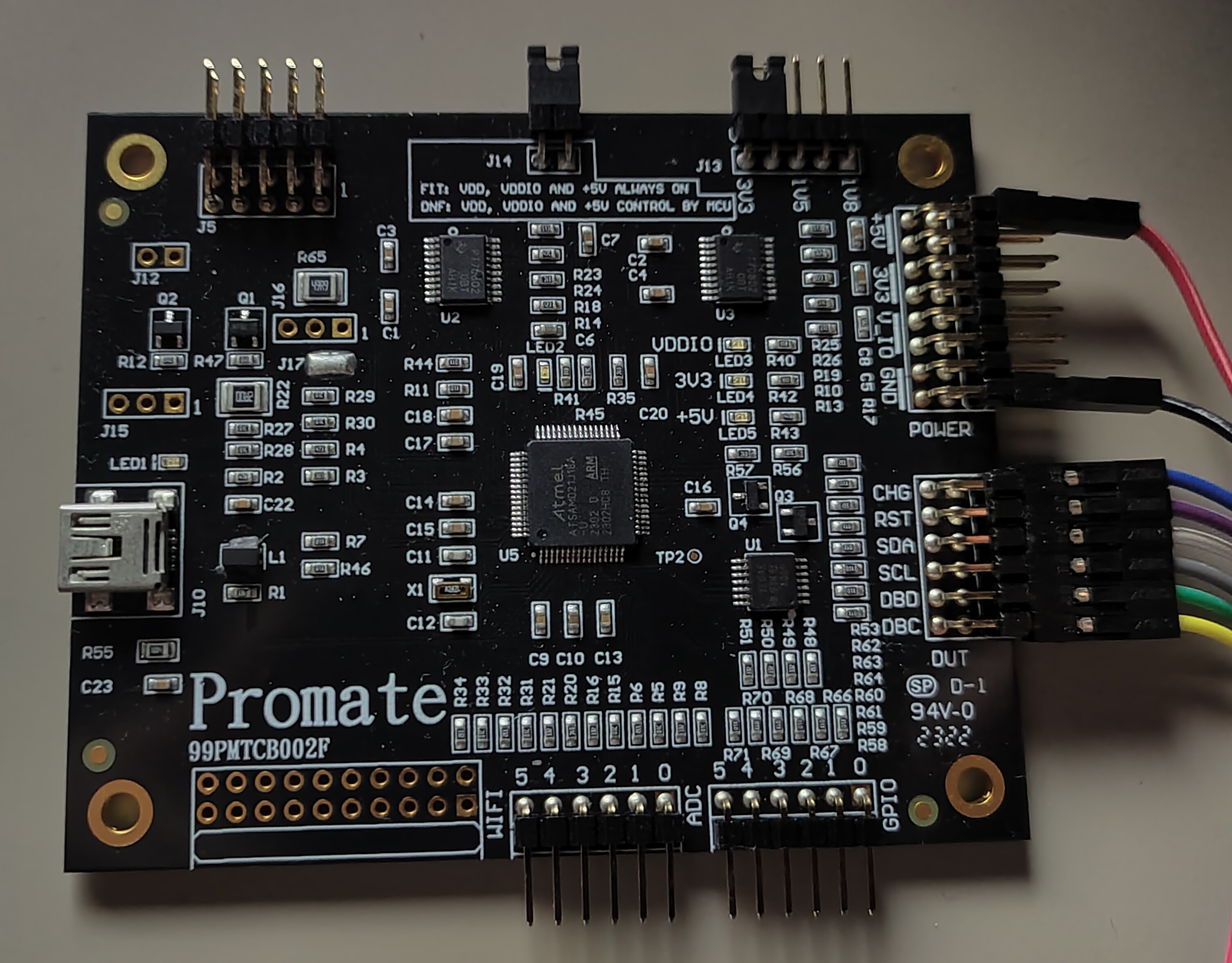
For testing, we will bypass the central controller altogether, and connect the plate to the computer through a USB bridge. The bridge is a PROMATE D21 . It's the cheapest bridge I could find at £78.22.
The reason I'm willing to spend on a device just to verify the operation of something that will be controlled through other means is the number of unknown factors. Let's say I download the I2C device driver for the MaxTouch chip, and start communicating with it through the central controller. If anything goes wrong, I have little idea whether my PCB design went wrong, my I2C bus is busted, the device driver is buggy, or my default configuration is flawed. The fewer unknown factors I expose for a test, the sooner I can conclude. By using an off-the-shelf bridge, and their tuning software, I can eliminate most of the unknown factors.
Test Method
First I tested the 3.3V bus. Applying the right voltage through a test point and see if it's using the right amount of current. Then went onto the 5V source and repeated the test. Once I was confident the board wouldn't burst into flames if I connected it to the bridge I went ahead and prayed it would recognise my board. By some divine miracle, it did! No touch-ups were needed, the connection was straight-up established!
Testing Touch capability
First I tested how well it detected human touch. The measurement was all over the place at the beginning. The reason for that is the mutual capacitance sensor's response to proximity. At first, the capacitance starts slowly decreasing. As the proximity reduces to near zero, the capacitance starts shooting up rapidly as seen in the graph below:
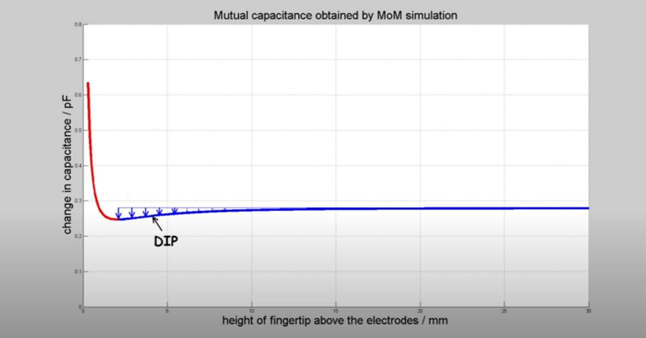
You can learn more about the physics of this phenomena in this youtube video, where I got the graph from.
The sensor only operates in the "dip" region, so to be able to detect my finger I needed to add a couple of layers of non-conducting material between the plate and my finger. (tape in my case for fine-tuning). Once the right dielectric thickness was found, the plate was working quite well to detect my finger. With a bit more work, I could have turned this into a decent touch panel.
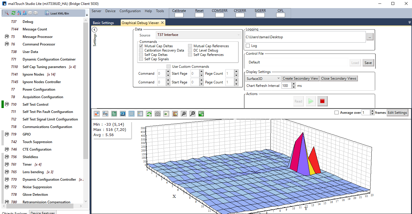
The next video shows on a surface plot what the plate recognizes from my finger:
In the next video, you will see that the response is still great even if I hold a bearing ball in my hand.
|f I'm wearing thick gloves, there is still some response, but not strong enough to be able to detect a singular touch point, so the internal filter just gives up.
Now here comes the interesting bit. If I grab the steel ball with my gloved hand, and roll it around on the sensing surface, there is still too little activation of the sensor to pick up a touch signal.
Why is that? After looking into it I found this: It's not enough for an object to be conductive to be detected by the capacitive sensor, but also needs to be able to disrupt the electrostatic field well enough so that the capacitance change is picked up by the receiver. To disrupt the field, the object would need to be either coupled to the ground or be large enough to make a dent in the electrostatic field. Sadly the bearing ball I planned to use achieves neither. If I increase the size of the ball, the signal gets better, but with the weight limit of the actuators I can't increase it large enough to be usable. This taps into the study of tangibles on capacitive touch screens. Many have tried, but most of them came to the same conclusion: It would need a human to touch the device to be registered.
What's next?
Instead of trying to find the right combination of parameters to squeeze out a detection, I will try out a different detection basis which will be inductive proximity detection. Because the ball is made out of solid steel, there is a good chance of having a strong signal that can be processed into position data. Subscribe to the project if you would like to see the outcome of those tests.
Conclusion
Looks like my idea of using capacitive touch to sense the position of bearing balls was flawed. The object of detection doesn't have all the properties needed for a strong signal. Instead in the future, I will try inductive proximity detection, as the ball has a better chance to disrupt an electromagnetic field than an electrostatic one.
Discussions
Become a Hackaday.io Member
Create an account to leave a comment. Already have an account? Log In.