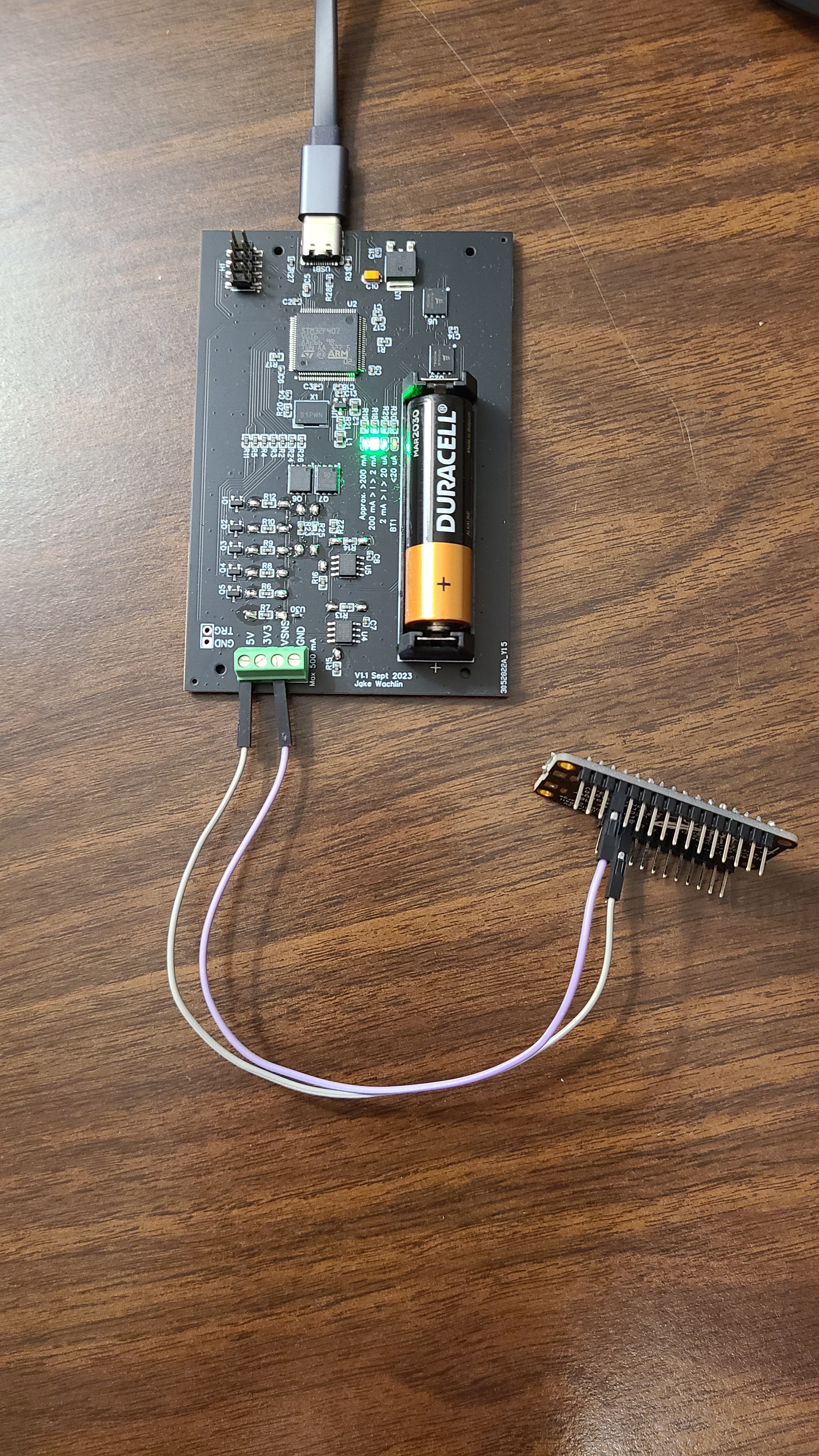
As an example to show MetaShunt's capability, I created an Arduino sketch for the Adafruit Feather M0 Adalogger which would toggle the onboard LED and use various low power modes. This microcontroller development board was then connected to MetaShunt:
Adalogger GND <----> VSNS
Adalogger USB <----> 5V
The code running on the Adalogger is the following:
#include "LowPower.h"
#include <RTCCounter.h>

#define LED_PIN     13

#define CONFIG_PINS     true
#define DISABLE_TC_TCC  true
#define DISABLE_CLOCKS  true
#define DISABLE_ADC     true

void setup() {
  pinMode(LED_PIN, OUTPUT);
  digitalWrite(LED_PIN, LOW);

  #ifdef CONFIG_PINS
  pinMode(0, OUTPUT);
  pinMode(1, OUTPUT);
  pinMode(4, OUTPUT);
  pinMode(5, OUTPUT);
  pinMode(6, OUTPUT);
  pinMode(7, OUTPUT);
  pinMode(8, OUTPUT);
  pinMode(9, OUTPUT);
  pinMode(10, OUTPUT);
  pinMode(11, OUTPUT);
  pinMode(12, OUTPUT);
  pinMode(A0, OUTPUT);
  pinMode(A1, OUTPUT);
  pinMode(A2, OUTPUT);
  pinMode(A3, OUTPUT);
  pinMode(A4, OUTPUT);
  pinMode(A5, OUTPUT);

  digitalWrite(0, LOW);
  digitalWrite(1, LOW);
  digitalWrite(4, LOW);
  digitalWrite(5, LOW);
  digitalWrite(6, LOW);
  digitalWrite(7, LOW);
  digitalWrite(8, LOW);
  digitalWrite(9, LOW);
  digitalWrite(10, LOW);
  digitalWrite(11, LOW);
  digitalWrite(12, LOW);
  digitalWrite(A0, LOW);
  digitalWrite(A1, LOW);
  digitalWrite(A2, LOW);
  digitalWrite(A3, LOW);
  digitalWrite(A4, LOW);
  digitalWrite(A5, LOW);
  #endif

  #ifdef DISABLE_TC_TCC
  TC3->COUNT16.CTRLA.bit.ENABLE = 0;
  TC4->COUNT16.CTRLA.bit.ENABLE = 0;
  TC5->COUNT16.CTRLA.bit.ENABLE = 0;

  TCC0->CTRLA.bit.ENABLE = 0;
  TCC1->CTRLA.bit.ENABLE = 0;
  TCC2->CTRLA.bit.ENABLE = 0;
  #endif

  #ifdef DISABLE_CLOCKS
  SYSCTRL->DFLLCTRL.bit.RUNSTDBY = 0;
  SYSCTRL->VREG.bit.RUNSTDBY = 0;
  #endif

  #ifdef DISABLE_ADC
  ADC->CTRLA.bit.SWRST = 1;
  #endif

  rtcCounter.begin();

}

void loop() {

  // Busy wait
  delay(2000);

  int i;

  for(i=0; i<10; i++)
  {
    delay(250);
    digitalWrite(LED_PIN, HIGH);
    delay(250);
    digitalWrite(LED_PIN, LOW);
  }

  // Another type of sleep
  rtcCounter.setPeriodicAlarm(2);
  SysTick->CTRL &= ~SysTick_CTRL_TICKINT_Msk;  // Disable SysTick interrupts
  LowPower.idle(IDLE_2);
  SysTick->CTRL |= SysTick_CTRL_TICKINT_Msk;   // Enable SysTick interrupts
  if (rtcCounter.getFlag()) {
    rtcCounter.clearFlag();
  }

  delay(500);

  // Then standby
  rtcCounter.setPeriodicAlarm(5);
  LowPower.standby();
  if (rtcCounter.getFlag()) {
    rtcCounter.clearFlag();
  }

  delay(1000);

  for(i=0; i<2; i++)
  {
    delay(500);
    digitalWrite(LED_PIN, HIGH);
    delay(500);
    digitalWrite(LED_PIN, LOW);
  }

}
This code toggles LEDs and uses active mode (in delays), idle, and standby power modes.
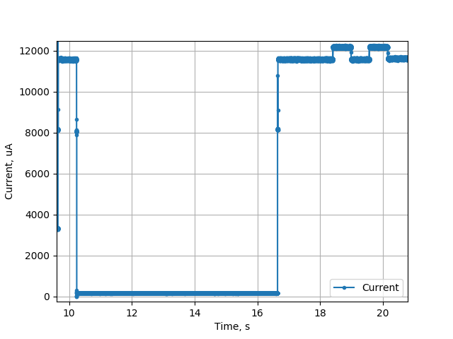
Using the Python interface script that will be released soon, data was recorded for 20 seconds. The output data was provided at 4kHz (the onboard measurement is much faster, but USB bandwidth limits the output data rate to this level). The overall data cycle is shown below.
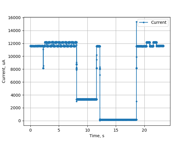
Let's look specifically at sections of the code and see how they match to the current profile shown here. The first section involves a 2 second busy wait followed by toggling the LED pin 10 times with a 0.5s period.
// Busy wait
  delay(2000);

  int i;

  for(i=0; i<10; i++)
  {
    delay(250);
    digitalWrite(LED_PIN, HIGH);
    delay(250);
    digitalWrite(LED_PIN, LOW);
  }
The plot below shows the measurements during this portion of the program. During the busy wait, the current is ~11.6mA, and it increases to about 12.2mA when the LED is turned on.
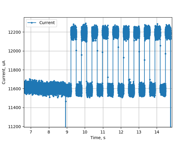
In the next section, the Idle 2 sleep mode is used. This sleep mode is set for about 2 seconds. Then a 500ms busy wait occurs.
// Another type of sleep
rtcCounter.setPeriodicAlarm(2);
SysTick->CTRL &= ~SysTick_CTRL_TICKINT_Msk;  // Disable SysTick interrupts
LowPower.idle(IDLE_2);
SysTick->CTRL |= SysTick_CTRL_TICKINT_Msk;   // Enable SysTick interrupts
if (rtcCounter.getFlag()) {
    rtcCounter.clearFlag();
}

delay(500);
The measurement profile for this portion of the code is shown here. The current in Idle mode drops down to below 4mA, and back up for 500ms during the busy wait.
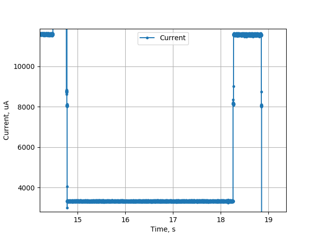
In the final portion of the code, the system enters standby for 5 seconds, followed by 1 second busy wait, and toggling the LED twice at 1Hz.
// Then standby
  rtcCounter.setPeriodicAlarm(5);
  LowPower.standby();
  if (rtcCounter.getFlag()) {
    rtcCounter.clearFlag();
  }

  delay(1000);

  for(i=0; i<2; i++)
  {
    delay(500);
    digitalWrite(LED_PIN, HIGH);
    delay(500);
    digitalWrite(LED_PIN, LOW);
  }
The profile for this section is shown in the next image. When in standby, the current drops very low for about 5 seconds. The busy wait and pin toggling are also visible.
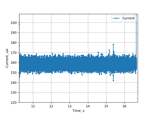
The standby mode current can be focused on as well. In the lowest power mode, the current is about 160uA - not very low but not bad for a development board not specifically designed for low power!
This example doesn't show all of the capabilities of MetaShunt. In particular, the ratio between the peak and minimum current is only about 75:1. A simple current shunt could measure this with reasonable accuracy, This tool is designed to handle variation across much wider scales, up to approximately 10,000,000:1. Future examples will show systems with significantly larger variation between peak and minimum current, as well as examples of the use of this tool in optimizing a low power system.
Discussions
Become a Hackaday.io Member
Create an account to leave a comment. Already have an account? Log In.