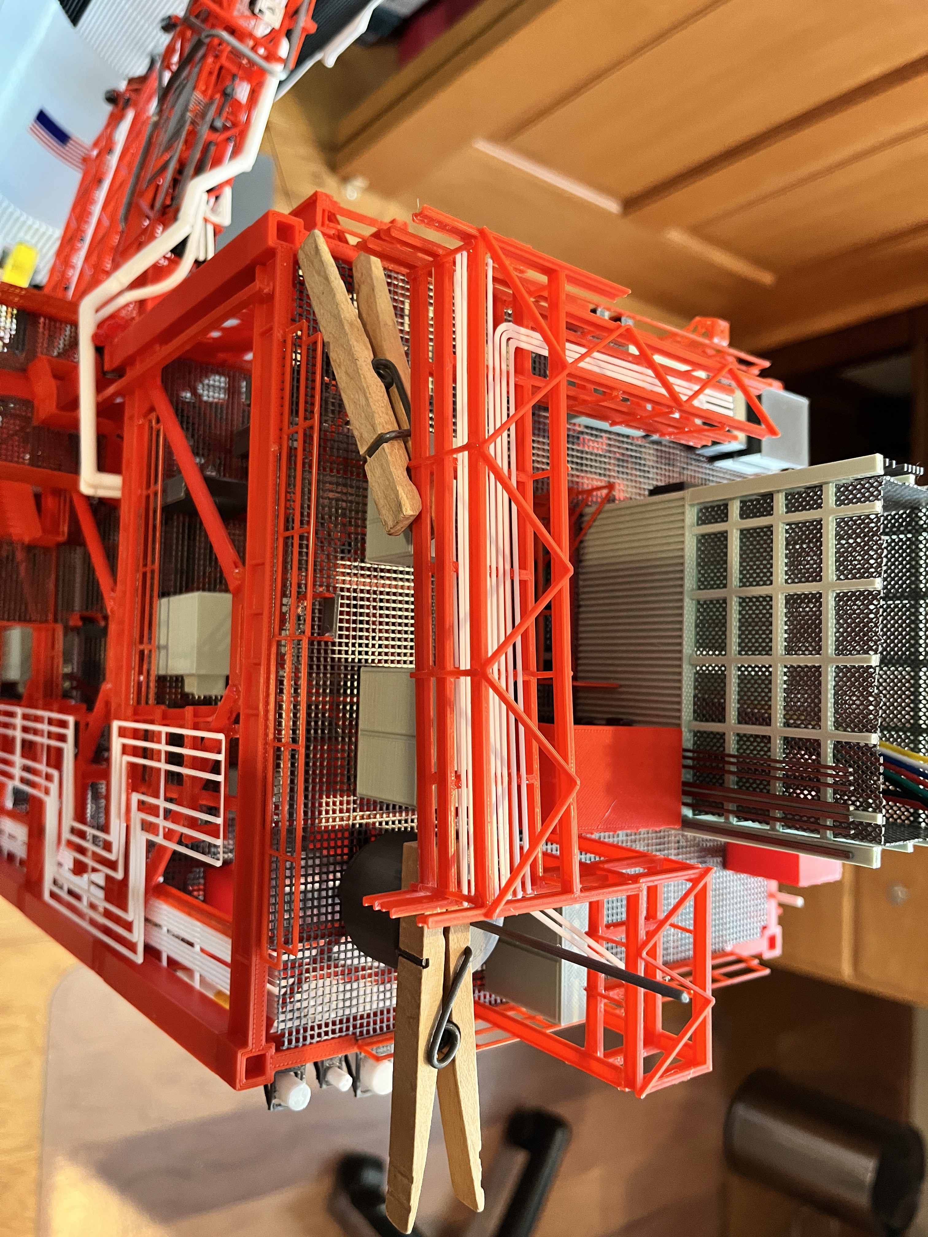
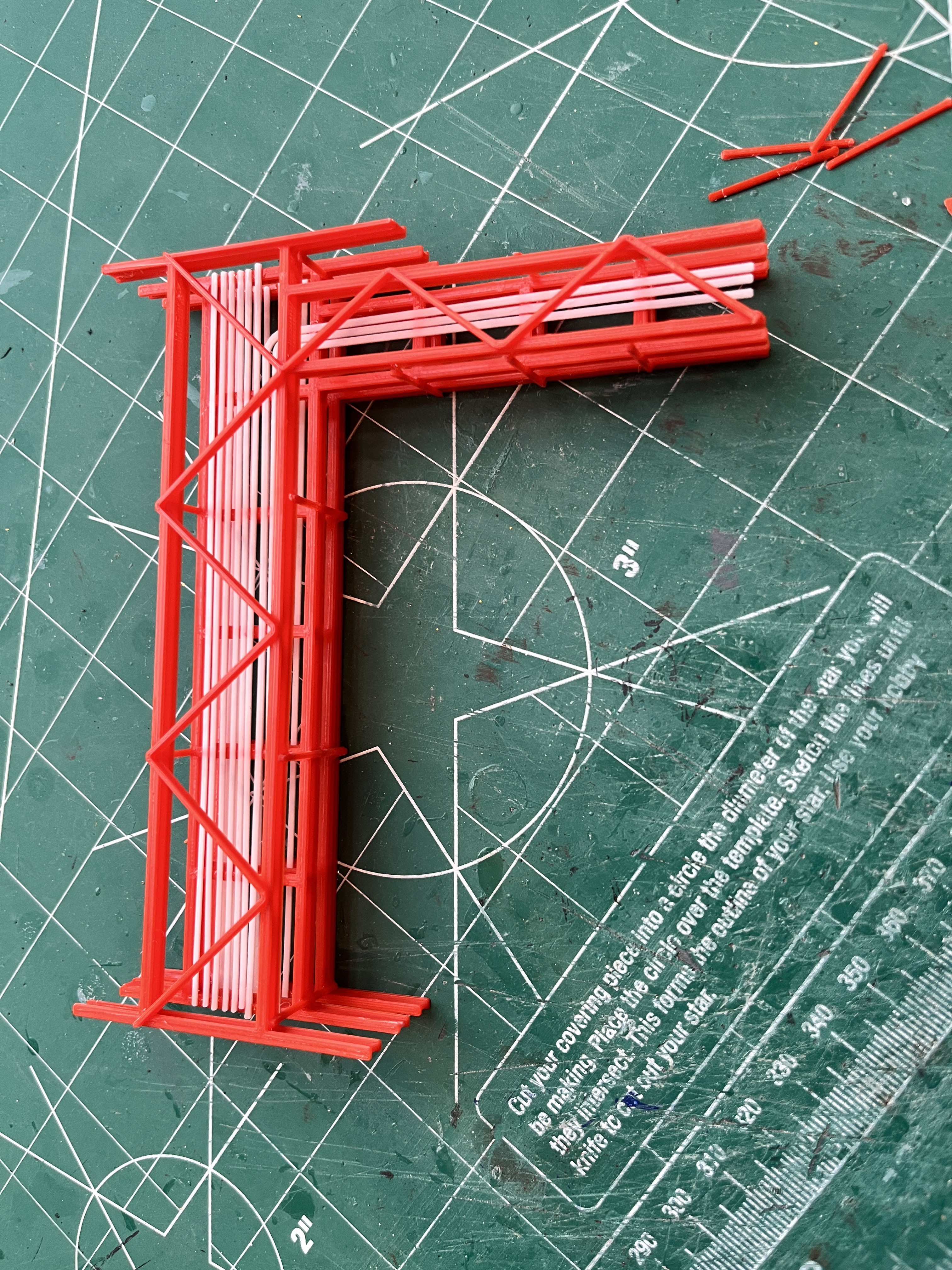
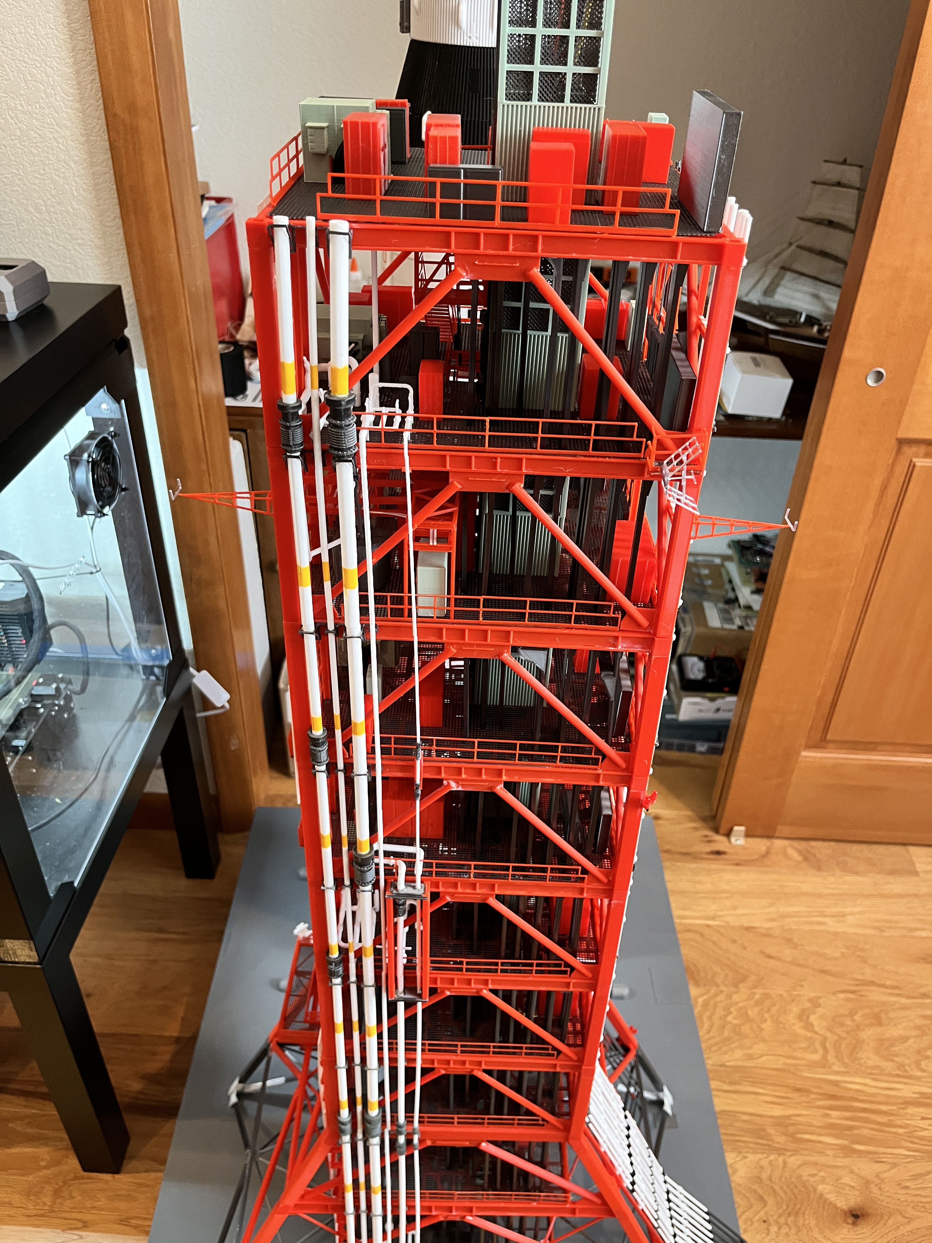
Level 190: The upper three cable floors are assembled and the pipes in place. The lower part has already been glued to the L180 floor. Because this is where tower sections 3 & 4 split, the upper part will be glued to the underside of L200. Here it is held in place with clothes pins.
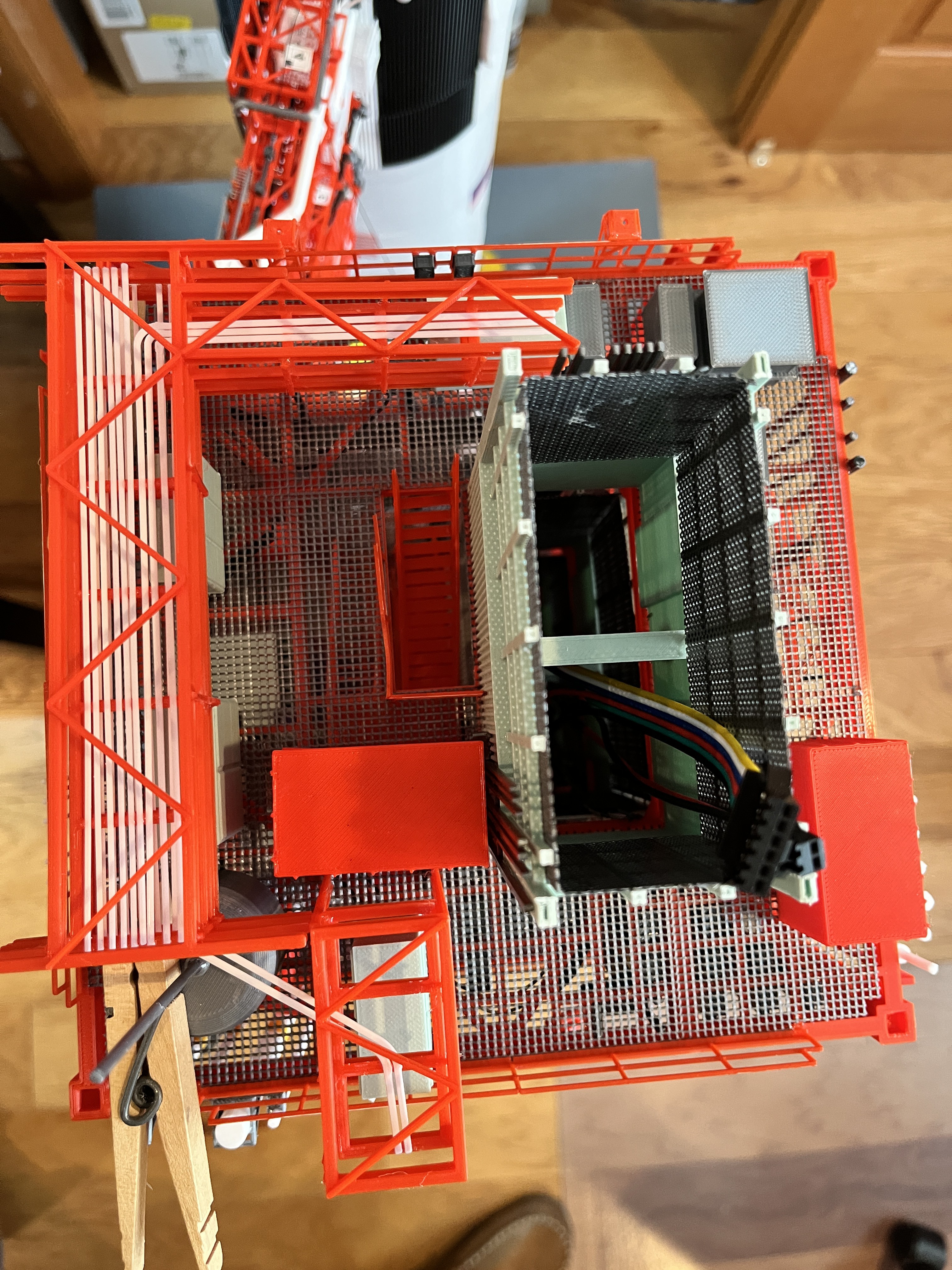
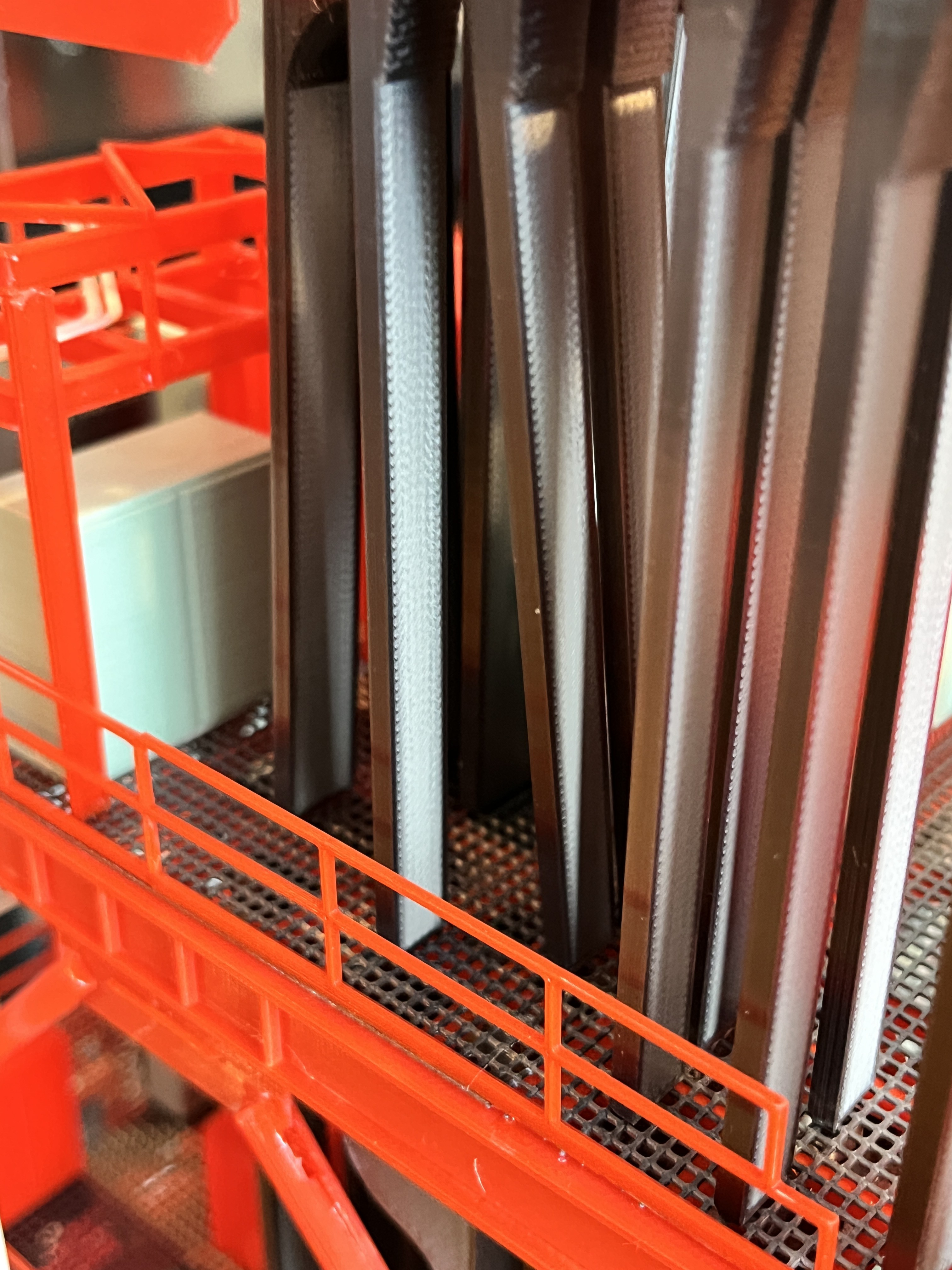
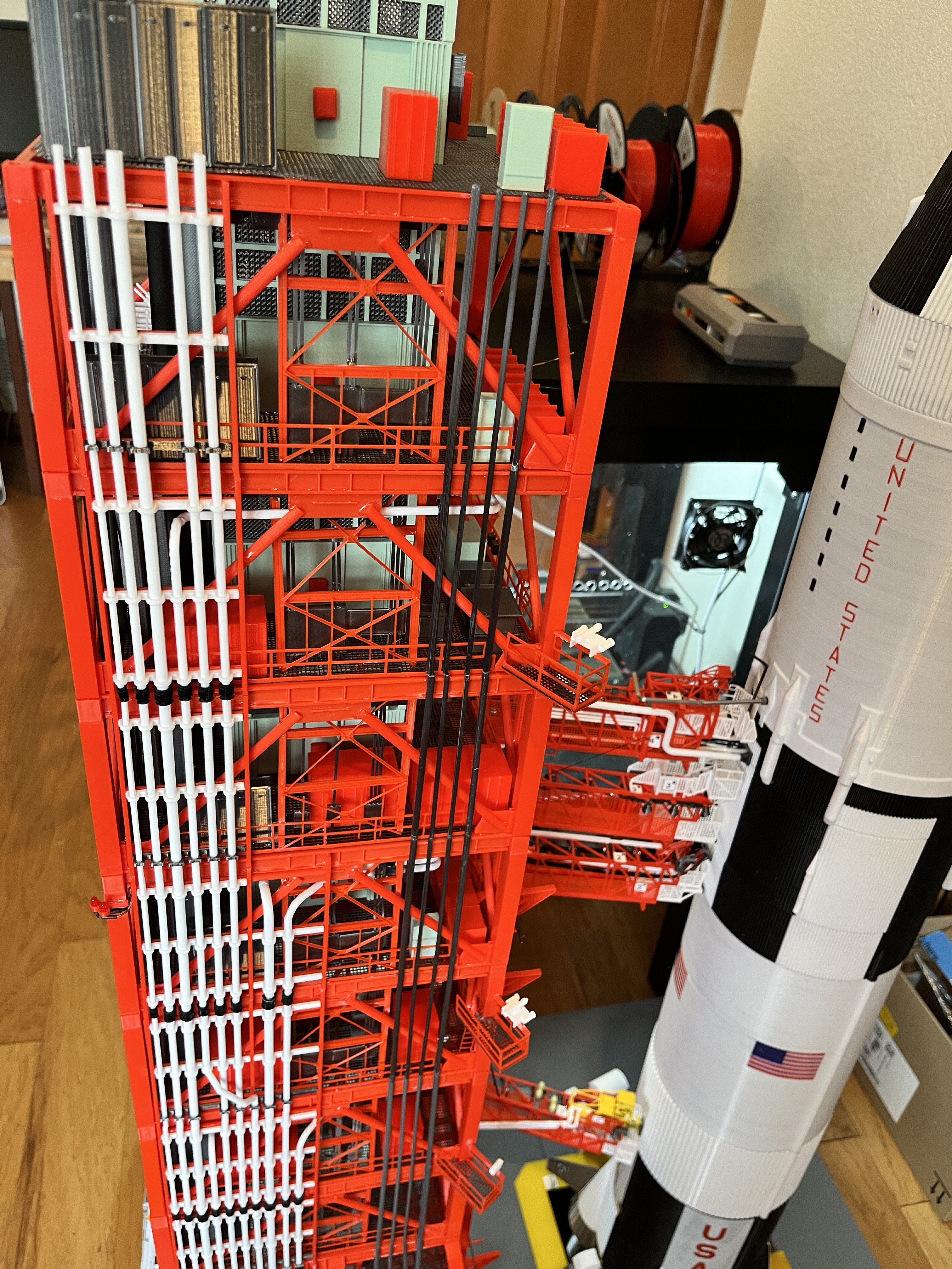
George asked about the angled cable trays. Here are pictures the cable trays for level 180-200. In the first picture you can see CT12 moving over one slot closer to the elevator. In general the wider CTs are bunched up against the back side of the elevator shaft. Two levels lower CT4 ended and CT12 is moving over to take its place. The thinner CTs are bunched towards the outer edge of side 3. One level lower CT 18 ended so at this level CT14 and CT19 moved over one slot. See the next two pictures. In the last picture you can see the end result of the CTs at level 200 before the floor grating is added. From this view you can see that at this level both CT11 and CT7 have ended. You can see how important it is to get the light placement correct so all these cable trays can be glued in without interference.

Here are the lights for L200 glued in. Notice that I chose to no longer add the black shrink wrap. I think this is a cleaner install and would suggest you do not use shrink wrap. When the lights are glued to the cross braces, the brace keeps the two terminals separated and the resistor is soldered onto the positive wire a bit away from the negative terminal. Use the diagram below in the picture to get the light placement correct. I highlighted the horizontal cable trays in orange. Remember that you will be placing the lights with the floor upside down. It really helps to have the actual cable trays printed so you can dry fit them while placing the lights. It helps to place a small black dot where the lights will be glued. I solder up the entire light strand before gluing them in place.
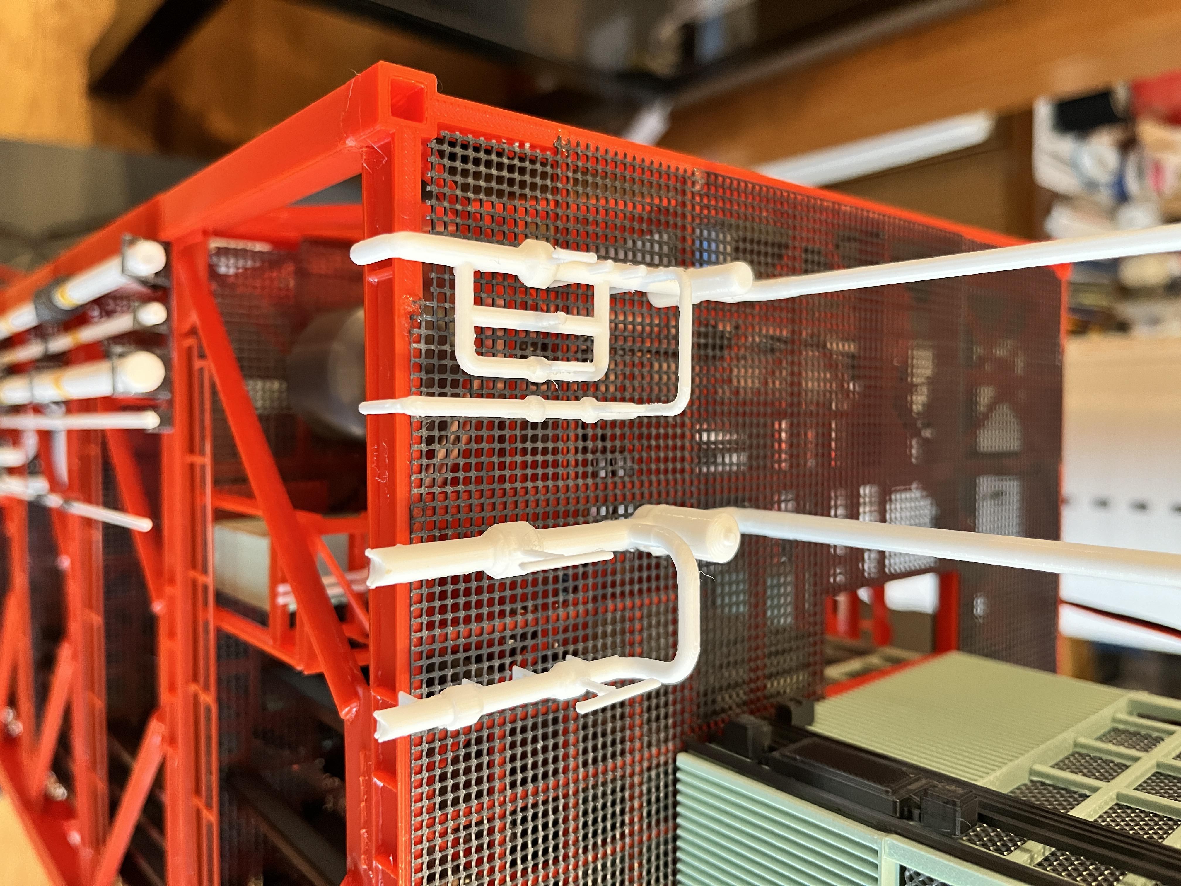
I got to the L200 valving and there is an issue with the LOX valving. Up to this point I have been using the Aviator67 valving and have appreciated the fact that I don't have to design these parts. Unfortunately the valve pipes are too large at this level. I think this may be due the farscape1 pipes being the same size all the way up. and not getting smaller as you go up the tower. Here is a picture of how far off the pipe size is.
Here is the NASA diagram for this valving. Notice that the pipes are 6" and 4" in diameter. This translates to 2.54mm and 1.69mm. The Aviator67 part has these pipes at 4mm and 3mm.
The Aviator67 part also did not include the pipes between the two main pipes and did not take into account that these two pipes end at this level so they should down turn. Here is a picture of the two valving pieces side by side. You can see the obvious difference in pipe size.
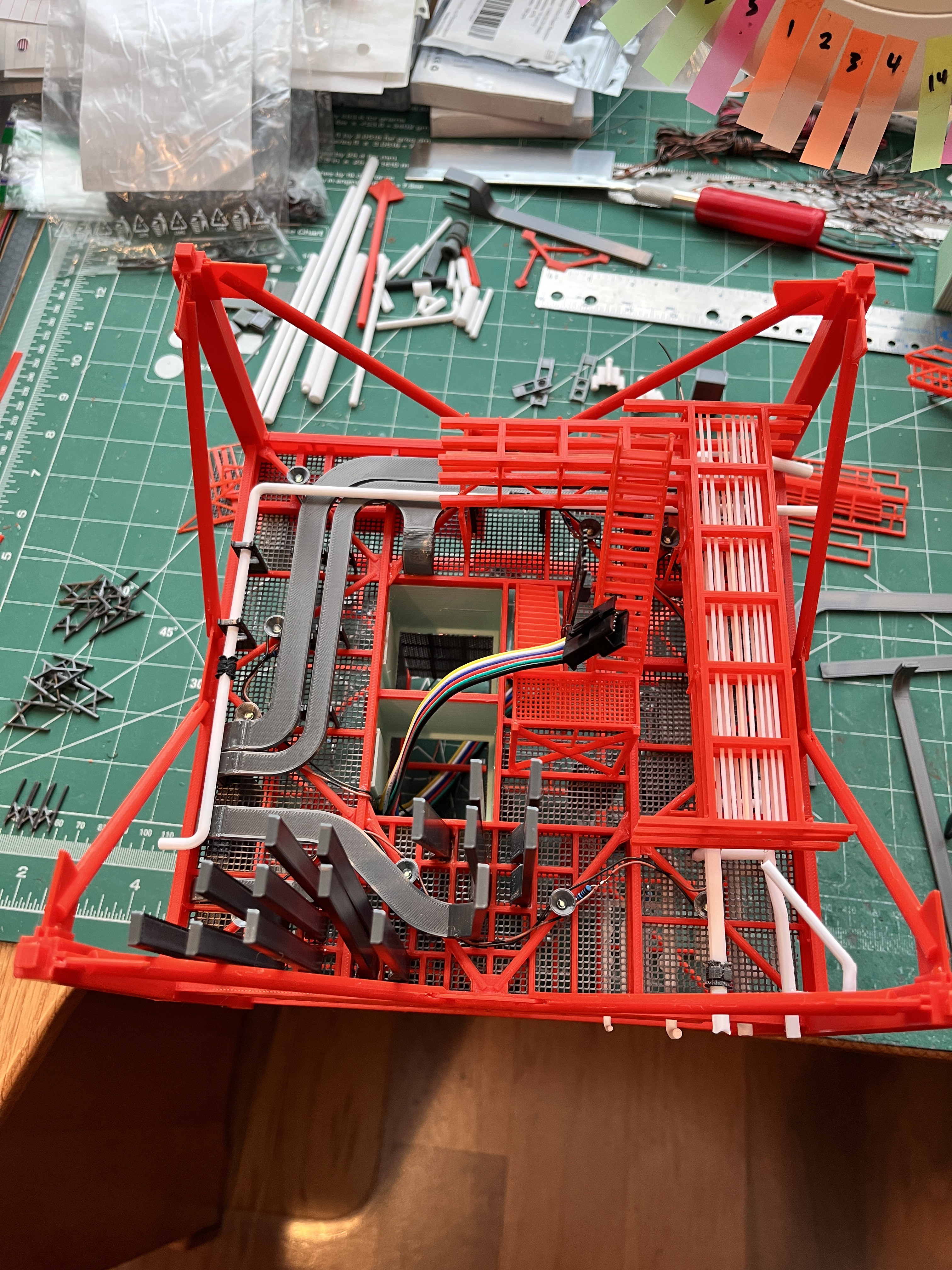
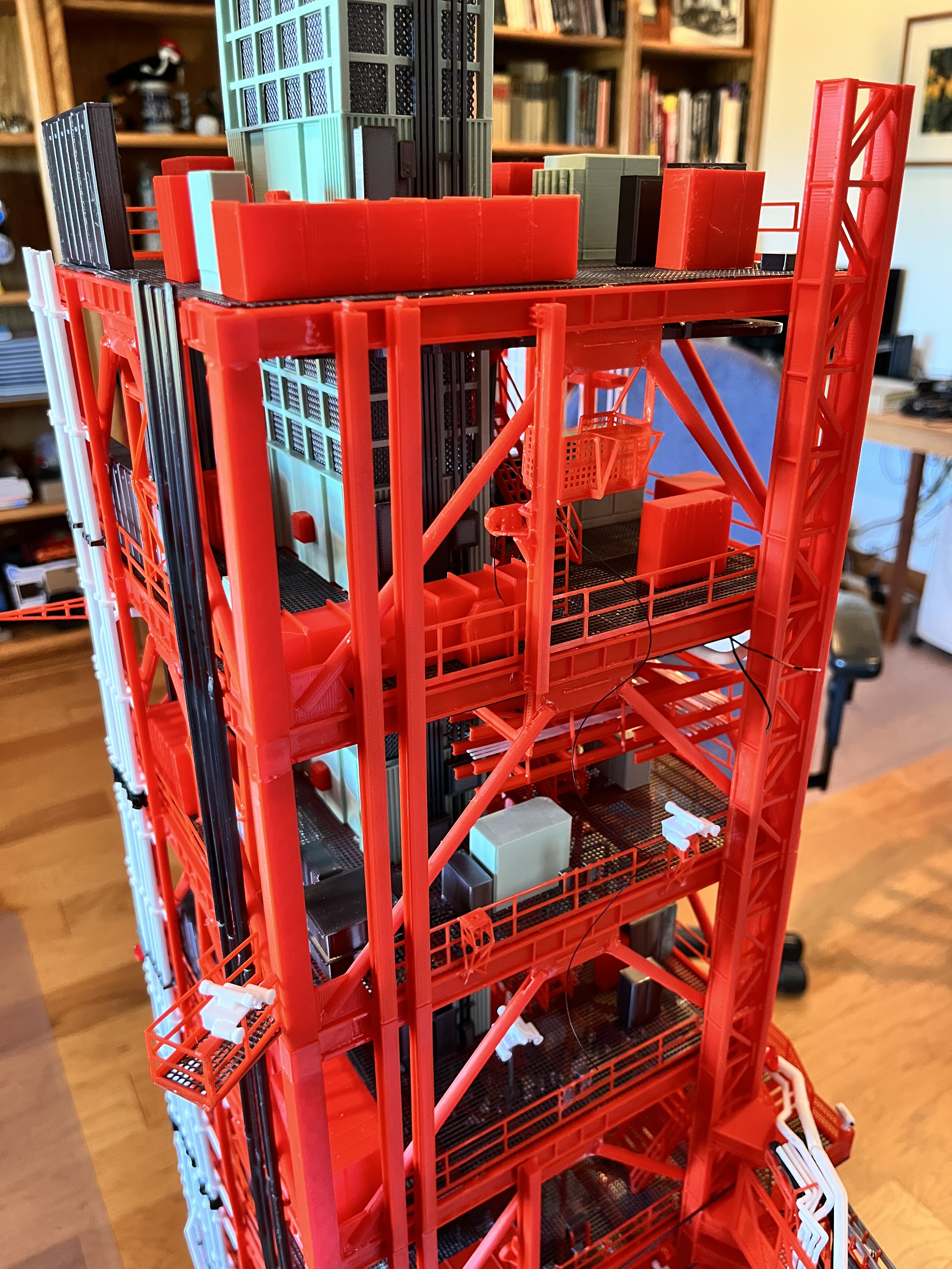
Tighten you belt and sharpen your exacto knife because level 200 is the hardest yet. It is really fortunate that this level is removable from the one below it. The underside has plenty of pipes to deal with. The underfloor pipes that attach to the LH2 valving above was interesting. Fortunately the lighting did not get in the way. From the top view there is one storage rack that is missing by the corner of the elevator.


I was about to add the vertical cable trays between levels 200-220 when I noticed an error in the large cable trays below. They were shifted over one slot. I was able to correct this easily be removing section #4 and ungluing three of the cable trays and gluing them to the correct slots. The center two stayed in place. Here is the corrected picture of the underside.
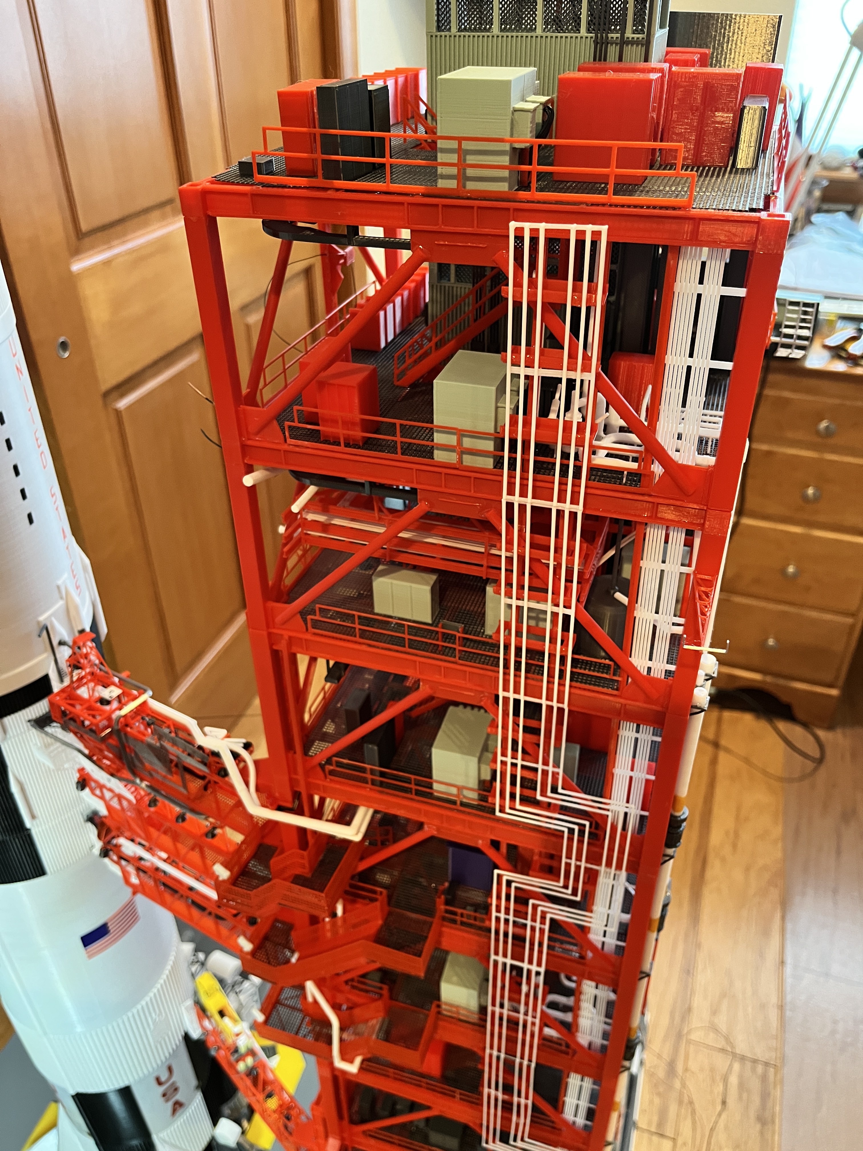
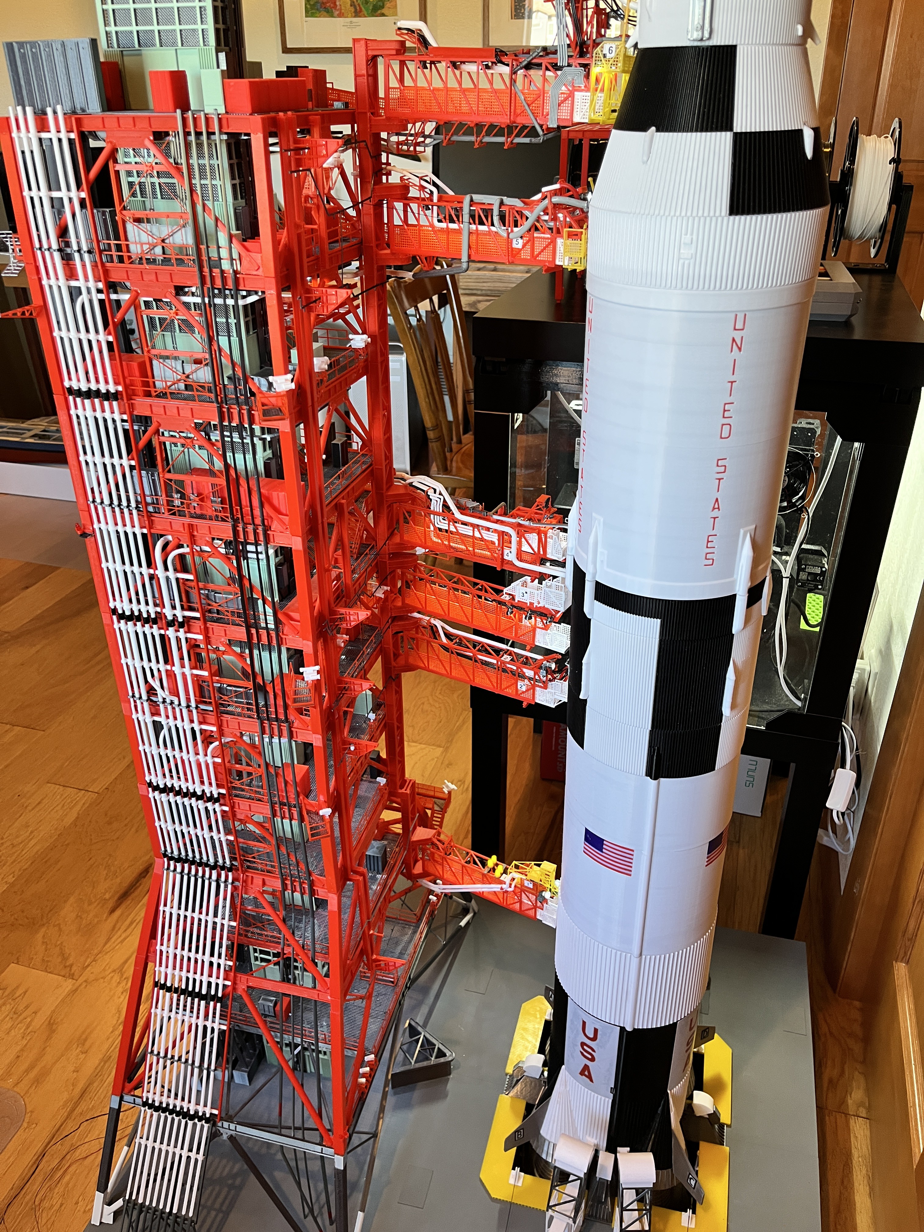
Section #4 core is complete. This includes the structure, flooring and railing, equipment, internal piping, cable trays, elevator and stairs. As I work my way up the tower, I am finding a few errors in my work and some missing parts, but the assembly for the most part is going well. Now its on to the external piping and other outer doodads.


Section #4 Side 2: Complete including another camera platform.
Section 4 Side 4 has its pipes on as well as the antenna and anemometers.

Section 4 Side 3: The LOX pipes have ended. The cable trays have gone from 22 to 10 and the ECS pipes have gone from 10 to 5.
Section 4 Side 1: Yet another camera platform. I guess you can't have too many cameras.
Section #4 Complete: This section went well. Only 3 more sections (8 more levels, 4 more arms and the crane) to go.


Discussions
Become a Hackaday.io Member
Create an account to leave a comment. Already have an account? Log In.