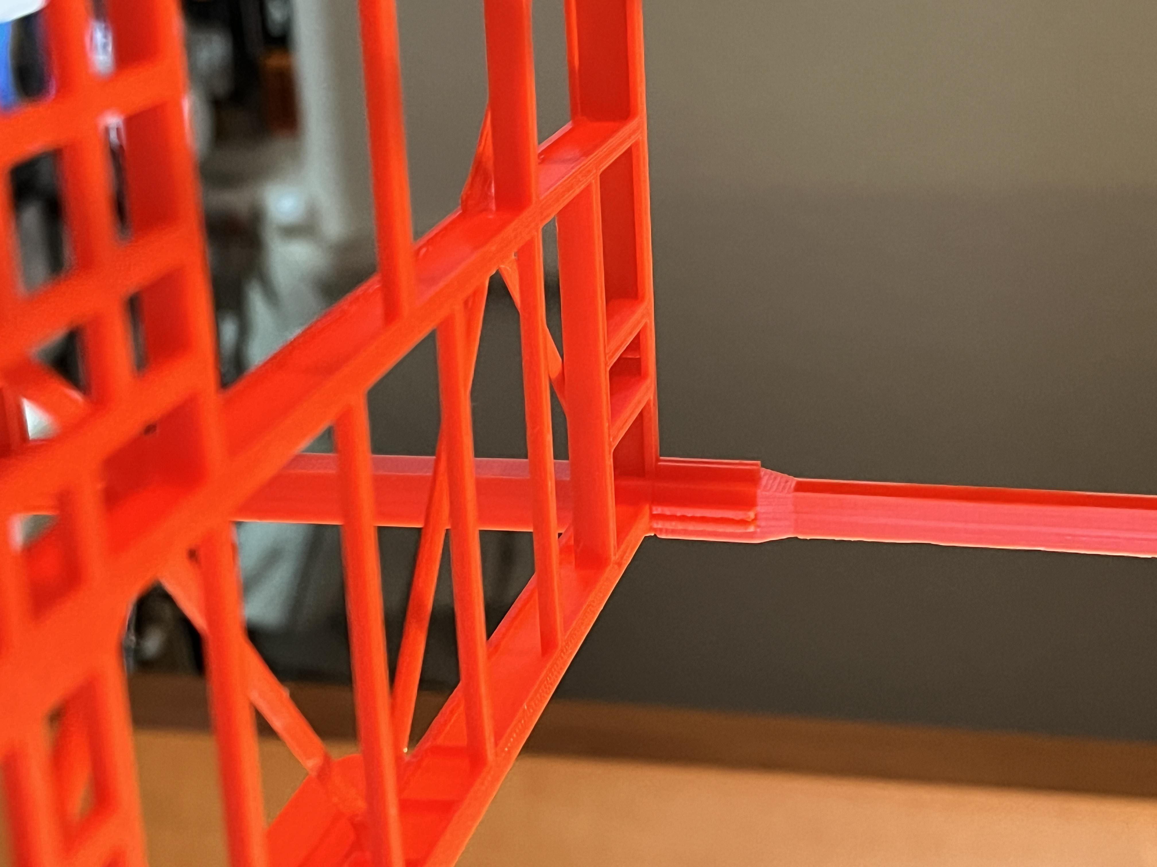
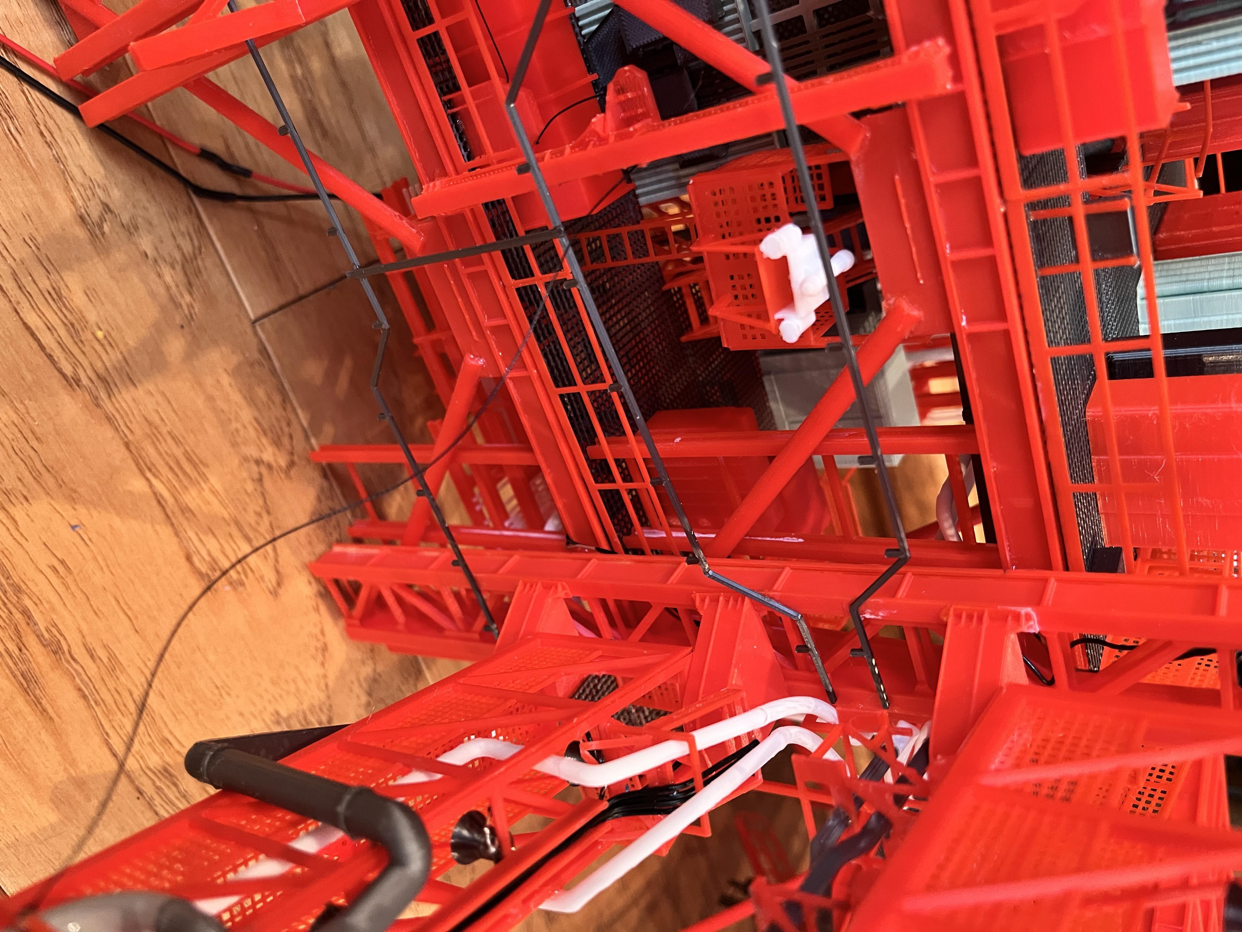
As I work on Swing Arm #6 the printers are busy printing parts for the next section. The next section (#5) has an issue. This section was going to consist of the next 3 floors, L240, L260 & L280. At L260-280 the leg columns switch from box beams to I-beams. Once the columns are I-beams, there can no longer be a square peg to secure the legs to the floors. You can see where I designed these legs to fit into the floor above, however the legs simply sit on top a smooth floor surface.
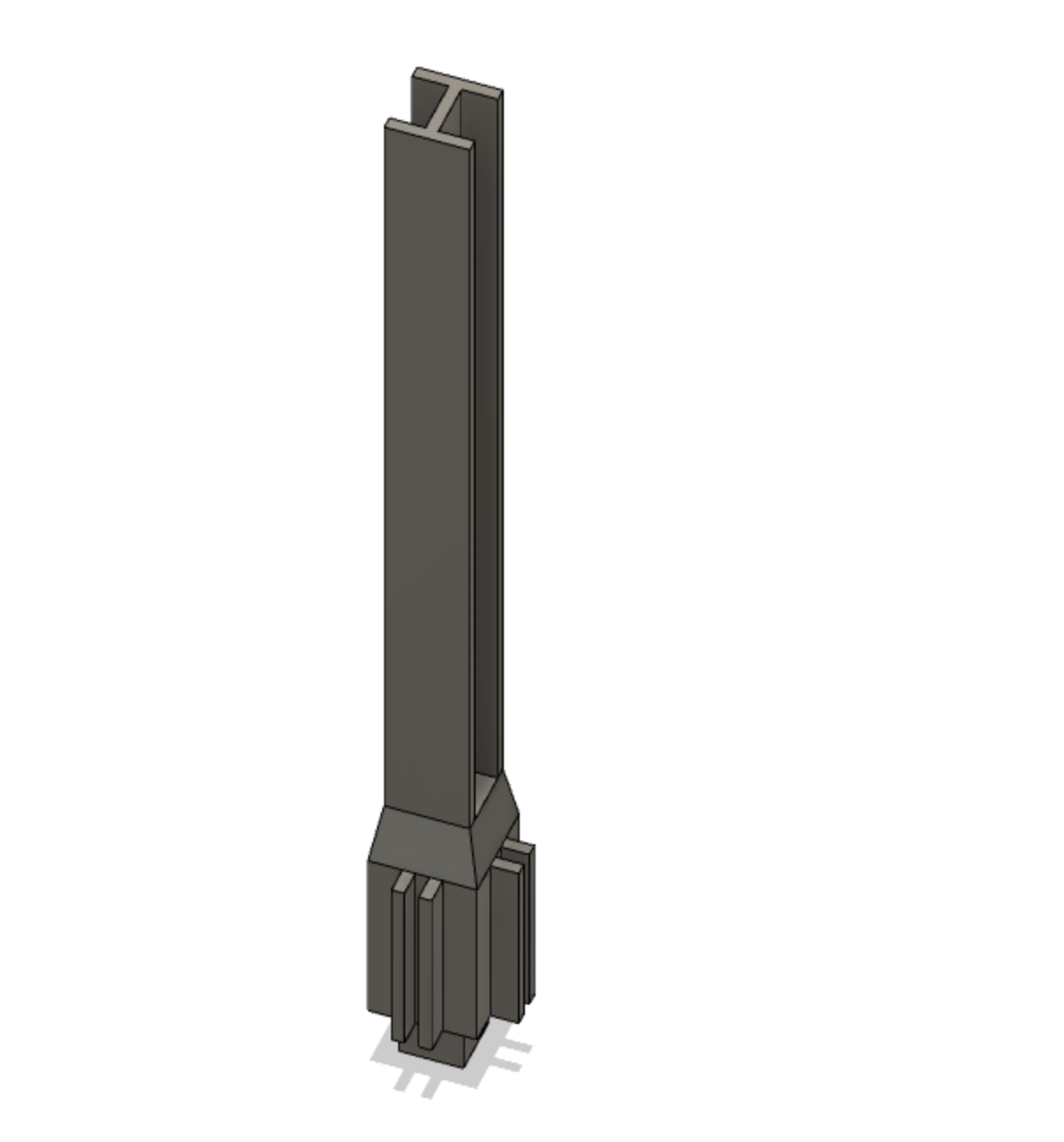
The way I am going to pivot is to have section #5 consist of the next two floors with section #6 going from 2 to 3 floors. This is the last opportunity to take advantage of the peg legs. So section #5 will consist of L240 and l260. Section #6 will consist of L280, L300 & L320. As a result, section #5 will not have any swing arms and section #6 will have swing arms #7, #8, #9 and the DRRS arm that hold the top of the rocket in place. These two section should be very secure. This leaves the final section (#7) the same, consisting of L340, L360, L380 and the crane. I will need to redesign the way these levels connect, maybe setting the bottom of the legs into the floor a bit and add a V-notch to help stabilize the section. The other important aspect will be to balance the crane so it is not "beam heavy". I see this accomplished by gluing washers or some other heavy objects inside the rear of the crane to offset the beam.
Looking ahead to Section #5: With the recent design pivot this section will consist of two floors (L240 & L260) and one swing arm (#7). The arm will attach to an extended support column just like with section #4. This section should be very similar to section #4 except there is only one swing arm. The LH2 pipes will end with this section. This section should go faster than the previous section.
Level 240 core is complete. This is a pretty easy floor because there are no cable trays hanging from the underside of the floor. The E3 pipe goes over towards the next swing arm. The aviator67 pipes for the heat exchanger are sized correctly so all I had to do was design the underside piping. You can see the underside expansion joints on these pipes. I reused the E3 (large) expansion joints. This will be the end of the LH2 pipes. I had to design the two equipment parts related to the round heat exchanger.

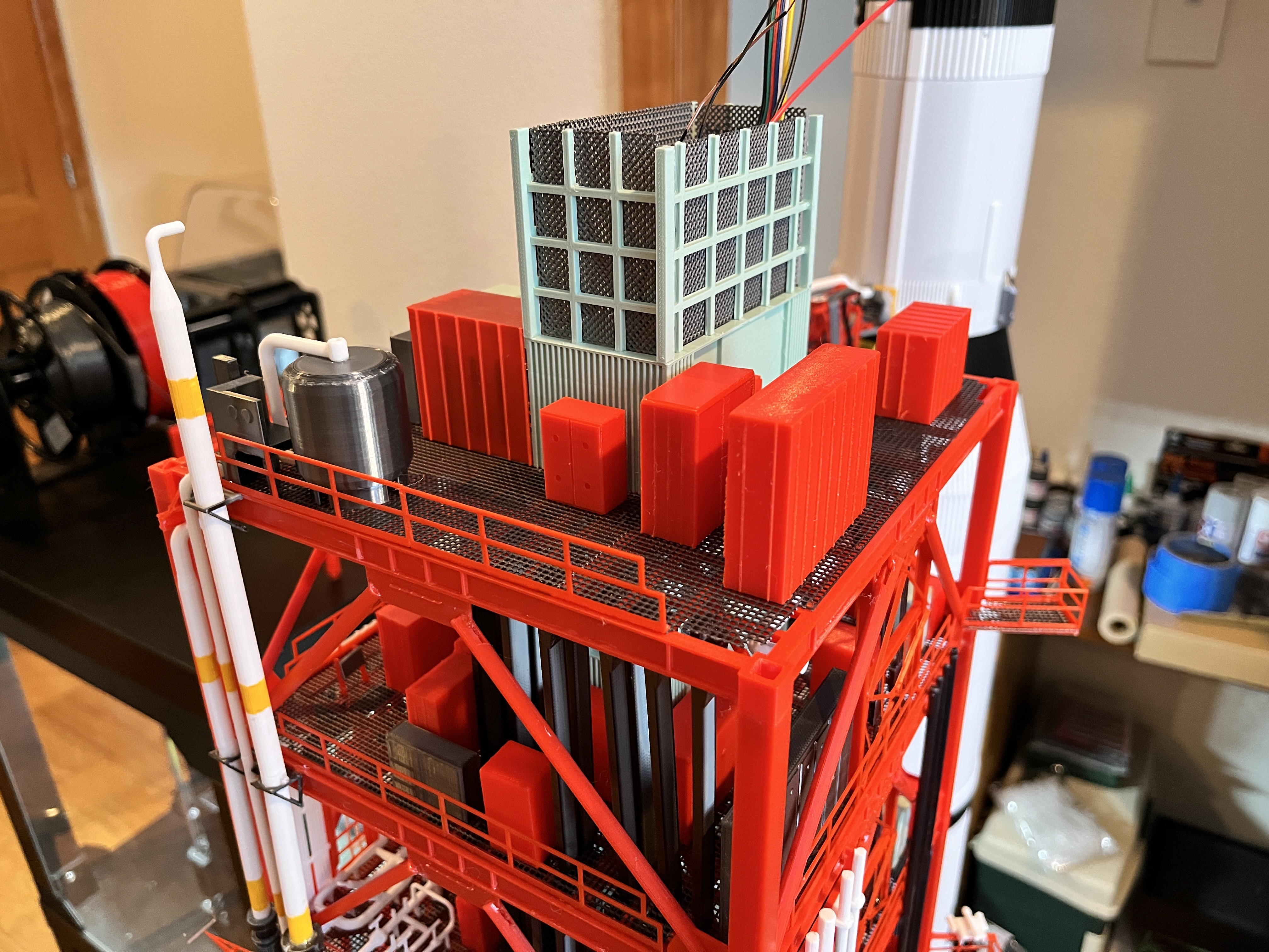
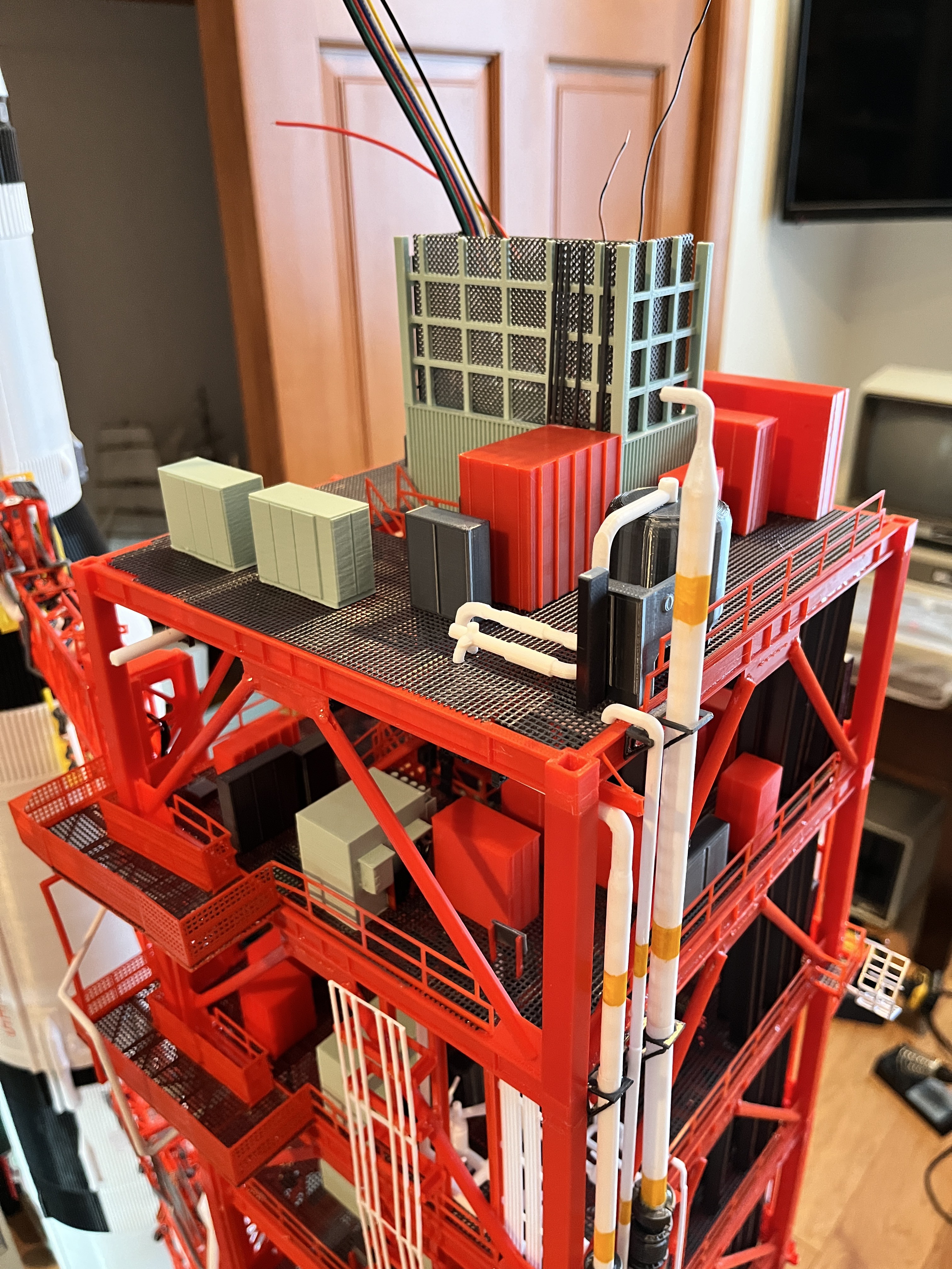
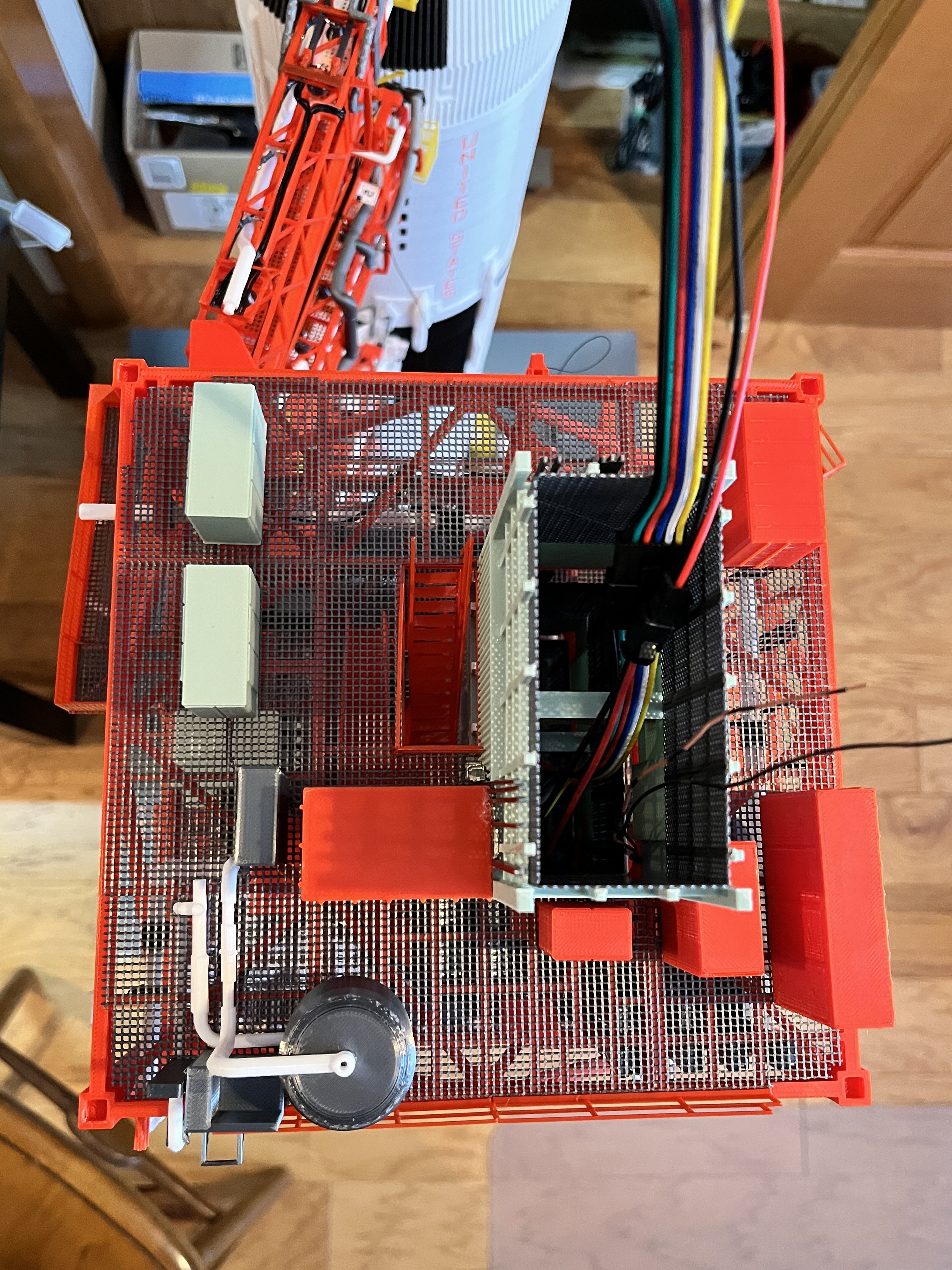
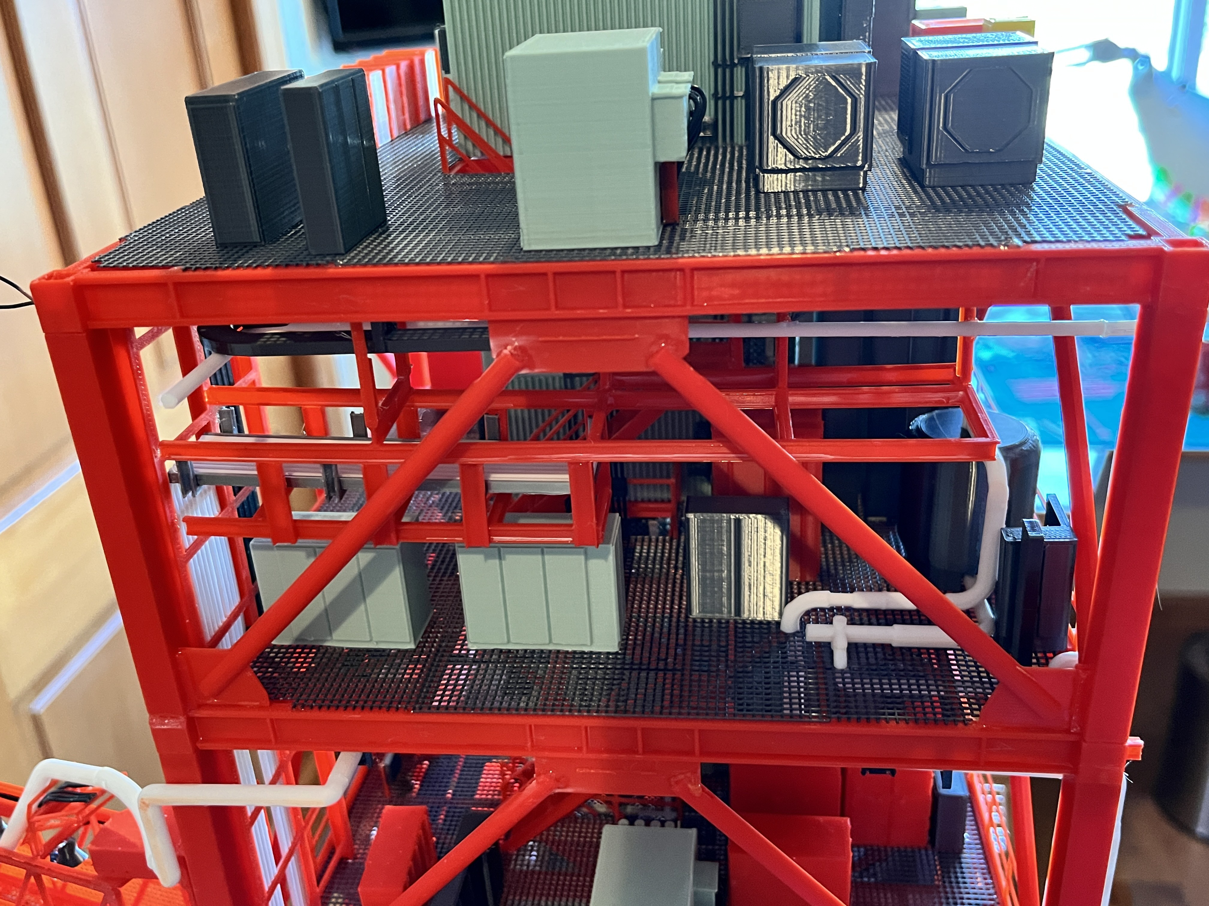
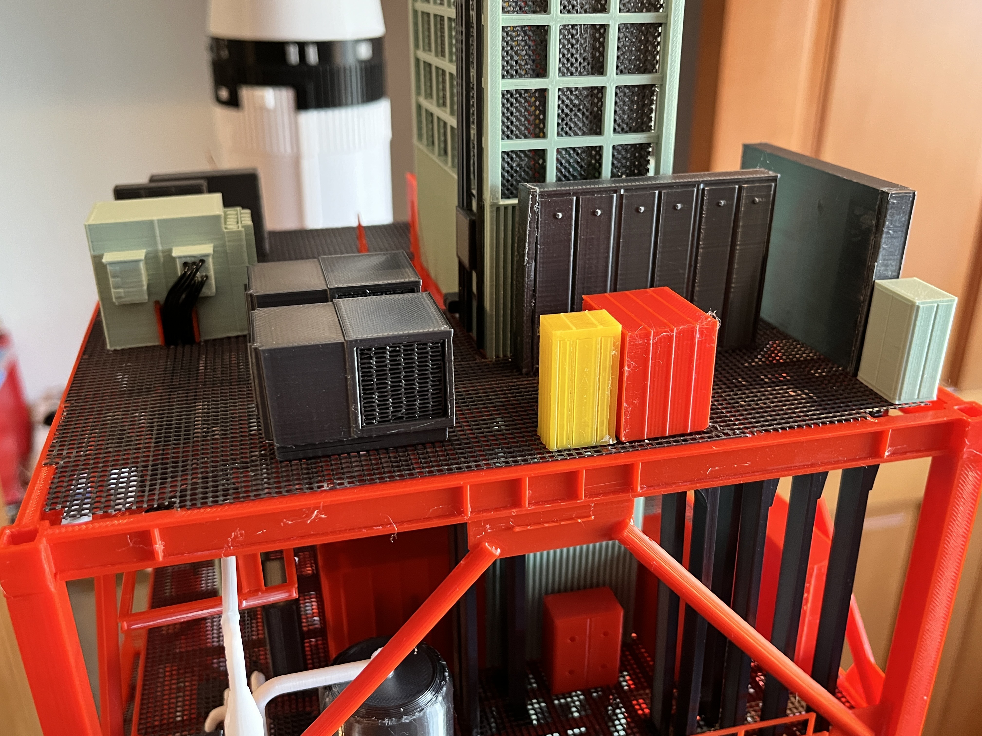
Thanks to aviator67 we have a great looking pair of Water Methanol Units for Level 260.

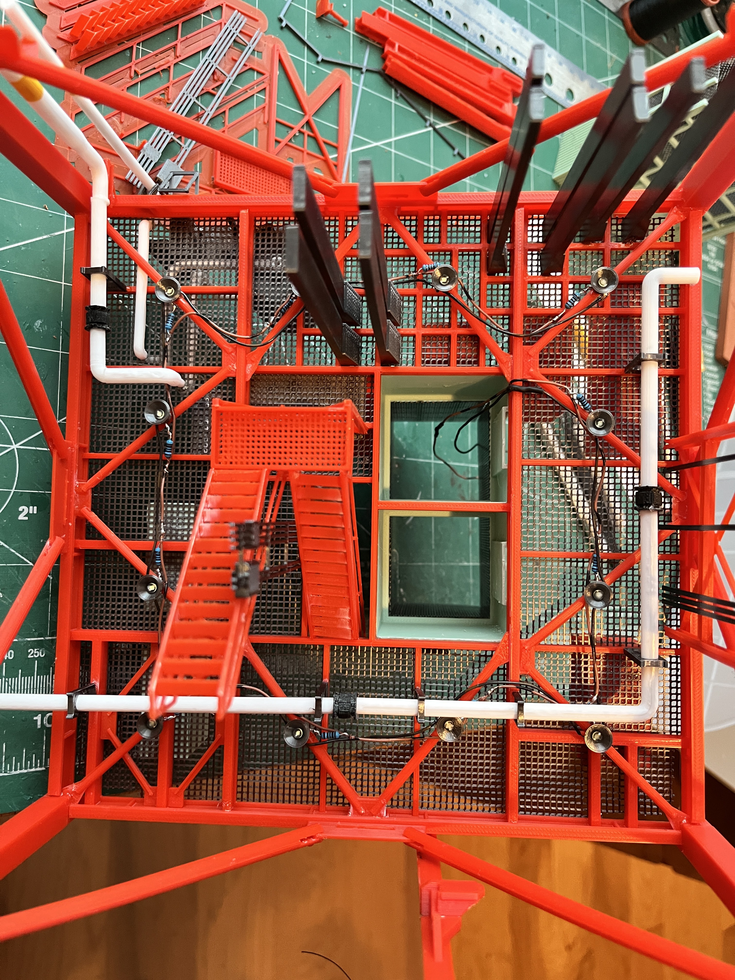
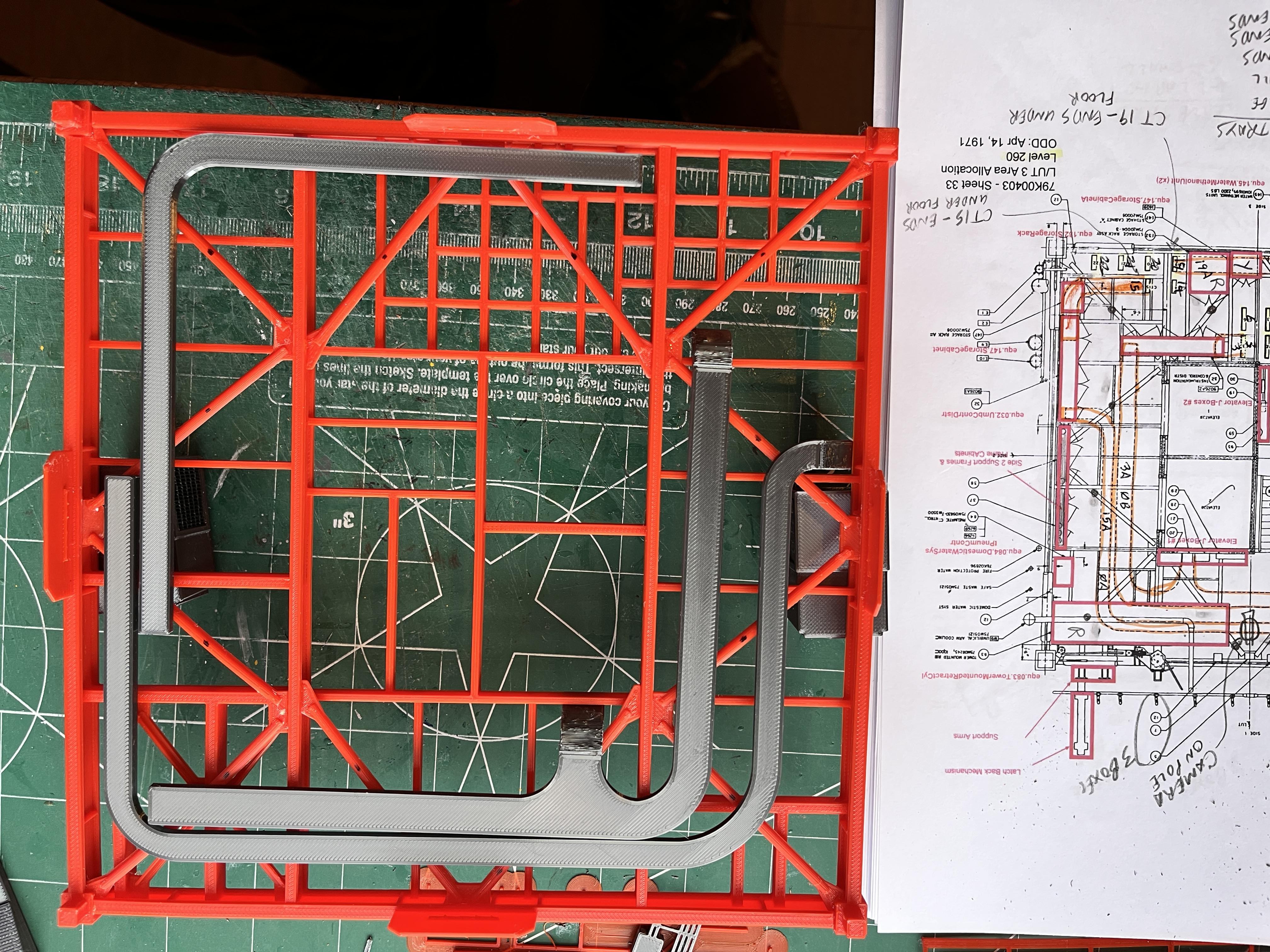
Lighting How To: I get smarter the further I go up the tower. Using the level diagram, place the underfloor cable trays onto the floor I-beams. Notice that the floor is upside down and the drawing is right side up. Once you are satisfied that the cable trays are placed correctly, mark the location of each light using a black marker. Each light will be glued over a dot. The ideal location is in the middle of the cross brace. Sometimes the lights need to be moved so they aren't covered by the cable trays. Now it is easy to create the light string and glue them correctly in place, knowing that when it is time to glue on the cable trays they won't conflict with the lights.
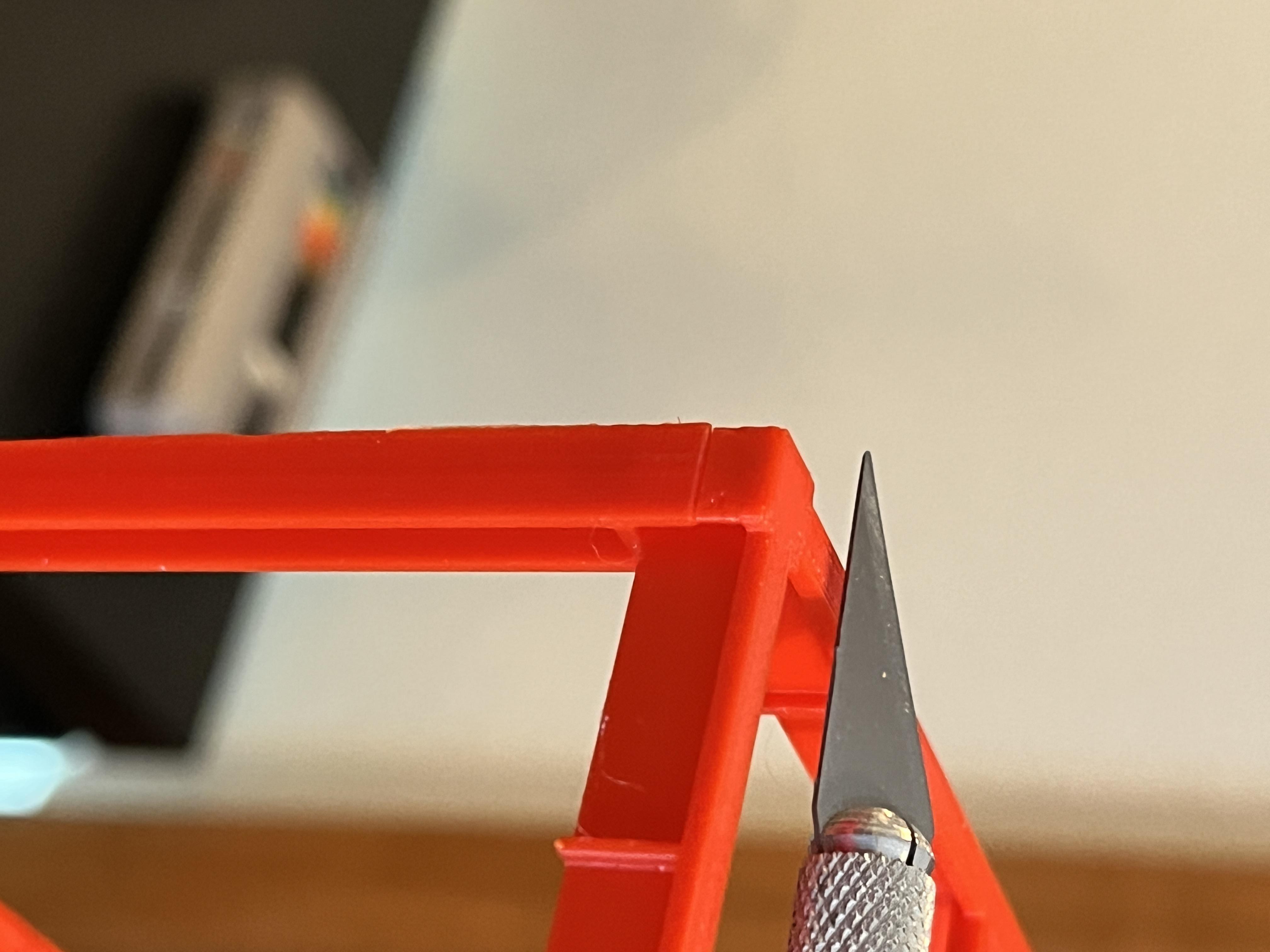
When trying to decipher all the parts I forgot to add the Side 1 cable supports. Those were redesigned into parts that are easier to print along with the actual cables. The easiest way to add these was to remove Sections #4 and #5 from the tower and deal with them separately. You can see the cable supports behind the swing arm support column. The cables are printing. It has proven to be really useful to have the sections removable.

The core part of Section #5 is complete. This includes another intermediate level, L252. Here are pictures of this level constructed outside the model and then installed. The equipment that sits on top of L260 is installed. I really like the Water Methanol Units that aviator67 created.
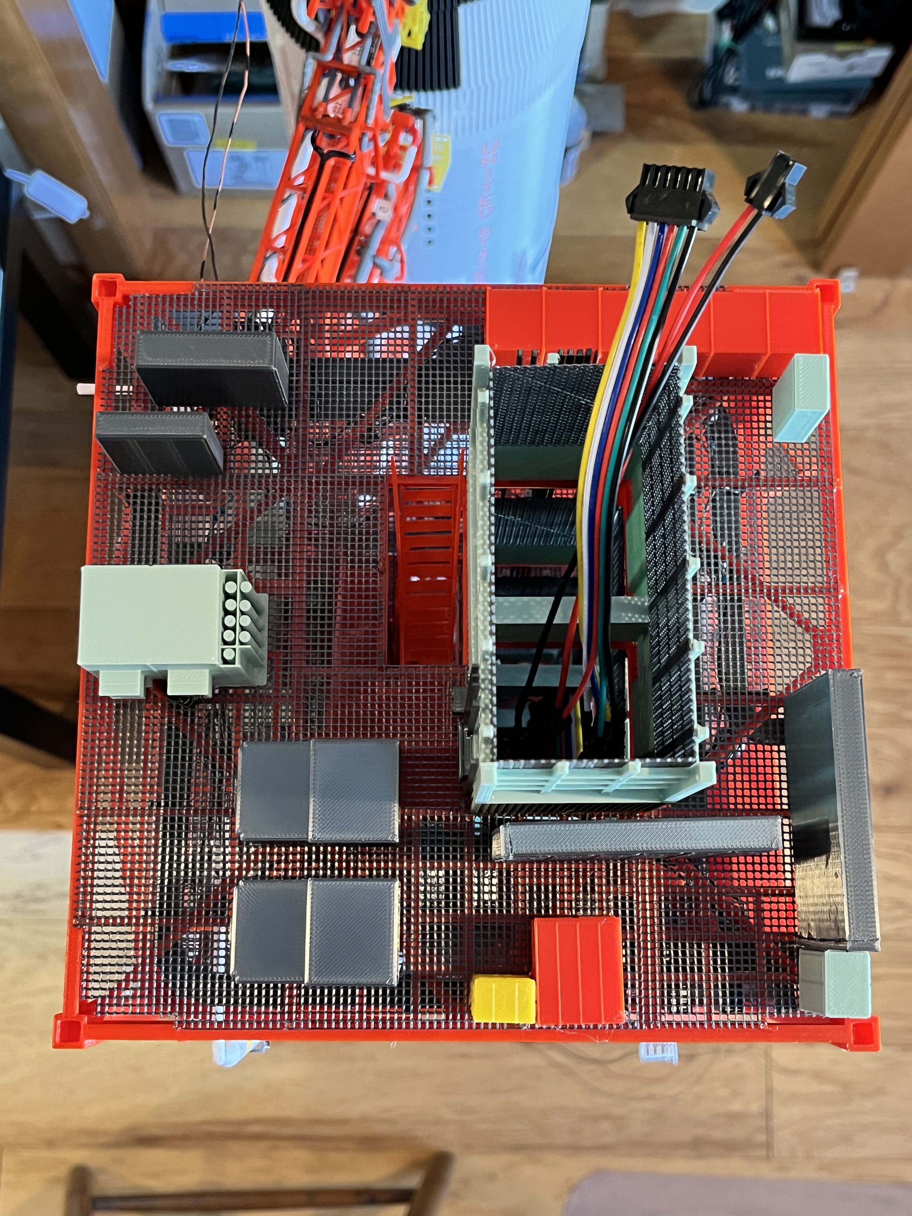
Section 5 Sides 2, 3 & 4 complete: Side 3 is now complete complete, no more pipes higher up. Side 2 has gone from 14 pipes to 7 pipes.


Section 5 Side 1 is now complete and ready for Swing Arm #Z80 Microcomputer System

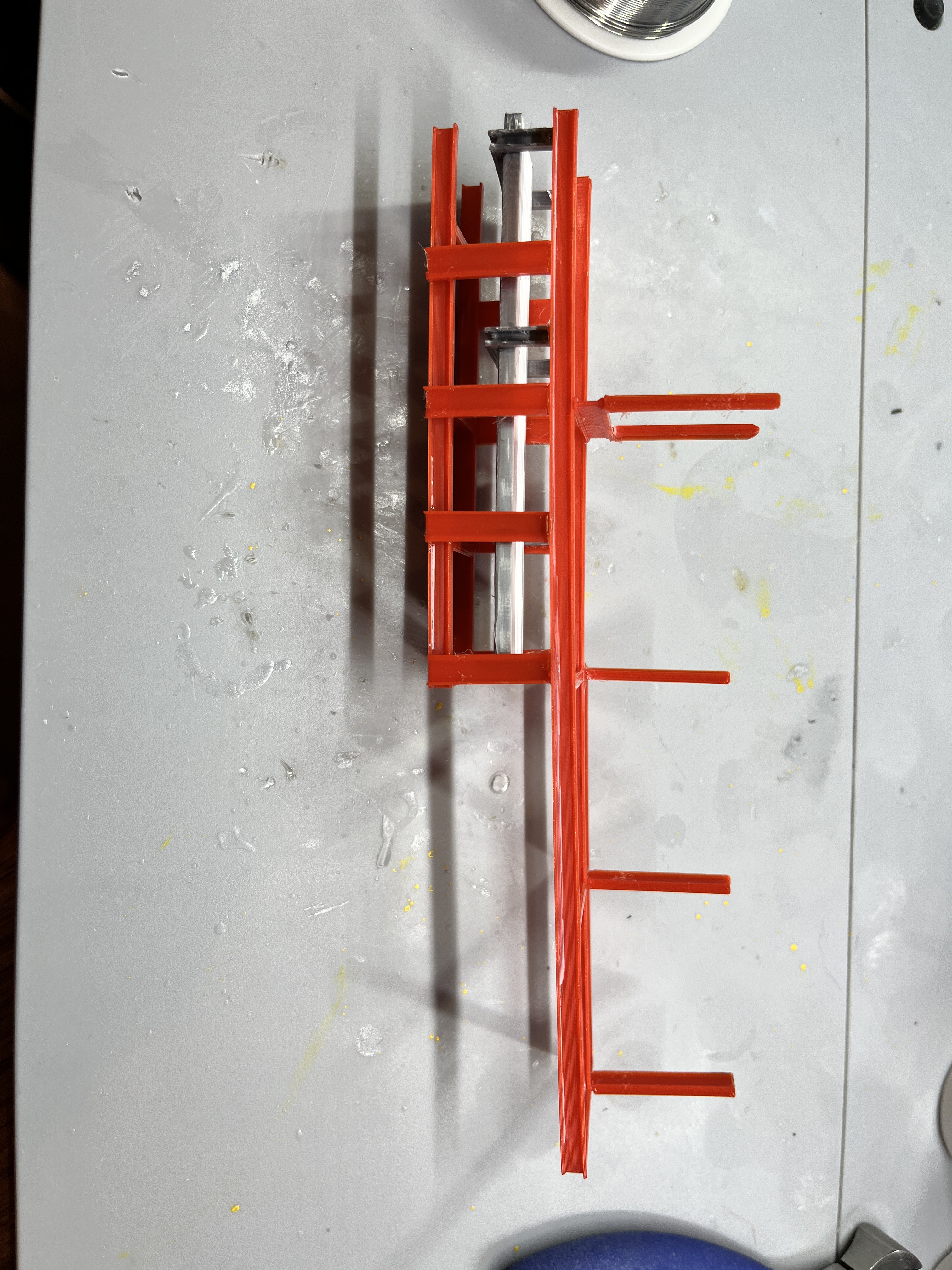
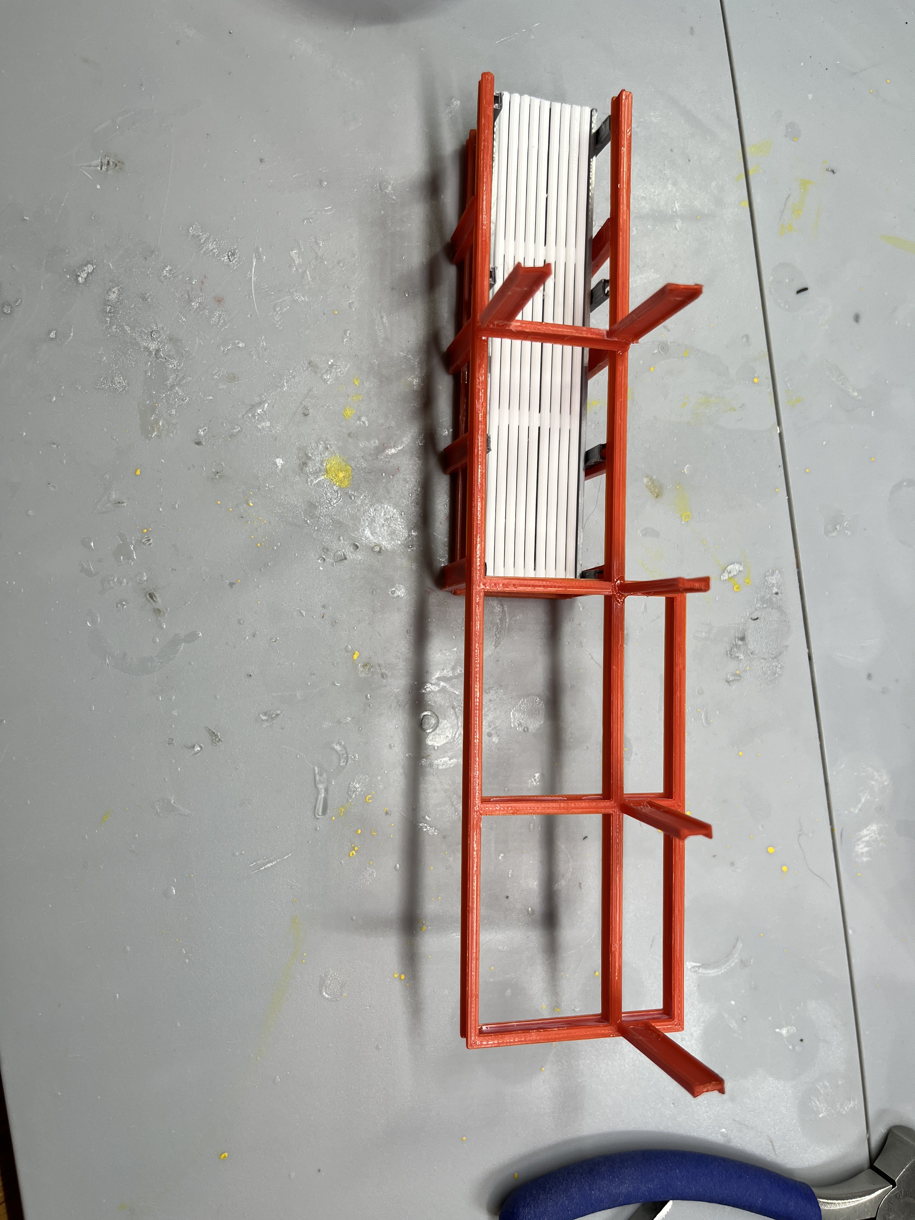
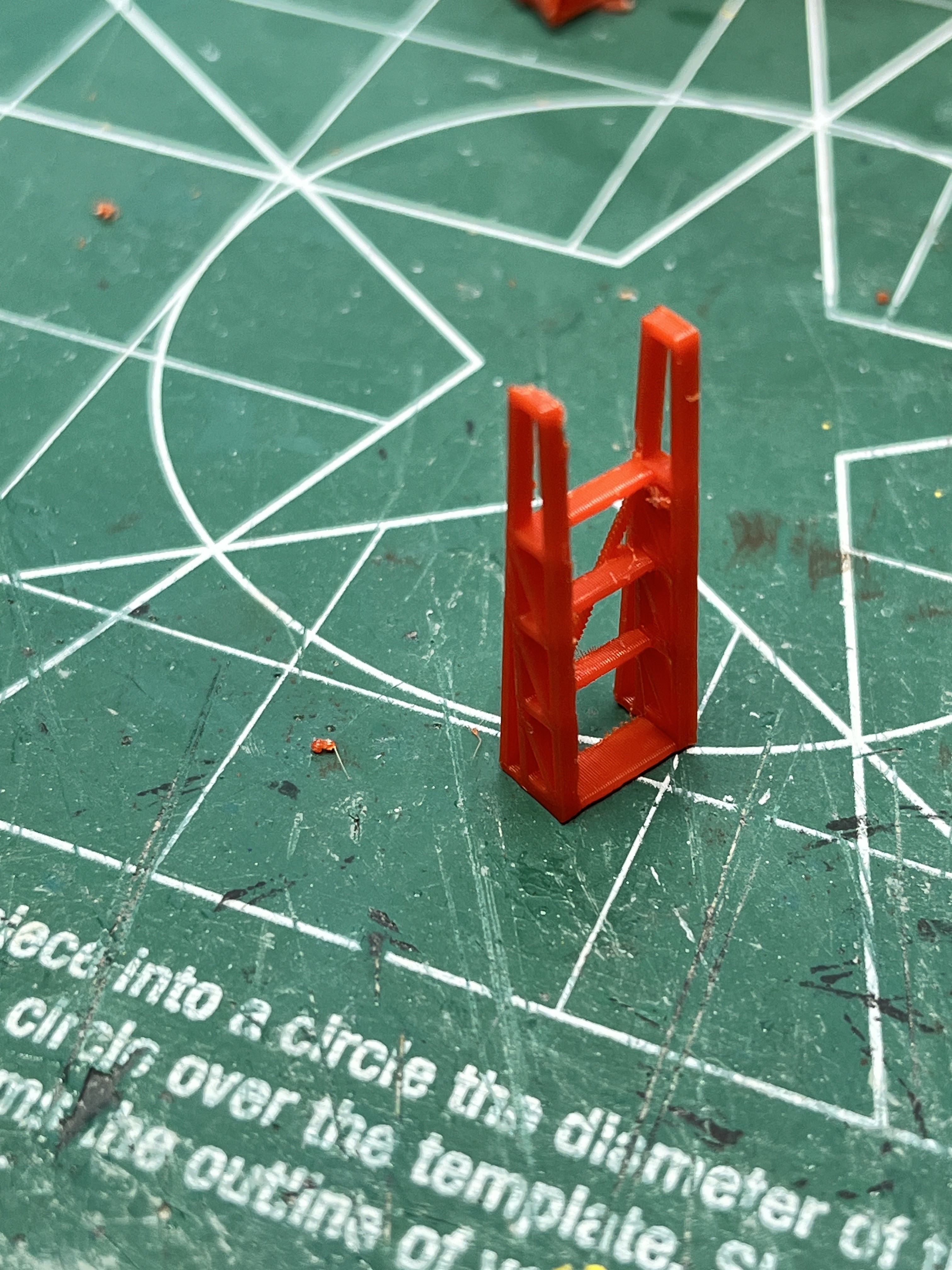
There's always a bit of give and take on the parts, for instance the SA7 ladder to the upper platform. The first design cut was to make the part as accurate as possible. If the part were larger I would have designed it as 7 pieces, but that would be too tedious to assemble. The first print of the part proved to be too delicate. Back in the design tool I beefed up the parts, not necessarily to scale but thick enough to print. Here is the final result. You can see the turbo squid version followed by the failed attempt next to the thicker part which is best printed on its side. I chose to print the exposed side up.
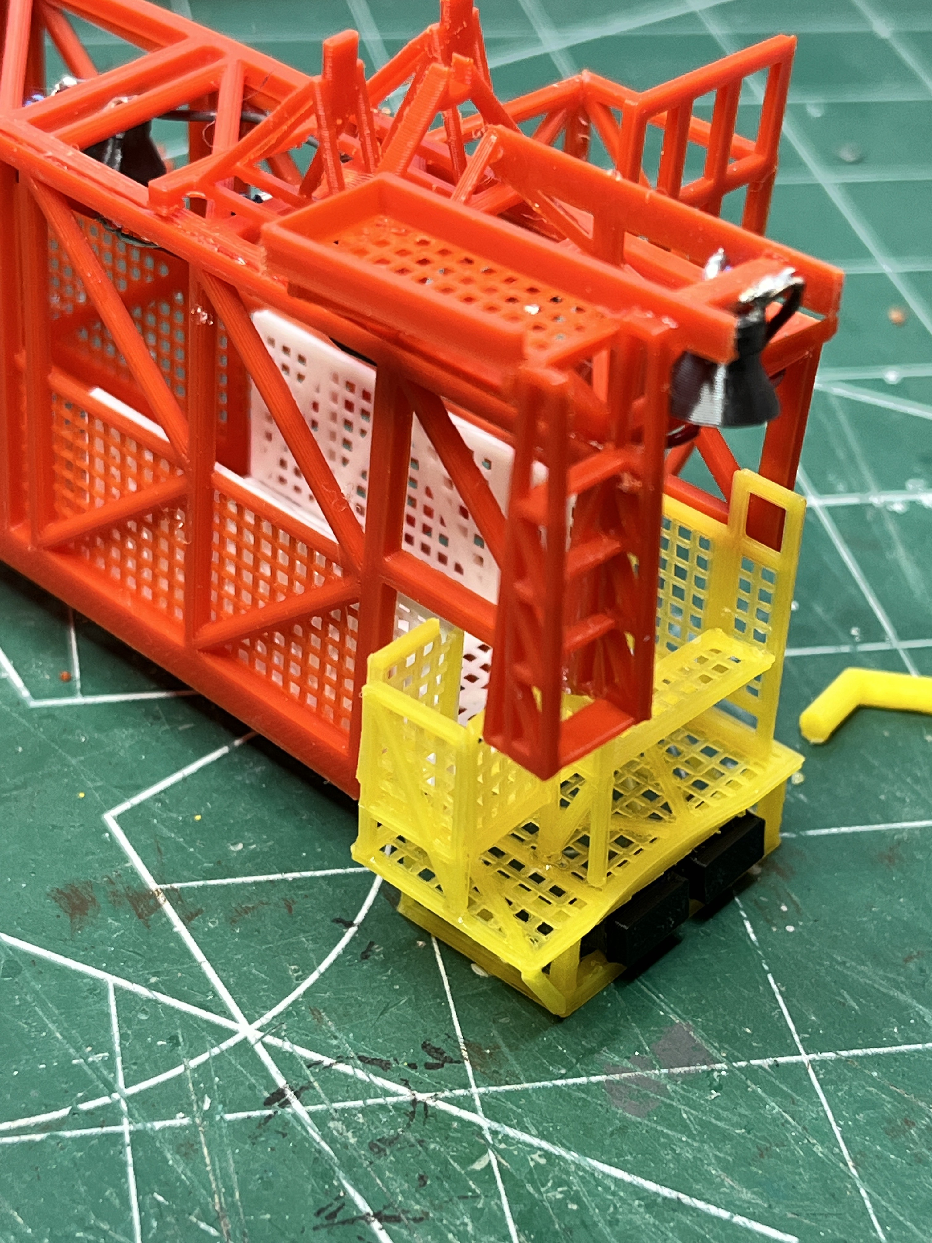
SA7 ready for the pipes. Yet another arm with lots of little details. The white upper platform slides on rails. I chose to glue it in. The main withdrawal mechanism is yet another unique design. I chose to put it in the attached position.
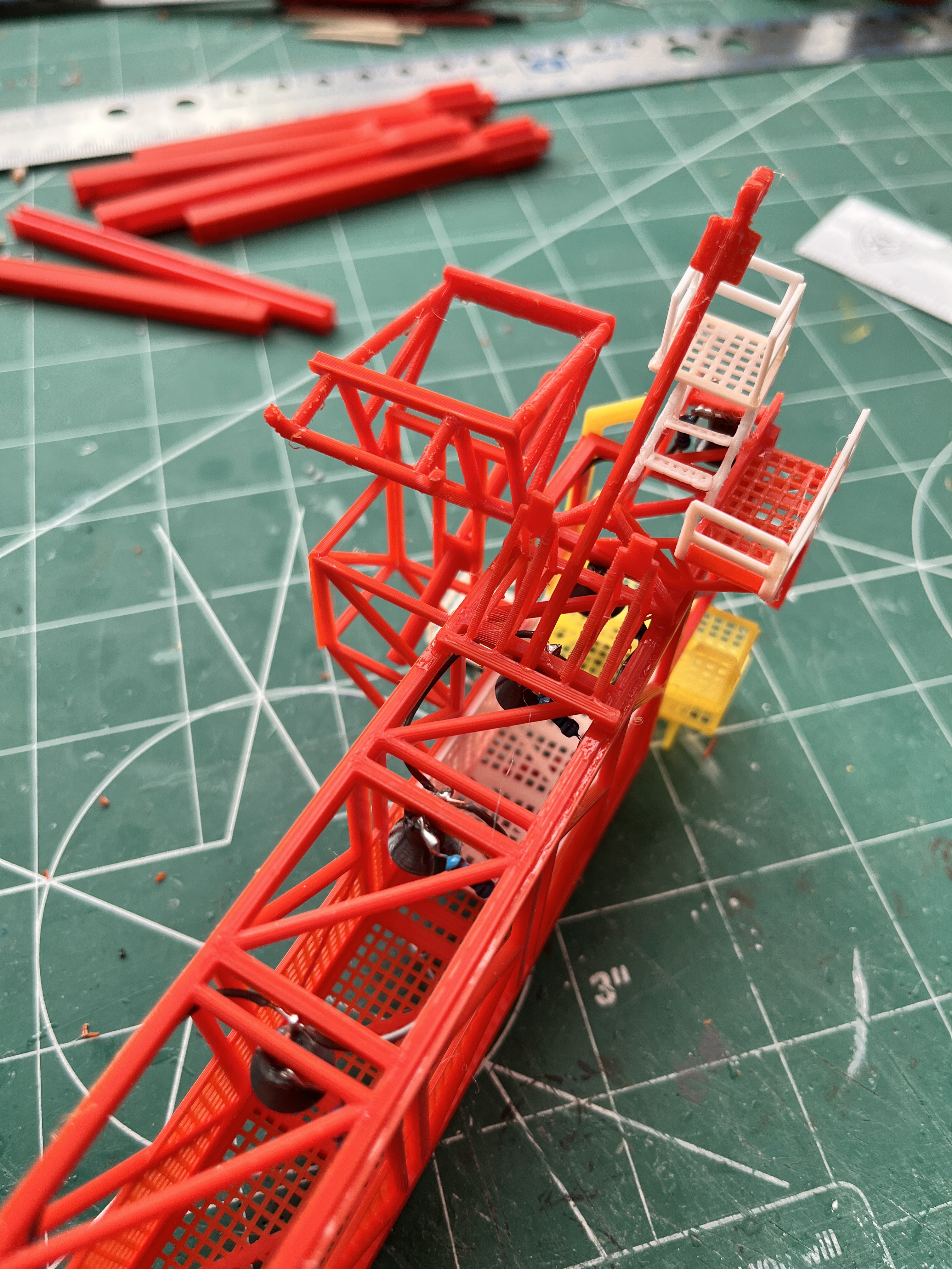

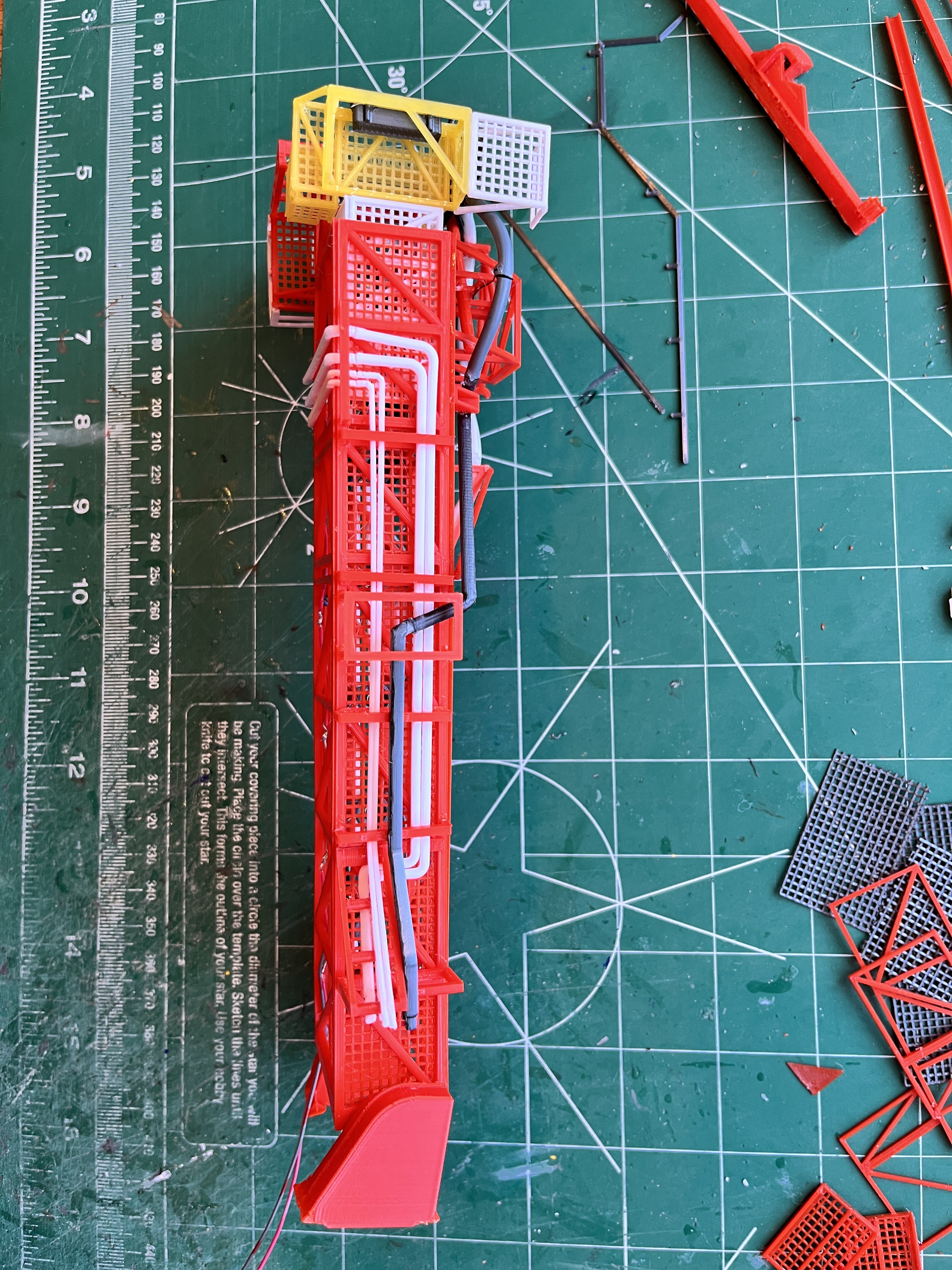
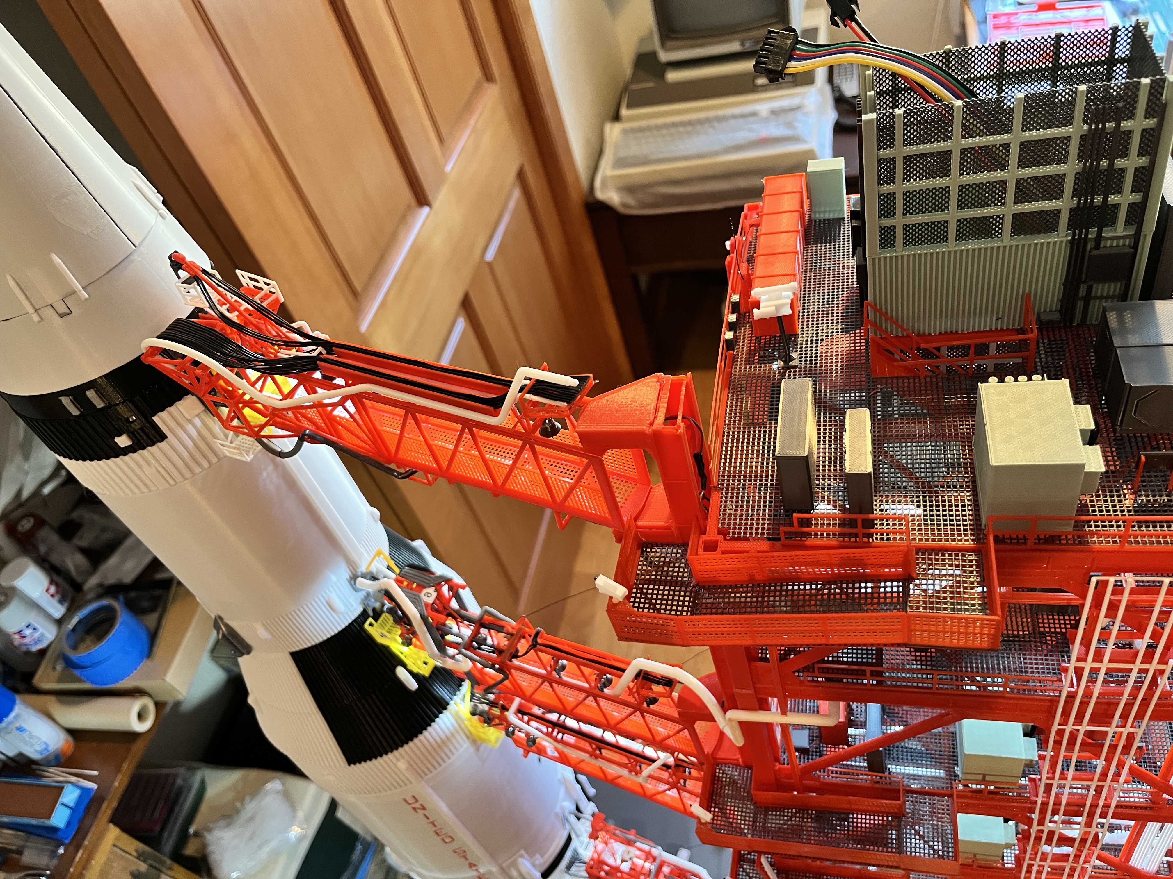
Swing Arm #7 complete and ready to attach. Yet another complicated arm. When I step back and take a look it appears my tower is leaning slightly inward toward the rocket. Each successive arm gets a little more compact, i.e. the movable parts of the arm are not able to extend out as far as they should before contacting the rocket. I am continuing to build the parts the exact dimensions per the plans. I should have been more observant. If you follow in my footsteps check for any lean each level you go up the tower.
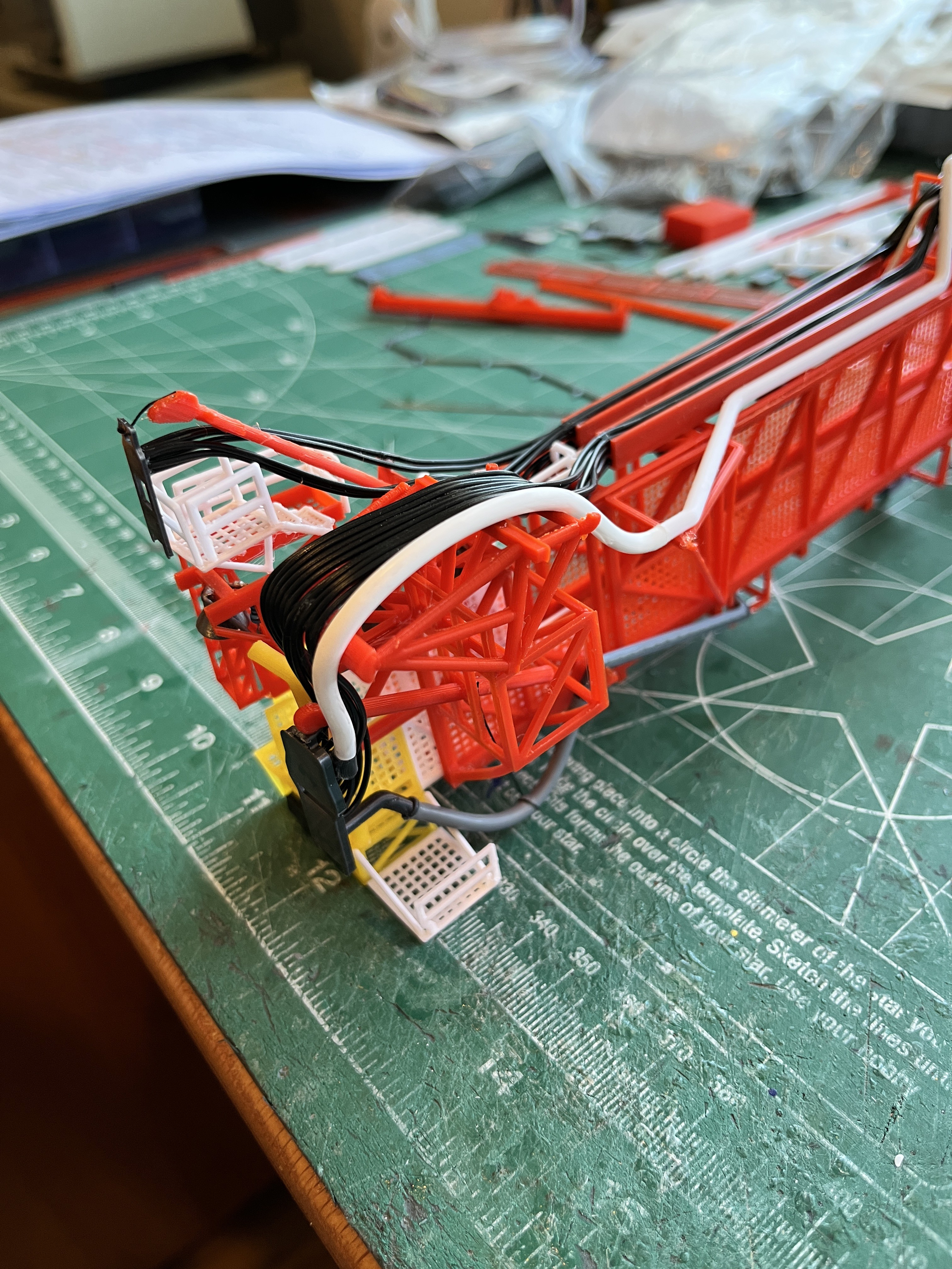
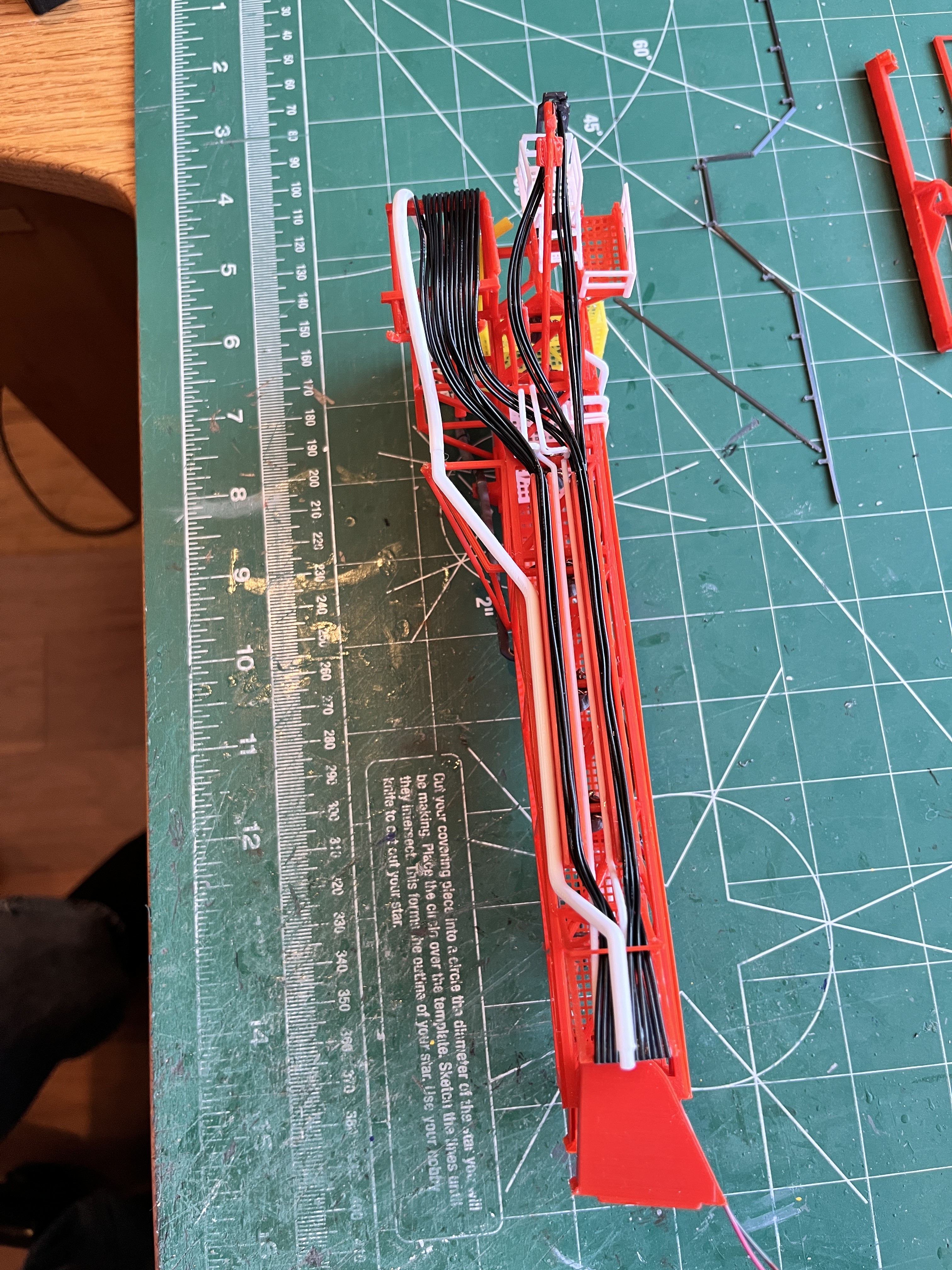
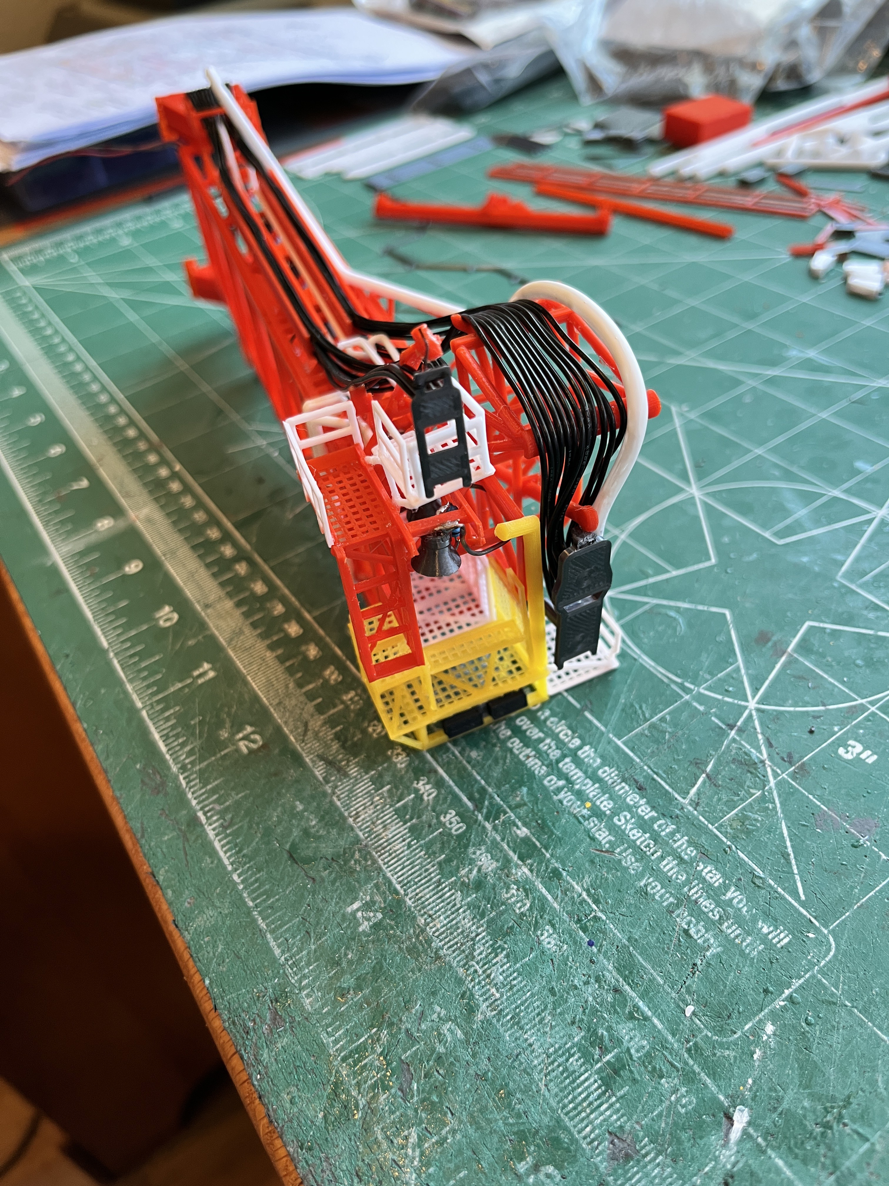
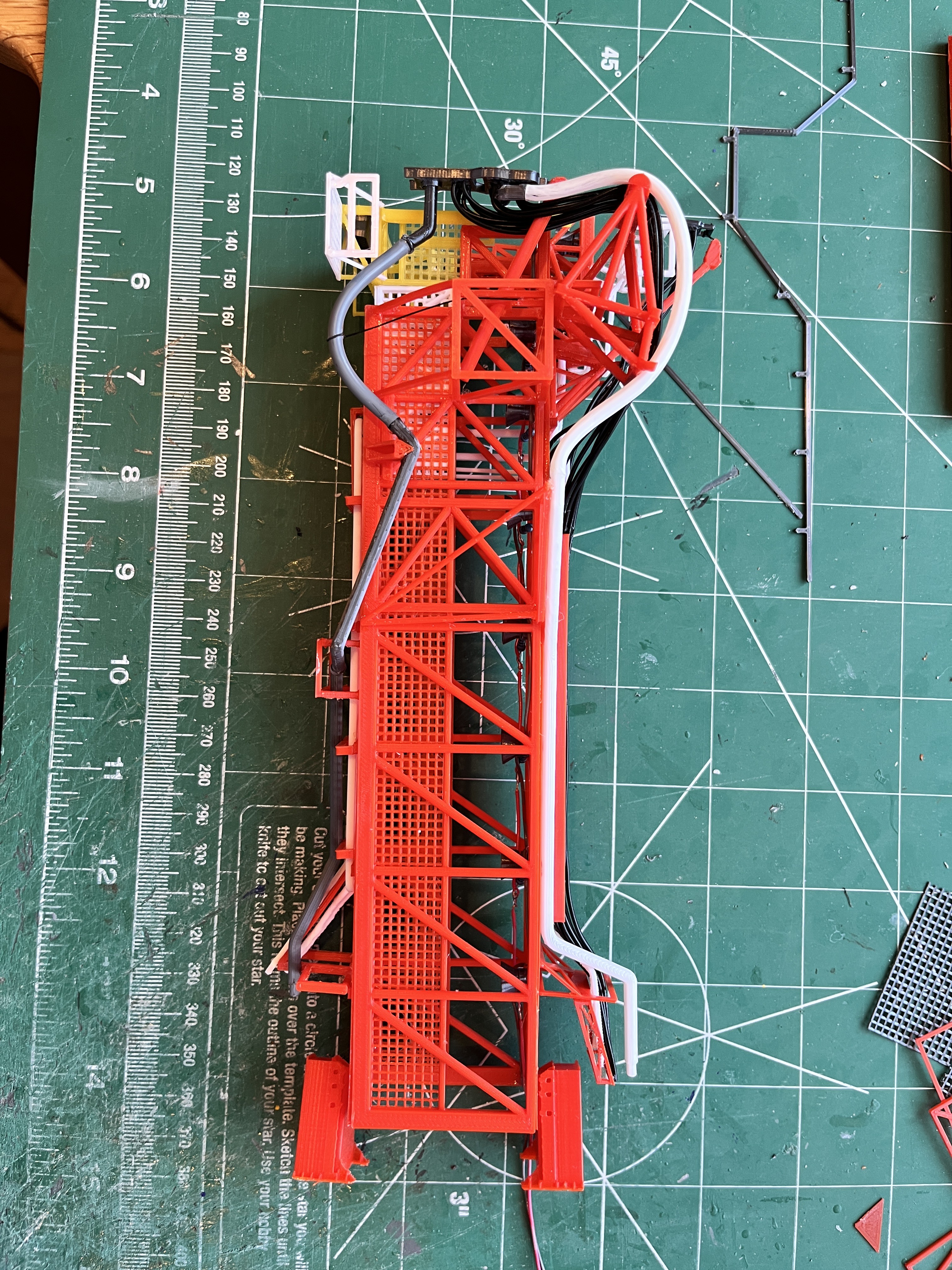
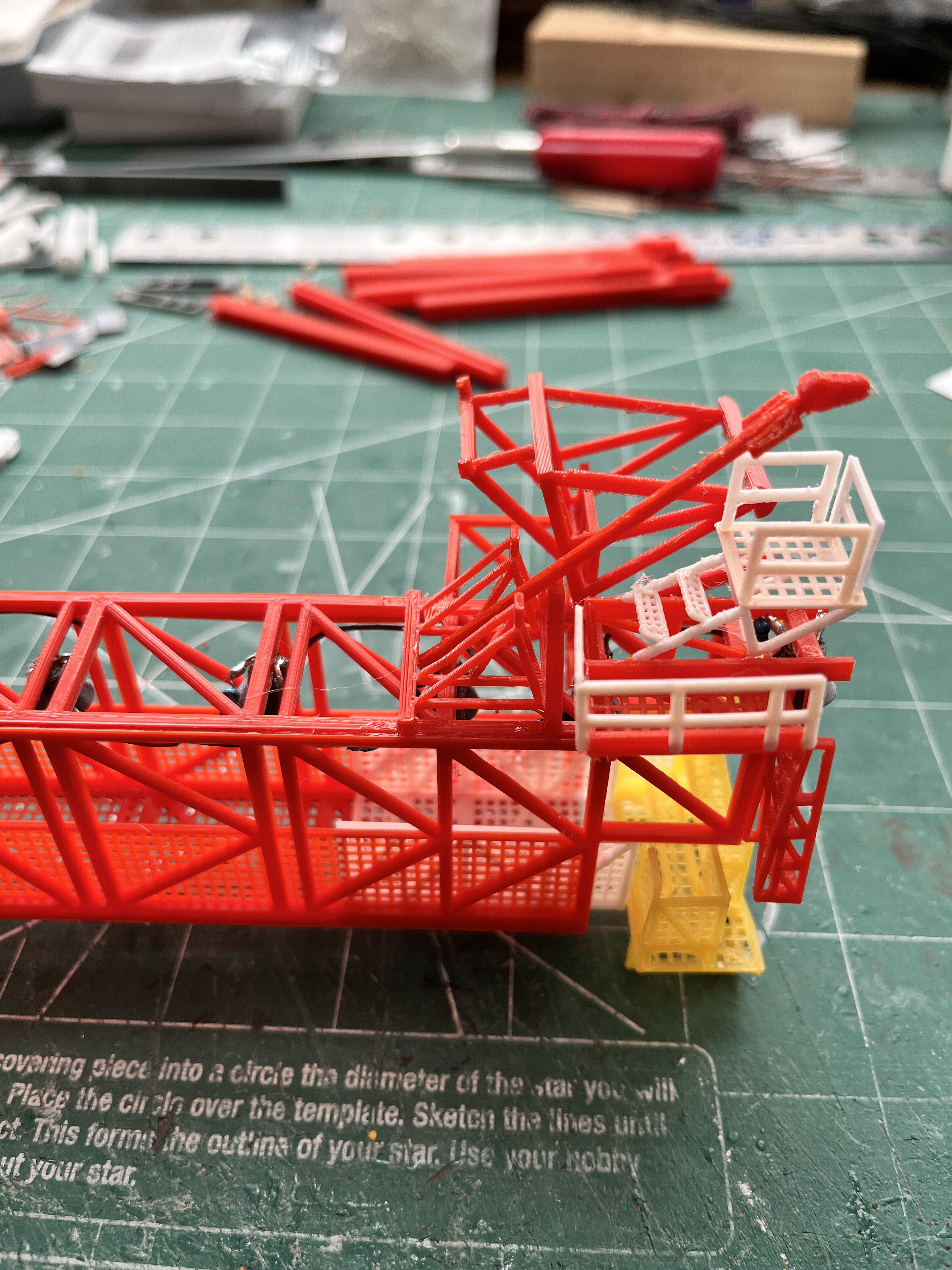
Swing Arm #7 Complete: The rocket can now be fueled. This is the last of the crazy amount of pipes, wires and retract mechanism for a swing arm. This is the first arm that didn't seem to line up with the tower where it should. I mounted the arm so it connected to the rocket where it should. This did make the walkway a simple copy from previous walkways.


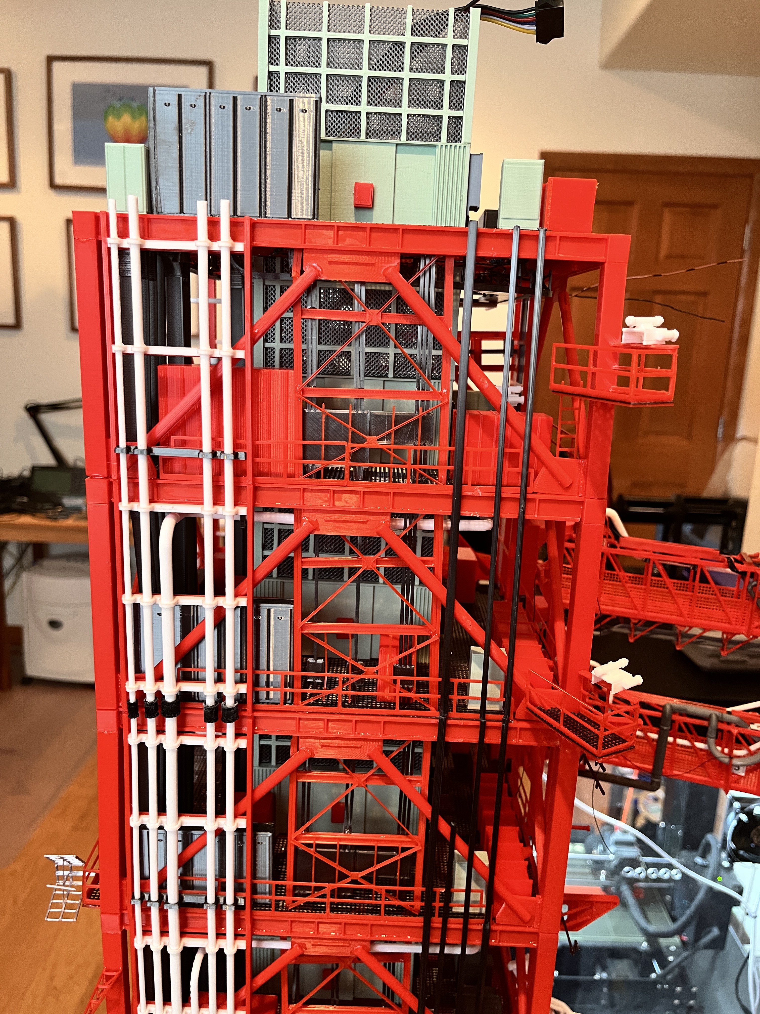
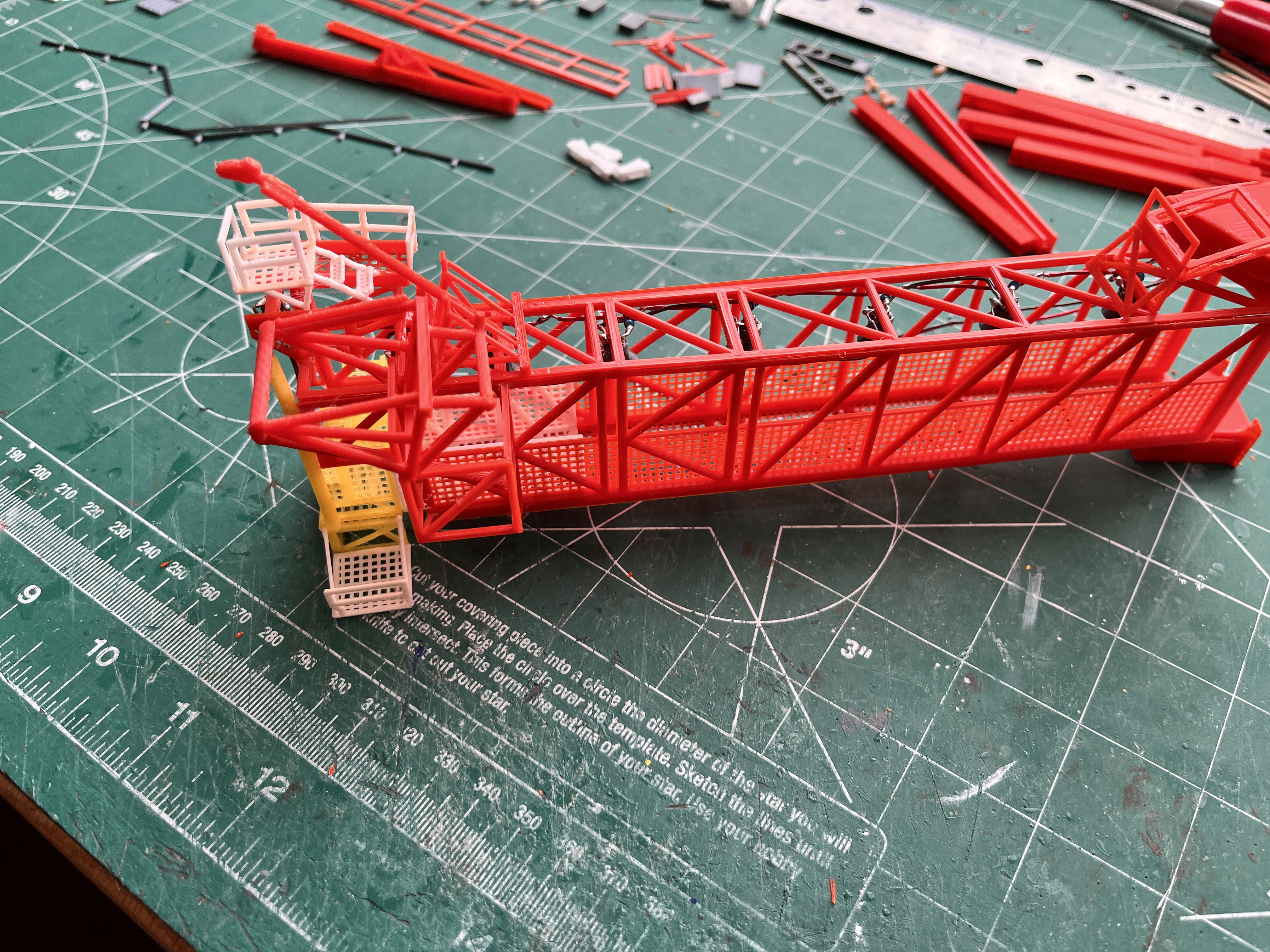
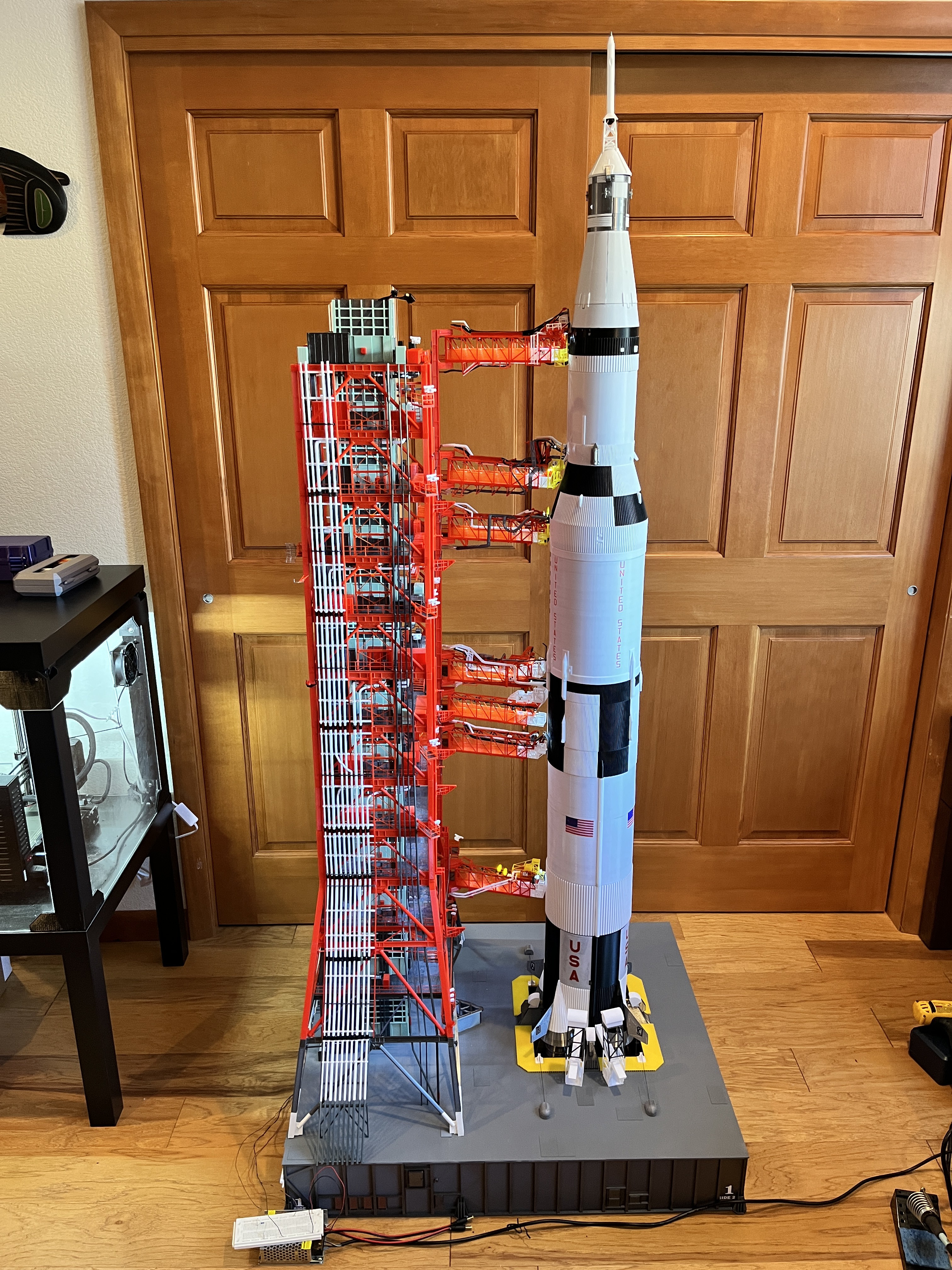
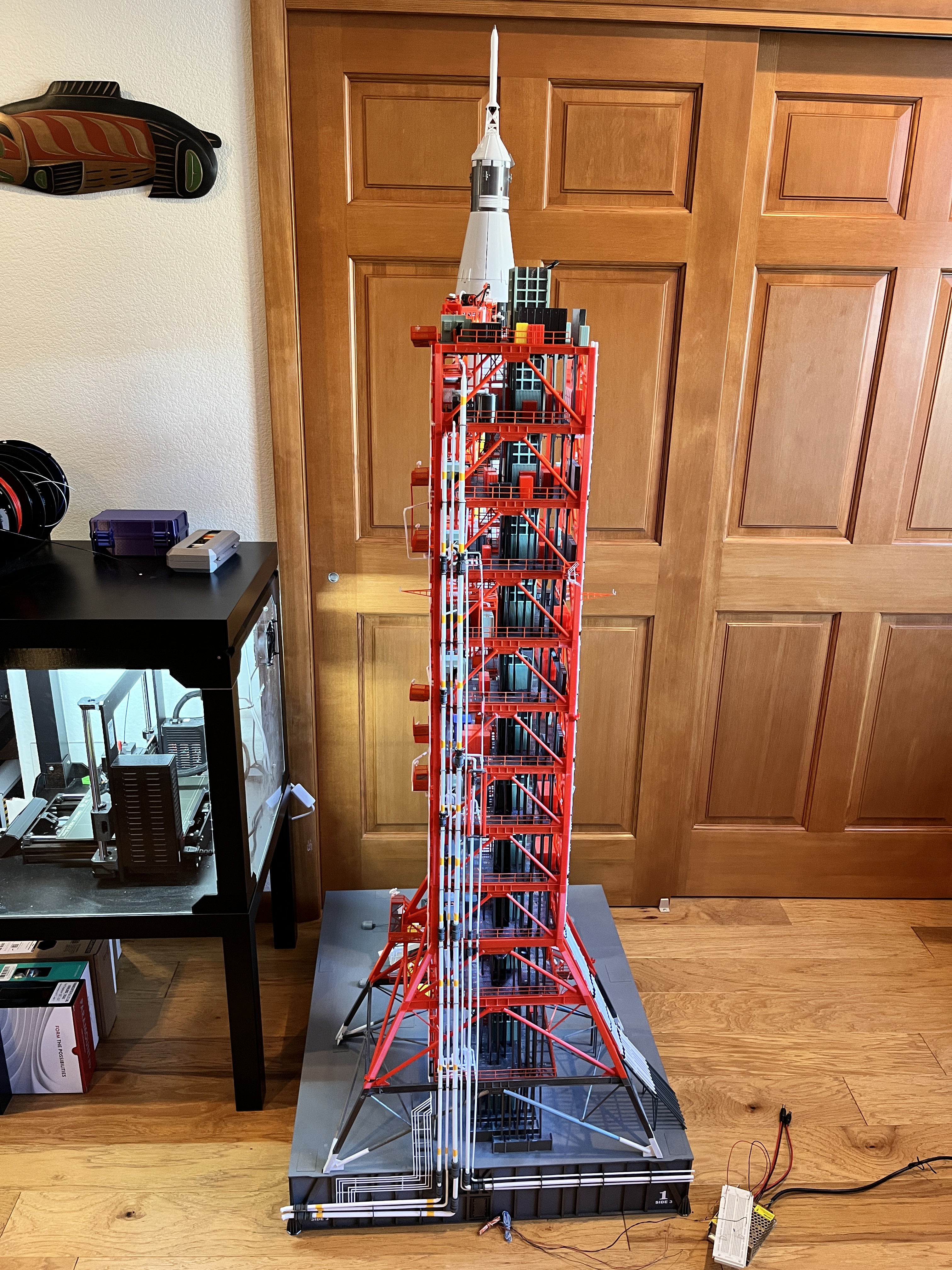
Section #5 Complete: This takes the tower to level 260. The LH2 and LOX pipes are complete. There are only 4 more ECS and 3 water pipes on Side 2. Only 7 cable trays remain.

Discussions
Become a Hackaday.io Member
Create an account to leave a comment. Already have an account? Log In.