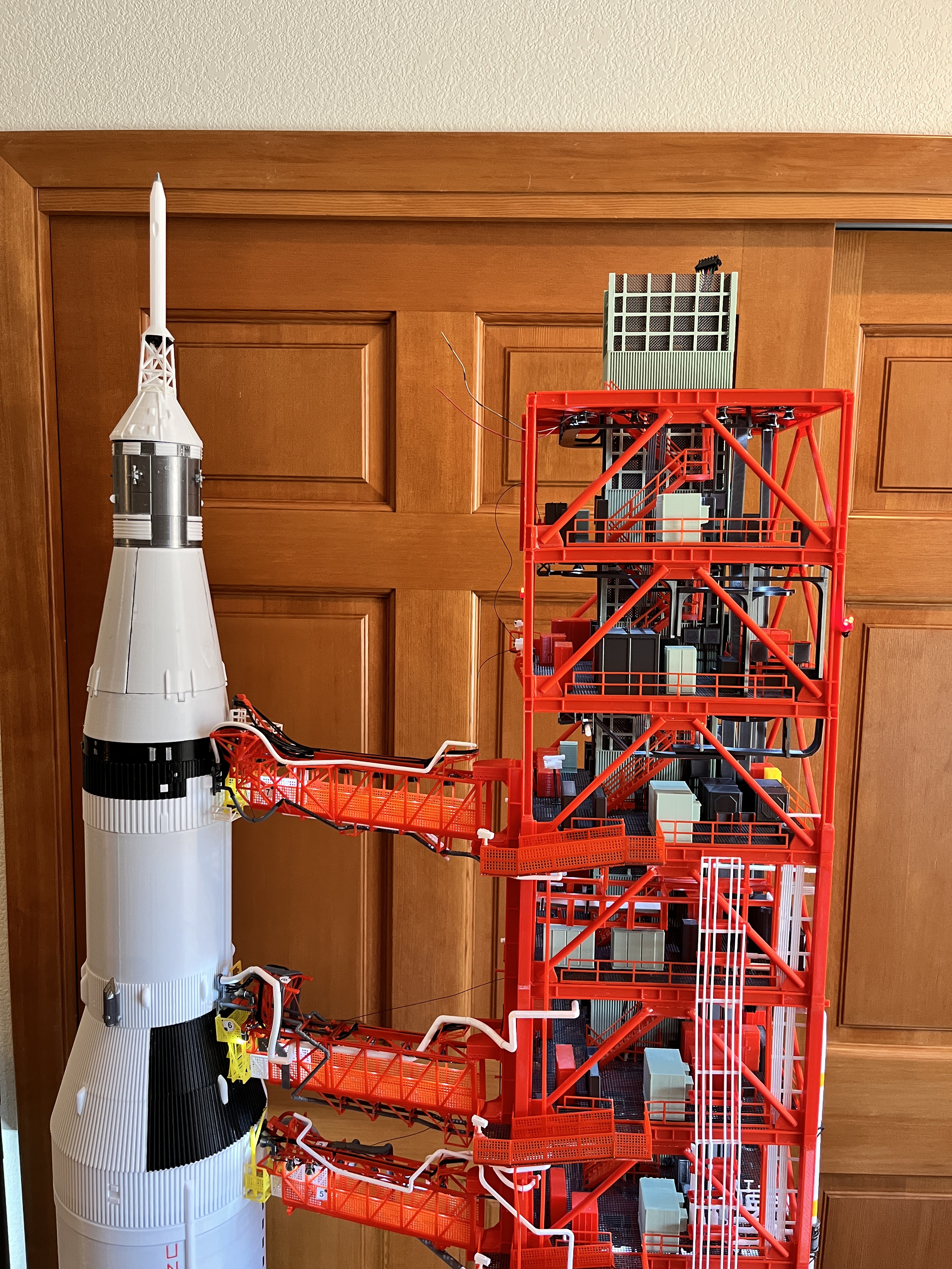
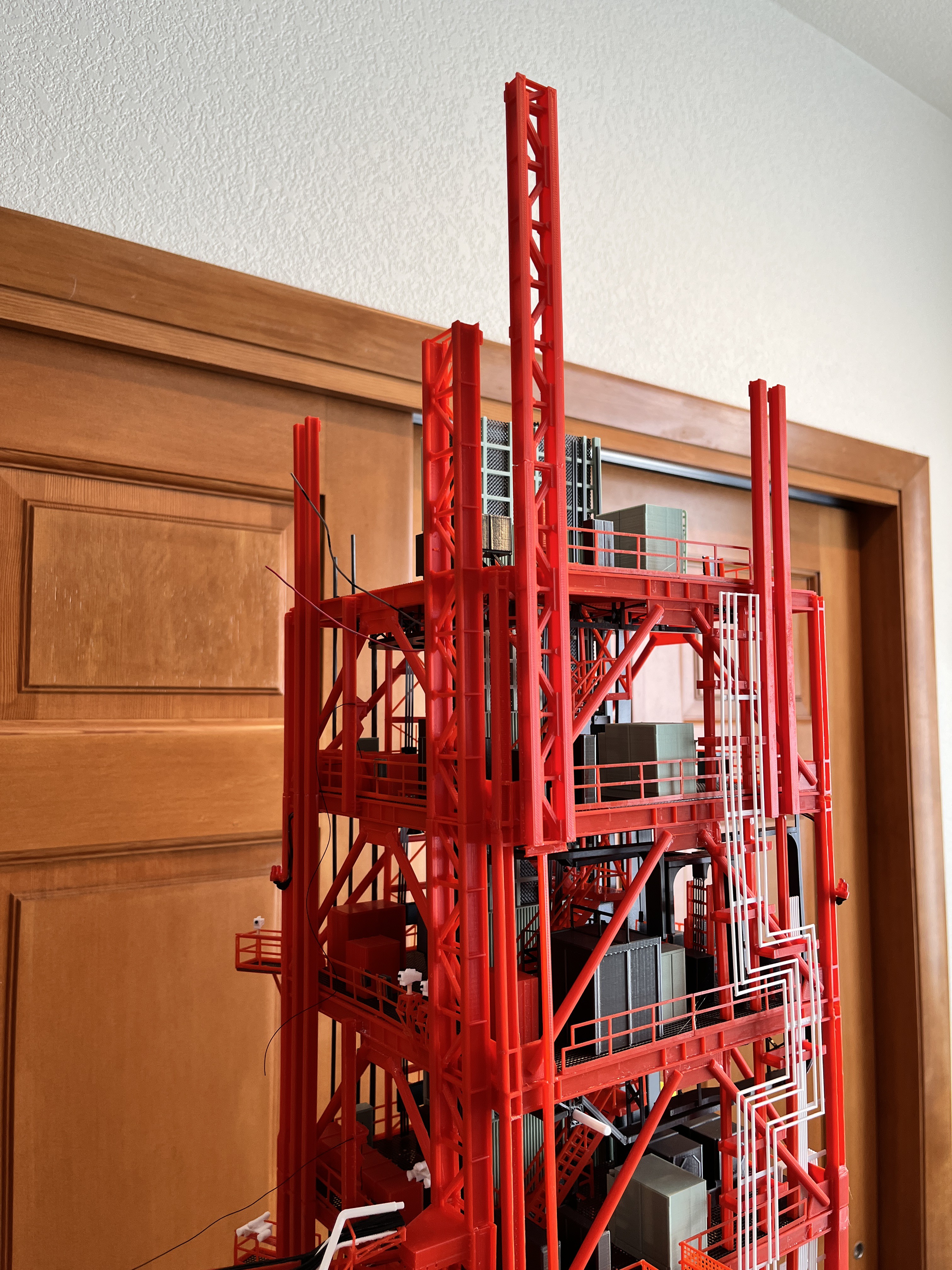
Looking ahead: Only 6 more levels split between two sections remain along with two more swing arms plus the DRRS and of course the crane. The legs and floors from this point on will have to be redesigned to make them lock together better. The vertical braces will be lengthened. The next section will be the last to lock together with square pegs. The last section will be more interesting. I will probably extend the support and locking columns on Side 1 their entire remaining length. There are new support and locking columns on Side 4 to support swing arm #9. These will also be extended up at least one level. This should support the last section on two sides. To continue the build I will need to bring in a step stool to access these higher levels.
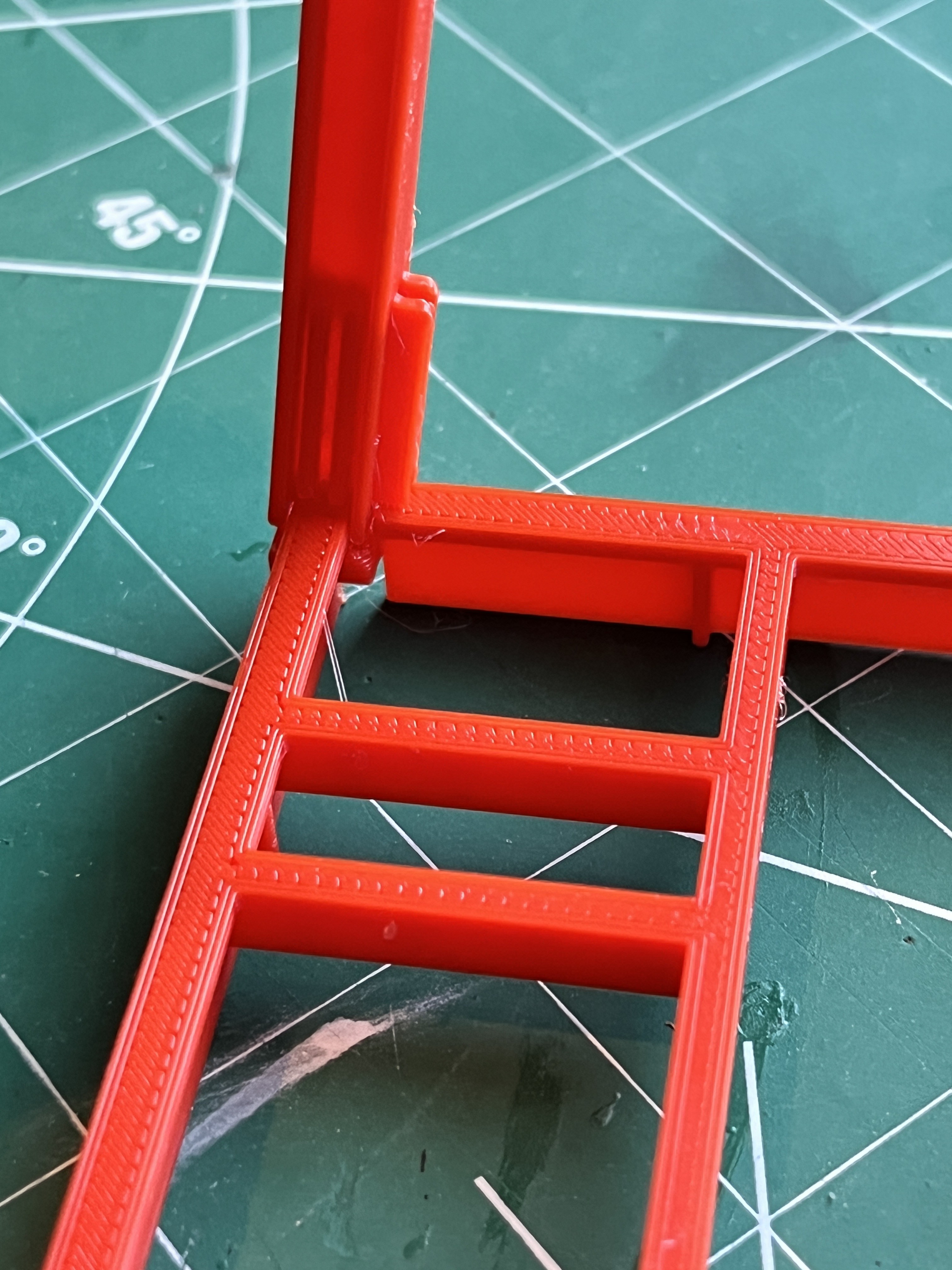
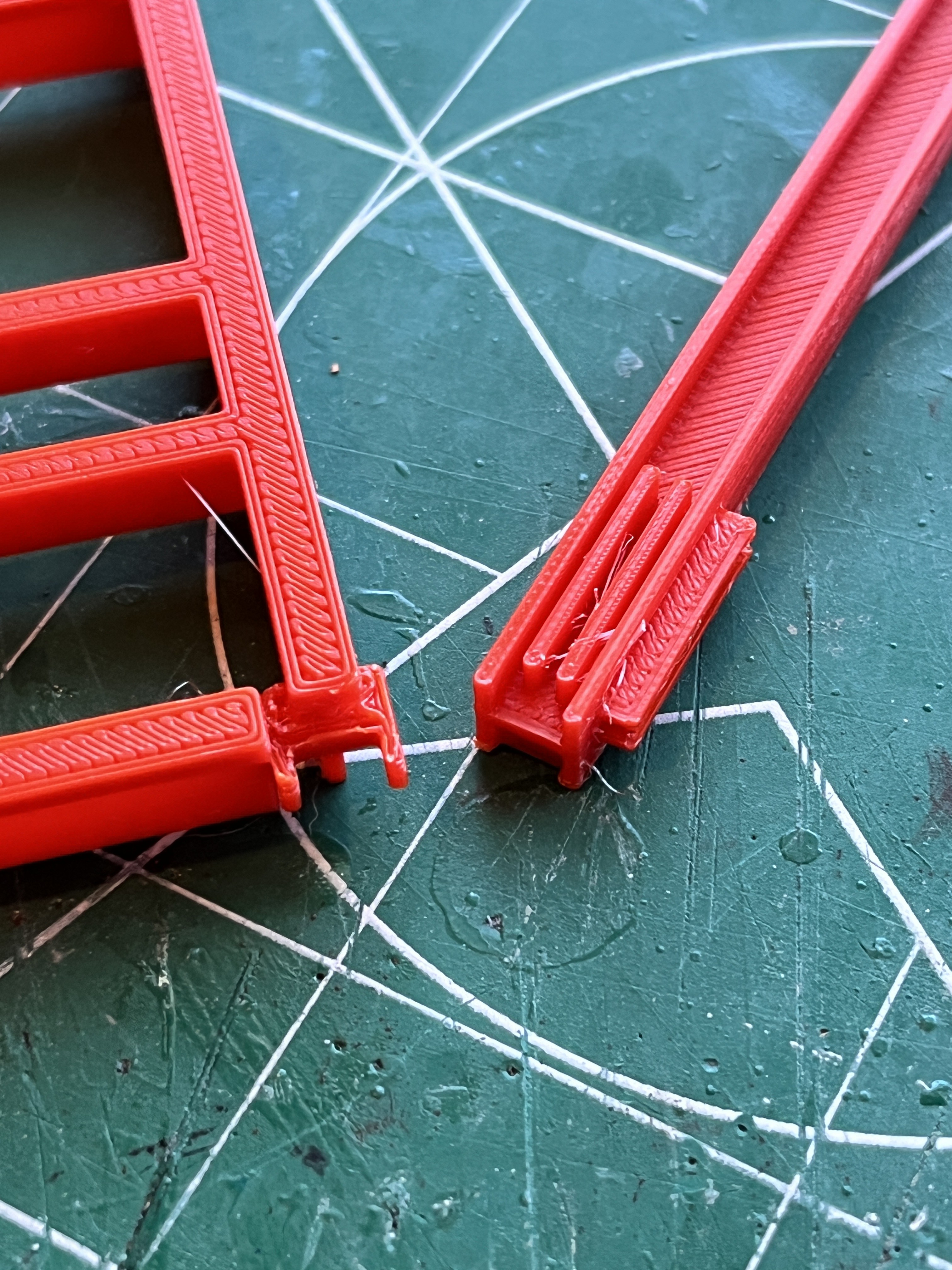
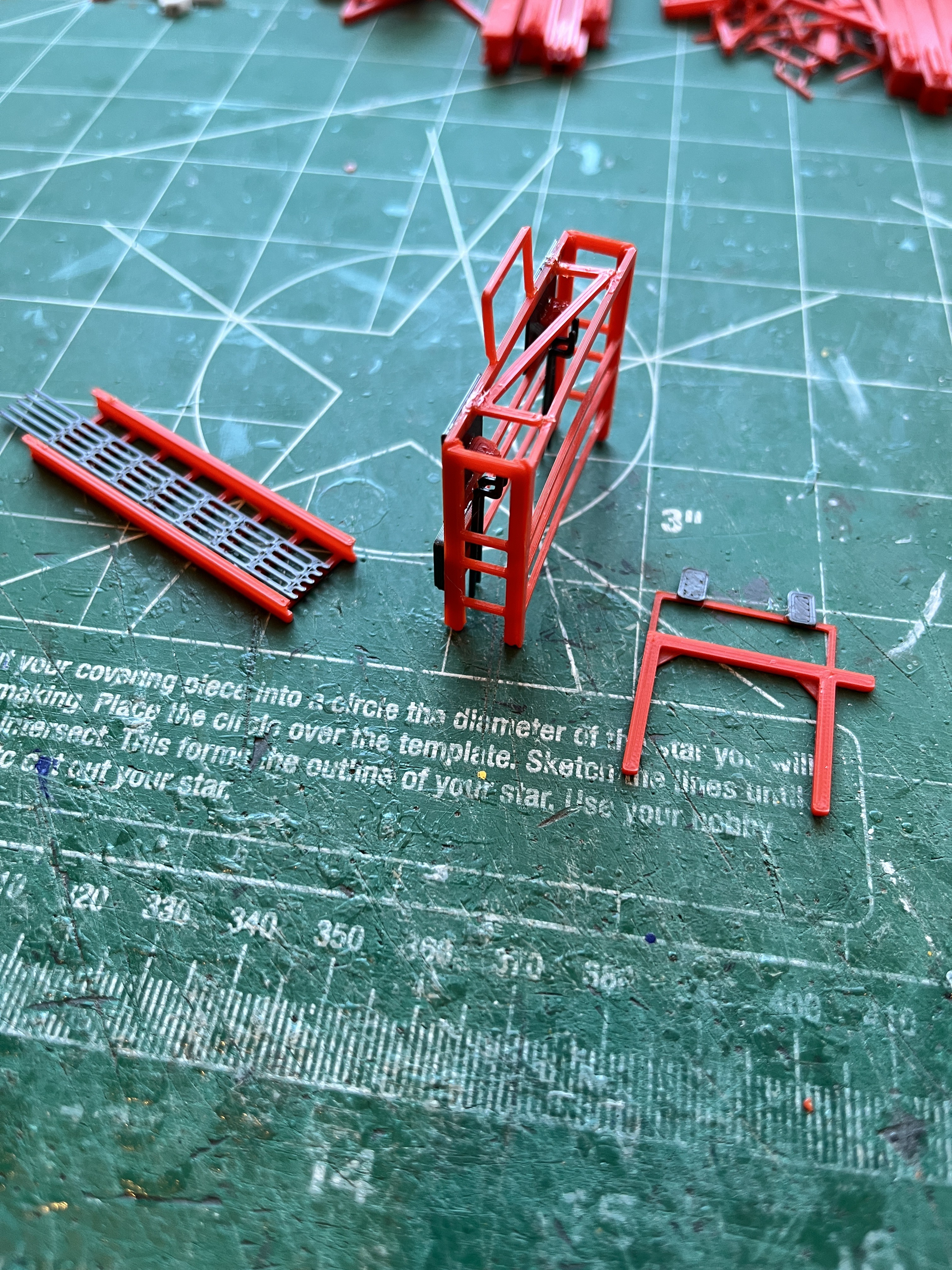
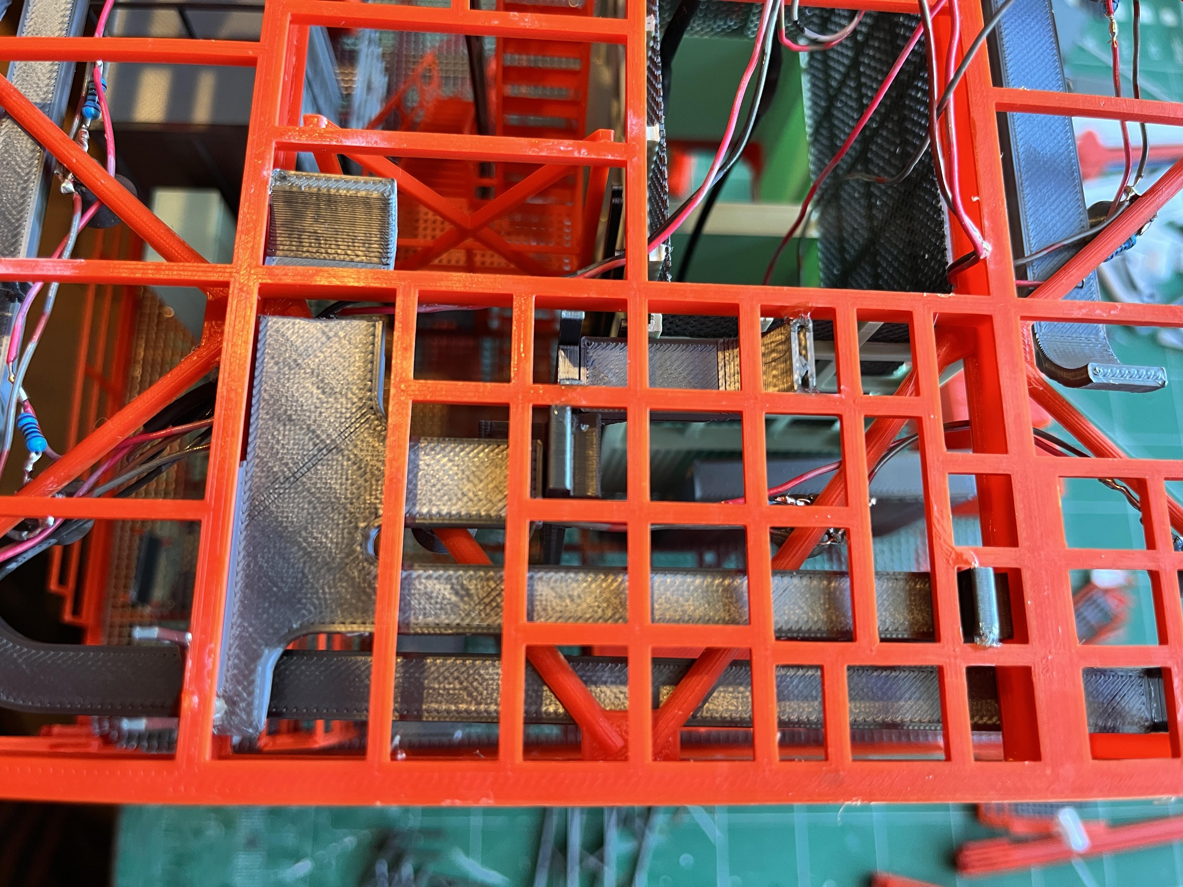
The higher up legs and floor beams have been redesigned so the legs set down into the floor beams. This alone will work well for the glue joints but my worry is the removable joints between Sections 6 and 7. The legs are getting awfully spindly. The Columns Decoded spreadsheet shows these legs are 6.6 x 6.6mm with the next level being 6.2 x 6.2mm and the last two legs are 5.9 x 4.2mm. For this last section joint I plan to add small square pieces that are glued to the top of L320 just behind the 12" cross braces. You can see where these will go in the picture below. I places a pair of silver filament pieces where they will go. These will help stabilize the joints. For additional support, on Side 1 the support and locking columns end at L340 so I will extend these up from Section 6. On Side 4 there are support and locking columns for SA9. The locking columns go from L300 to L340 and the support column goes from L300 to L360. I plan to add the locking columns and support column to Section 6. These additions should solidly anchor Section 7. Since the DRRS attaches to the Side 1 support column (Section 6) and the Side1/2 leg (Section 7) I will have to make this part removable.

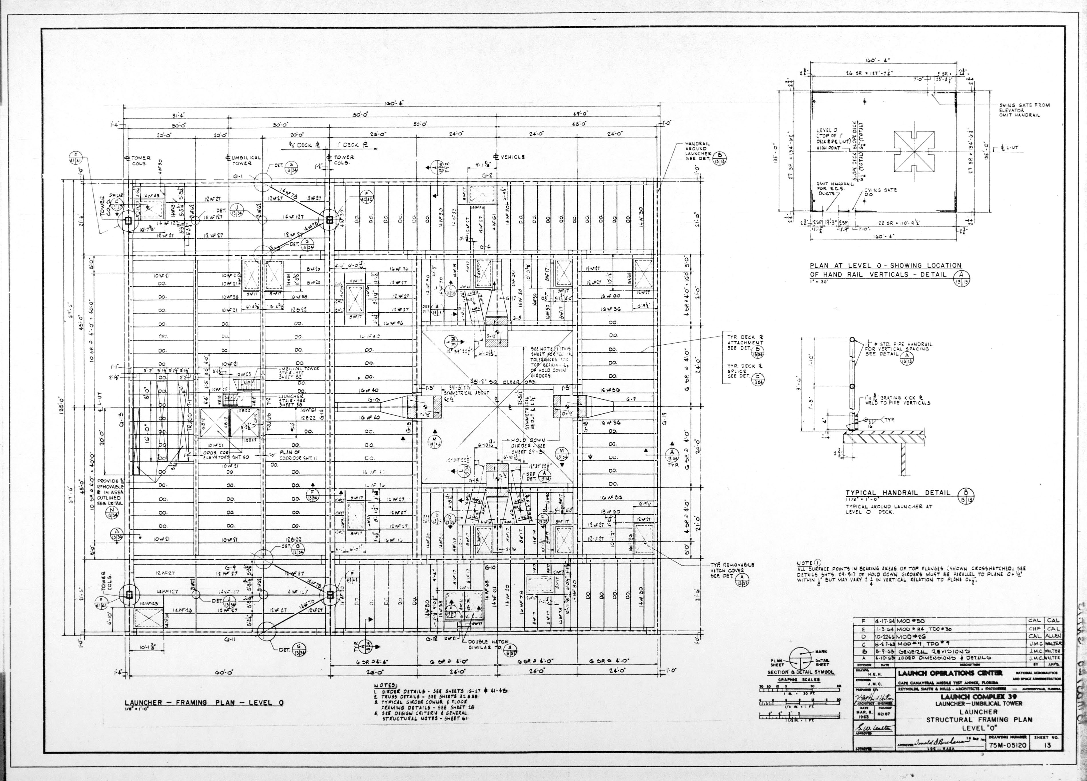
Snow Eagle, I used the drawing 75M-05120-013. The overall dimensions of your model should be pretty accurate so base your measurements off of known locations (i.e. the outer edges and engine chamber). Sometimes I have had problems reading some of the measurements so what I do is I have a 6-sided engineering ruler with six different scales divided into 1/10ths. What I do is scale up the drawing on the screen so a known measurement is exact for one of the scales. I then use that scale to measure the unknown measurement. It is not alway exact but it is better than nothing. Here is an example... Your model is looking great! Hope this helps.


Snow Eagle,
Another thought on hatch placement. After laying out the hatches down to the millimeter, before gluing them on, compare the location visually with drawing 75M-05120-012. Measure and pencil in where the tower legs will go along with the elevator. Do the hatches align with each other and with other objects on Level 0? This is probably more important than the exact millimeter location of the hatches.
The location of the tower legs is much more important to get accurate. Verify the side 1 leg locations line up with the Fixed Support Interfaces per drawing 75M-05120-015 and visually with the actual Fixed Support Interfaces on the side of your model. If the legs don't line up perfectly with the Fixed Support Interfaces, that's all right, just make sure the tower leg locations are exact. All the swing arms will depend on how exact you make the tower location in relation to the engine chamber. The center of the side 1 tower legs should be exactly 50' 0" (254mm at 1/60 scale) to the center of the engine chamber and the engine chamber should be centered on the side 1 tower legs. You may find other measurements off slightly but make sure you nail this measurement. If your engine chamber is off slightly I would shim and modify it before adding the inner chamber panels. You should probably go ahead and cut in the square holes for the tower legs, verify and fix any engine chamber location imperfections before you paint the level 0 surface.
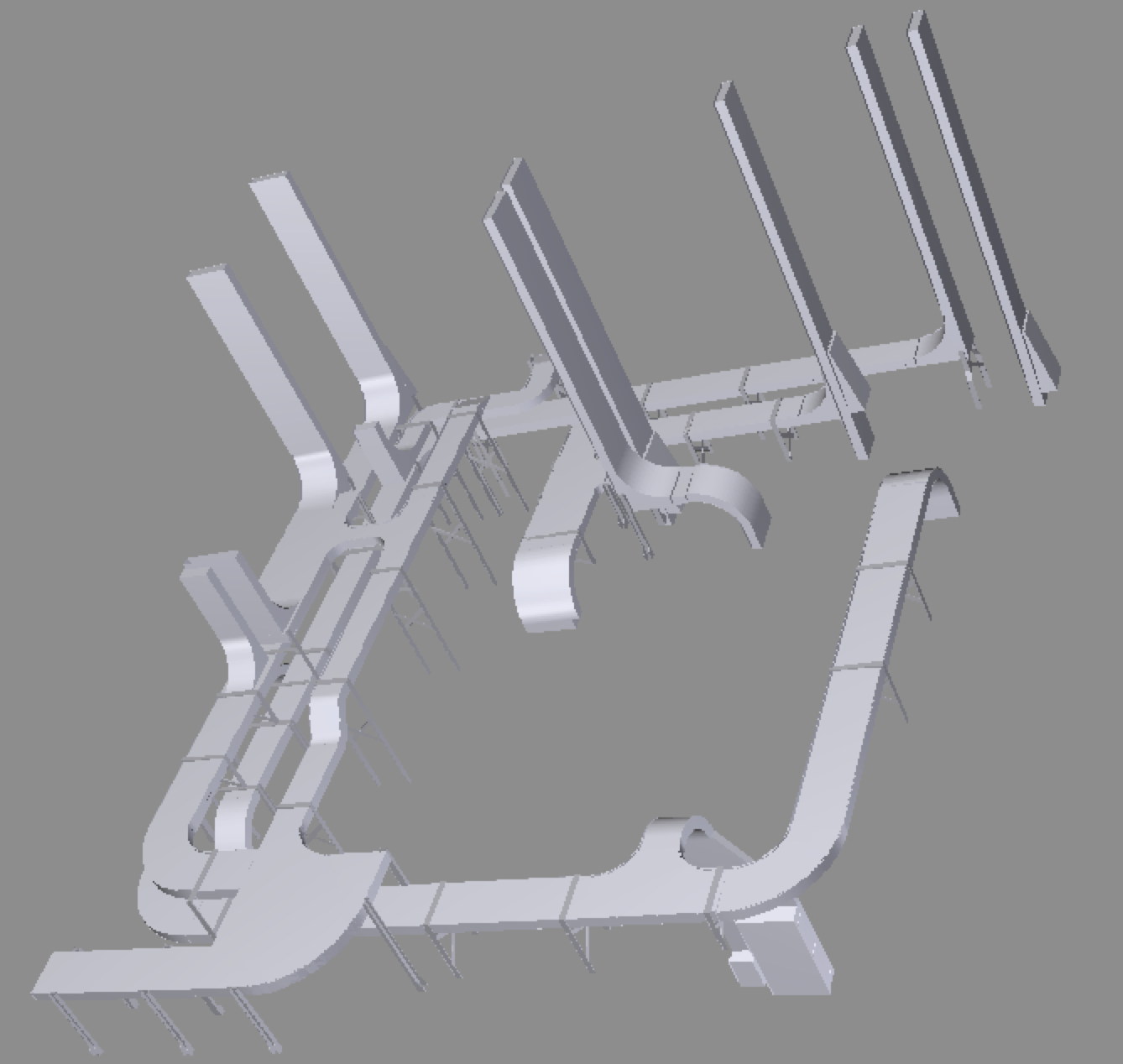
The image below shows some of the measurements I used to construct Swing Arm #1. Most of these measurements won't apply until you get up to that point on the tower. When I got to that point I measured and I was exact with the angle and off by a millimeter or two on the length. This will be your first check point on how well you did with the tower to rocket measurements.

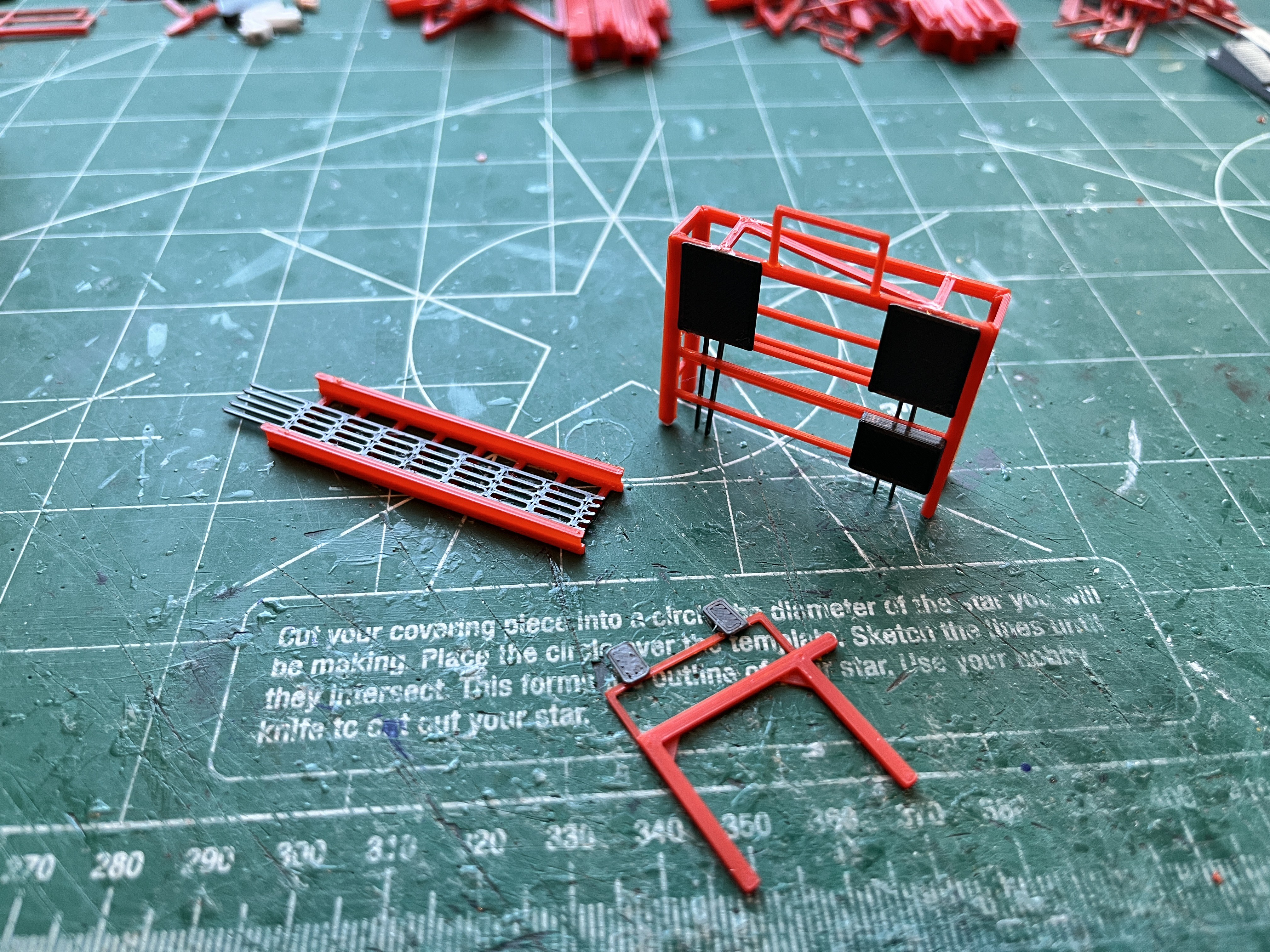
I keep thinking the levels are going to get easier the higher up you go. Not true. The next few levels are packed with equipment and overhead cable trays. Here are few missing parts for L280. There is a vertical cable tray to support the cables coming down from an overhead cable tray. The part is small enough that I angled the I-beam flange to webbing joints so it can be printed as one piece without supports. The Trim Control Unit rack is a bit more complex. There are 15 parts to this rack. And then there is an electrical power distribution rack with two grey doodads on top. It was either doodads or thingamajigs and they looked more like doodads so that's what I went with.
Its kind of hard photographing the underfloor cable trays that hang from L280. I probably should have taken this section off and turned it over. I did have to modify two of the trays to get them correct. For the next level I will definitely have to get out the step stool.
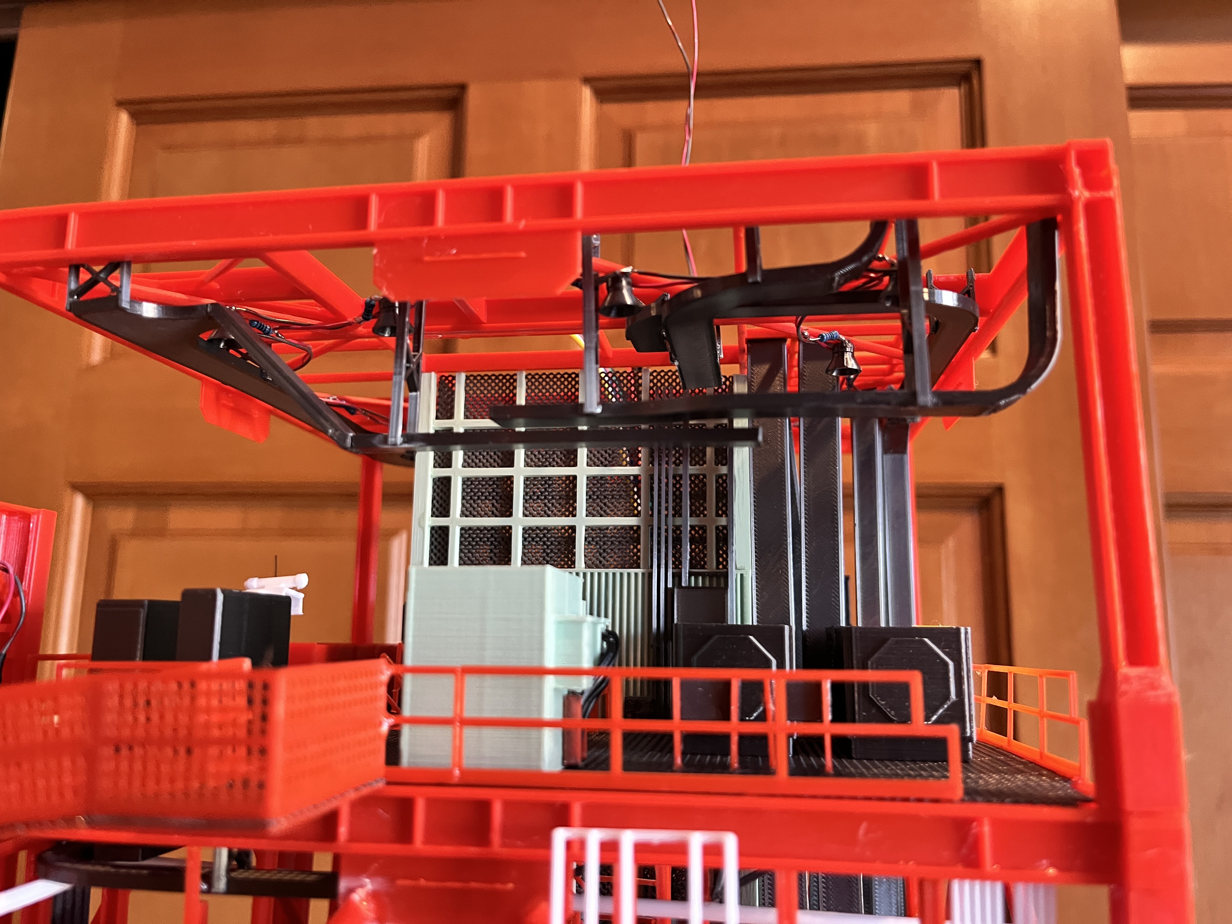
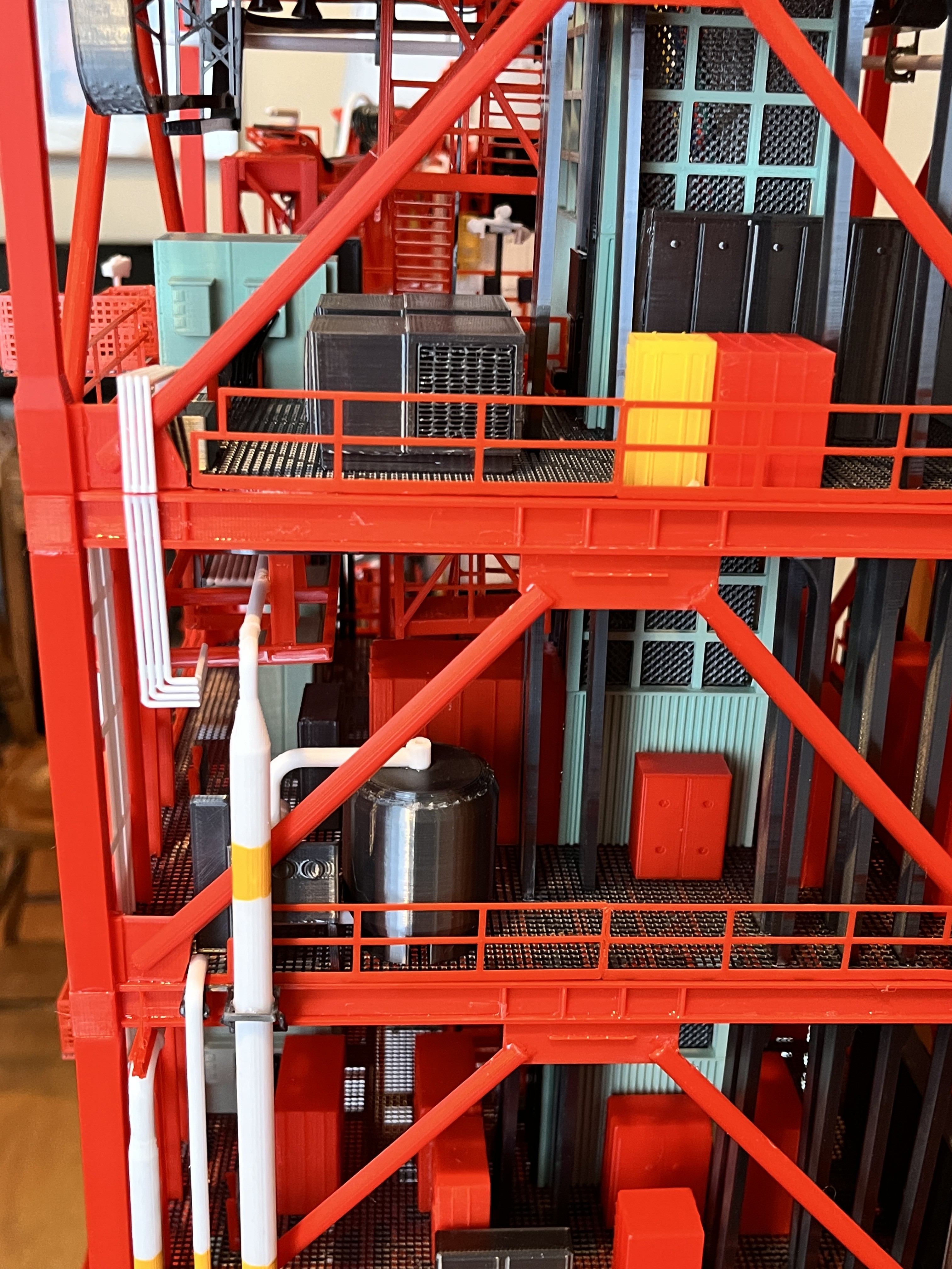
Level 280 Complete: There is a whole lotta equipment on this floor. I took off the structure to get the E2 pipe mounted on the underside and took a picture before re-installing. You can also see L260-280 lit from side 3 and side 4 because everything looks better when lit. I did not install the cables and support coming down from the next higher level. That will be added once the next level is added along with underside cable trays. One other thing of note. If you look closely at the legs going into L280 you may notice that this is not the newly designed floor beams. I had already printed this part before realizing I needed a re-design. Every floor from this point on will have the new design where the next level legs will fit down into the floor a bit. For this level, since it is glued, I will carefully glue the old style legs to the flat surface. The newer legs have a tab that fits down into the floor. There are also new 12" cross braces that are a bit longer. These fit up tight. I decided many levels ago not to create cross beams that gradually get longer as you go up but at this level I had to create new ones. You can also see that I am still adding the wires to the 138.HydropneumaticConsole parts.


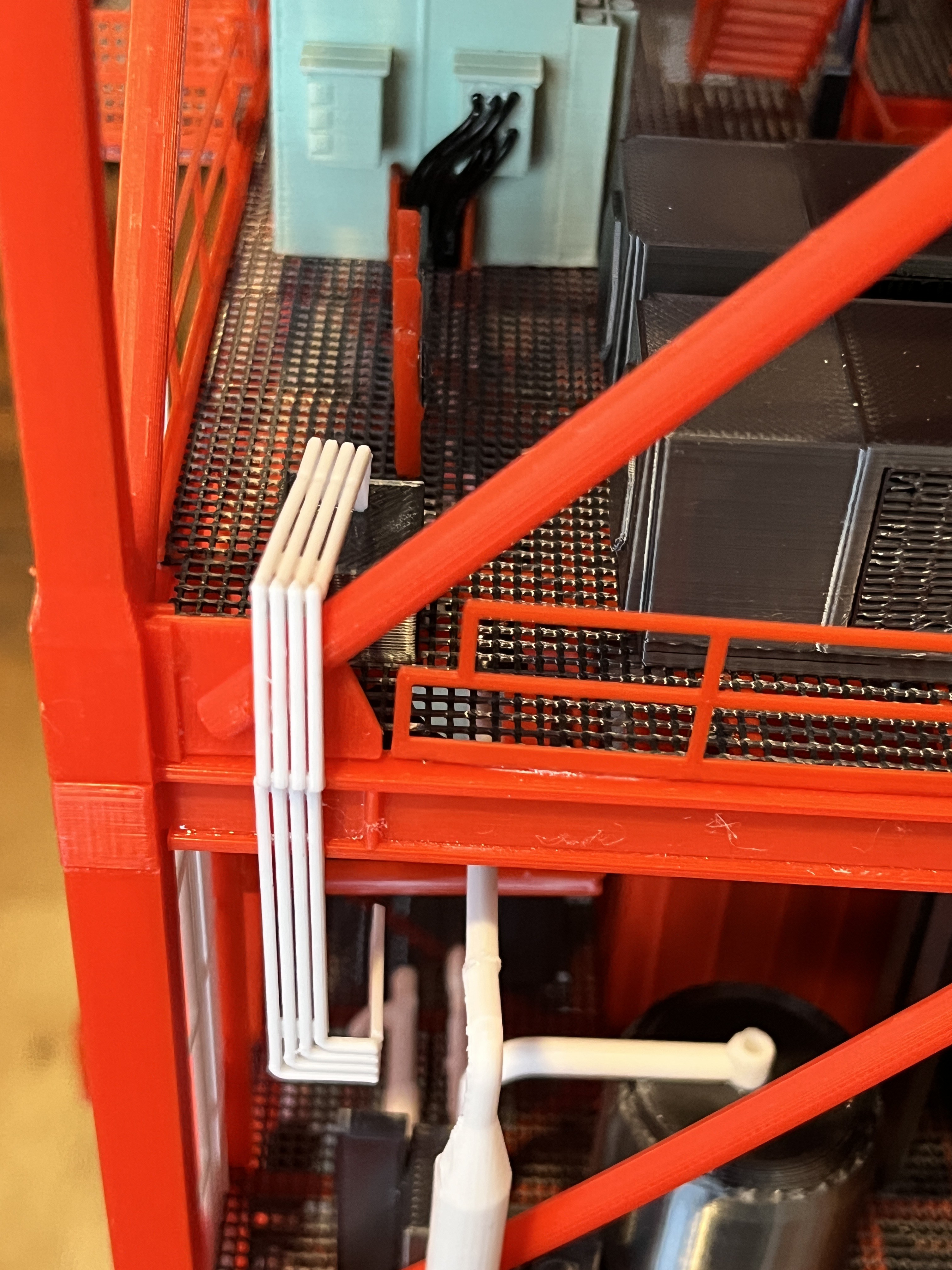
This little flow control box has pipes that go down one level and the pipes are split between two sections so I printed and then cut the pipes at the floor level. You can notice that I did not extend the pipes down to the box on the lower level because the pipes did not exactly line up with the box below and that would have been very noticeable so I simply turned them in and ended them. I have done this on some other pipes as well.
I keep thinking things will get easier. Level 280-300 is the last hurrah for the cable trays. This is the hardest level by far. I have been double checking parts before printing them and finding a few mistakes. There may be more. Once this level is complete, there are only two more cable trays extending upward. I need the horizontal cable trays printed so I can determine the placement of the ceiling lights. The lights need to be added before the cable trays go on. It looks like two of the lights may have been attached the underside of one of the cable trays. I will not add this complication. Things will look cleaner without this given the size of the wires (and they are pretty small).
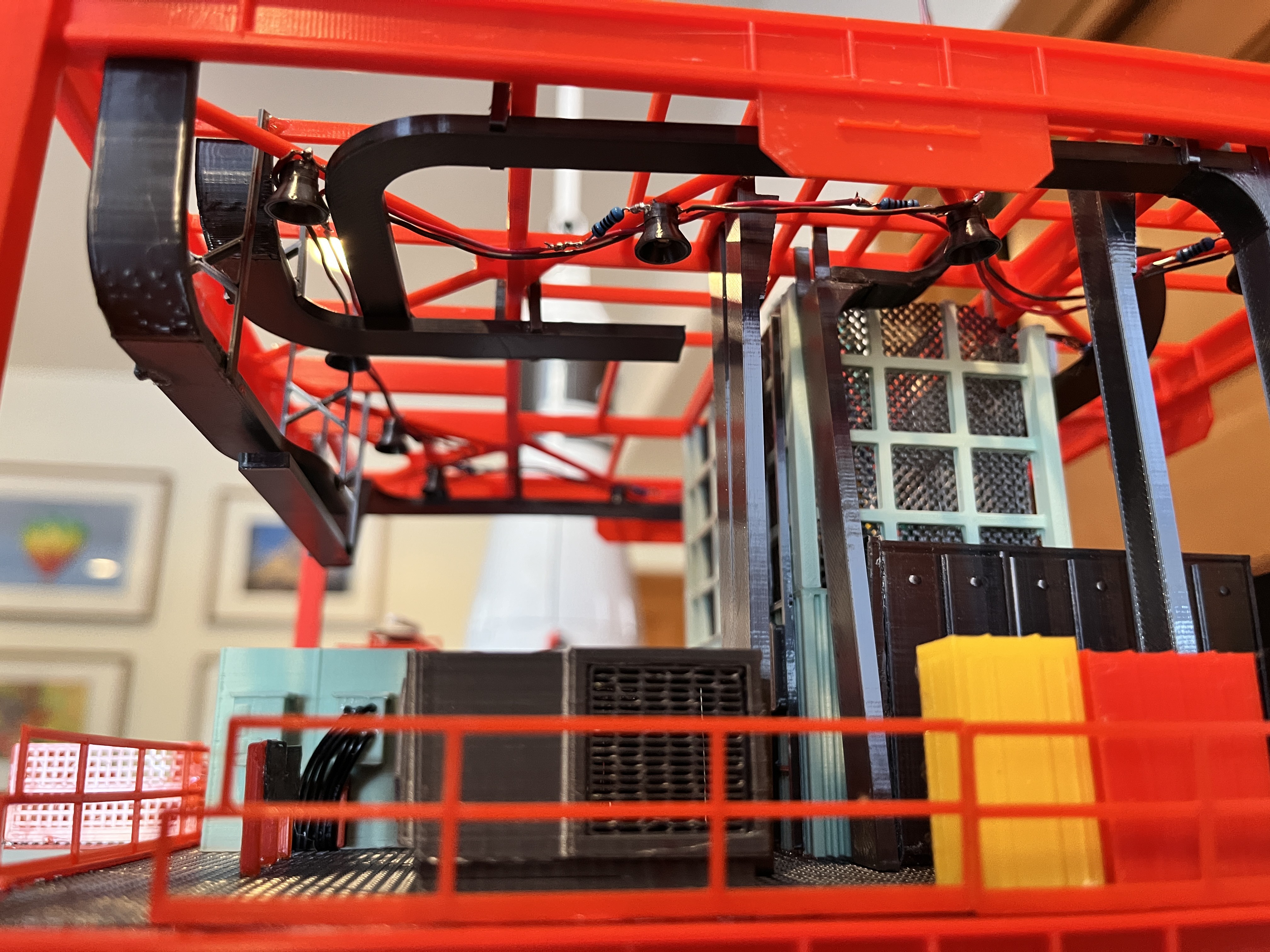
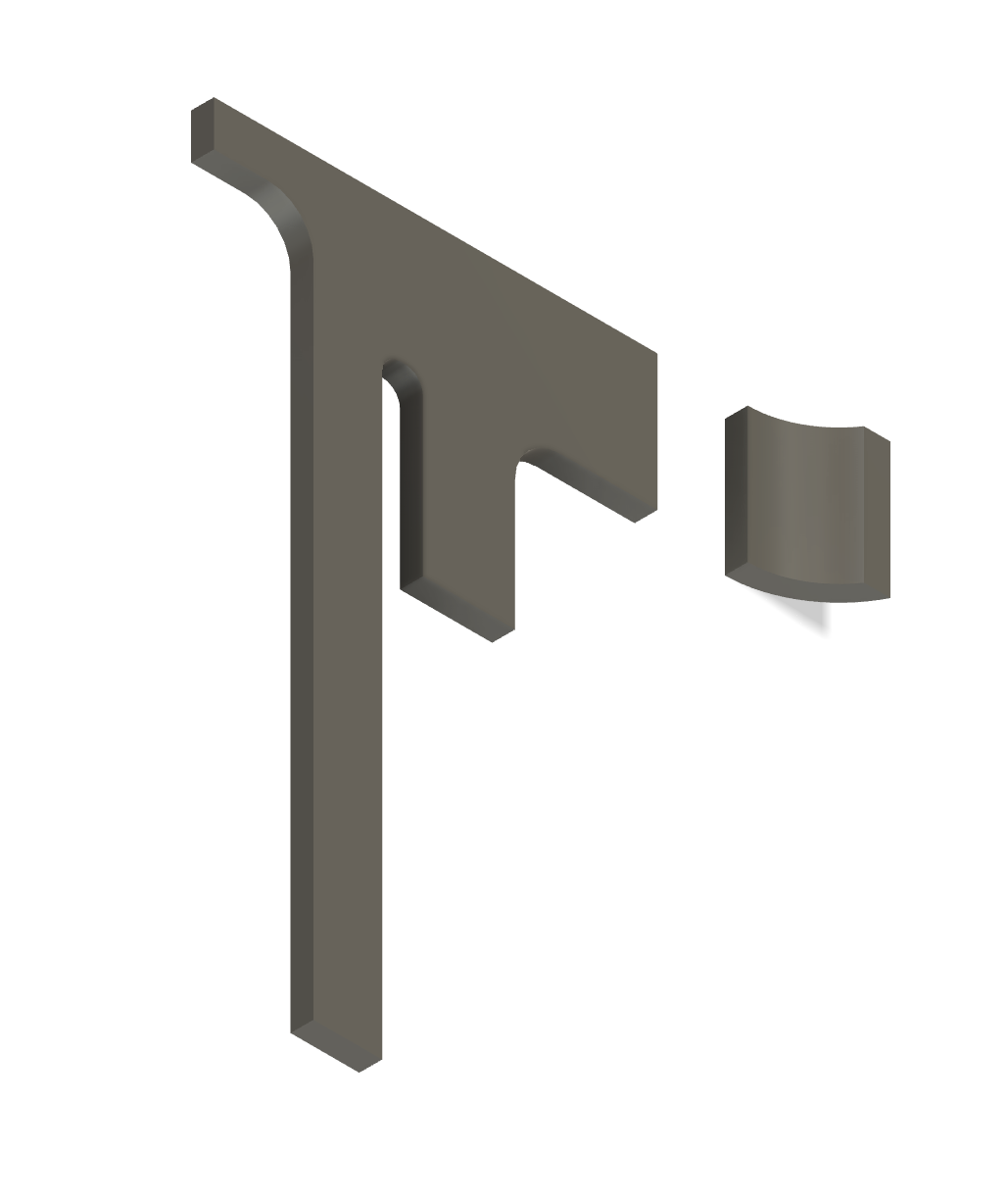
Here is a unique cable tray. After designing it over a year ago, printing it and then trying to fit it in I realized it fits between the floor beams and the cross braces. There is just enough room to slide it in, but one of the larger cross beams is in the way so I cut off the part that curves up towards the floor, slid the remaining portion in place, glued that in and then glued on the cut off part. You can see that I updated the part so the curved up piece is separated from the main part. Once the floor grating goes on, this cable tray is tucked up so close to the floor that it will be hard to tell this cable tray is in two pieces.
The Level 280-300 cable trays are in. There were a few part updates. It would have been really difficult if not for the removable sections. It is best to take the top section off and work on it on the workbench. You can see the tower is now up to about eye height and I need a step stool to continue construction.

I was unable to get the issue resolved with the base Apollo Umbilical Tower model, could not get the attention of the Printable admins... so my solution is to create a new model "Apollo Umbilical Tower - New". This is now up to date. As a part of this effort I moved the Structure parts out into three new models. The parts have not changed, just trying to divide and conquer. I'm not sure why I can no longer edit the original model so I have to abandon it in place.
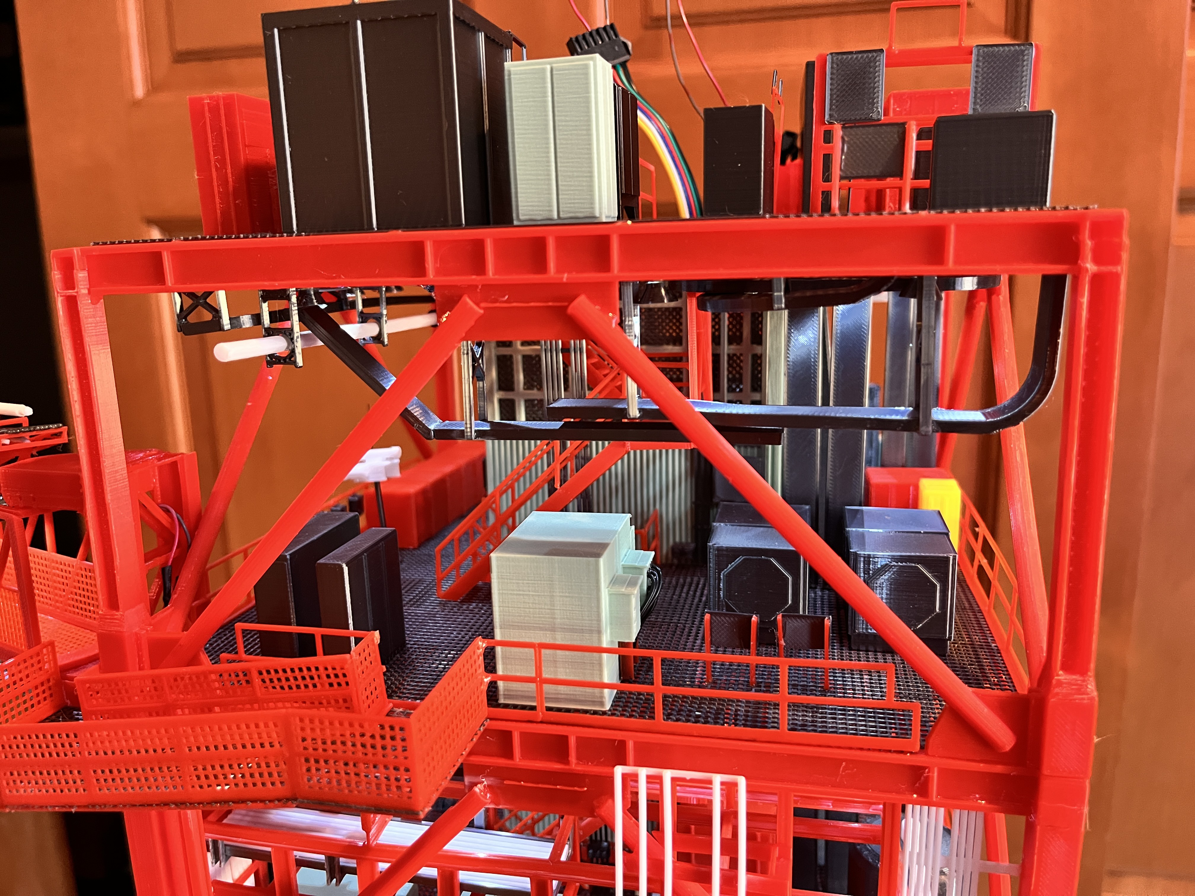
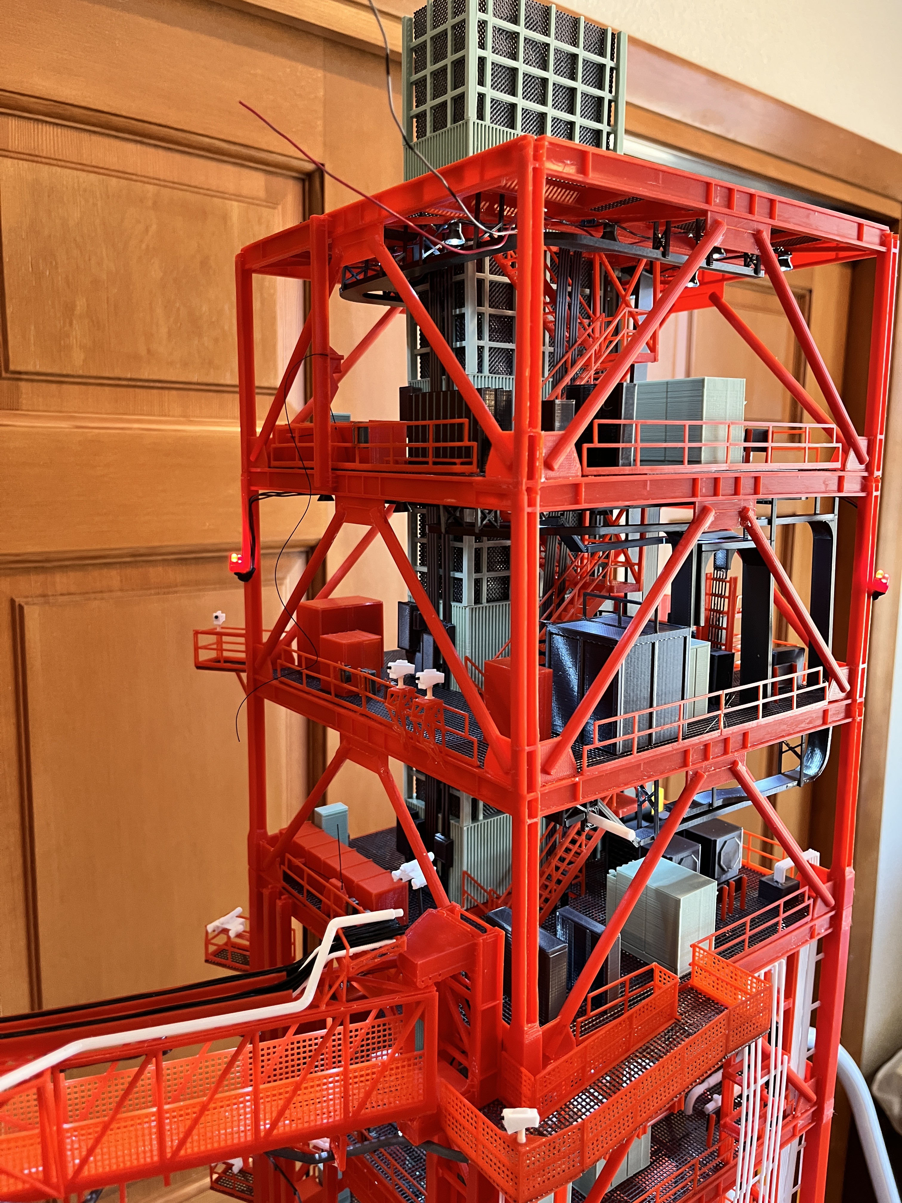
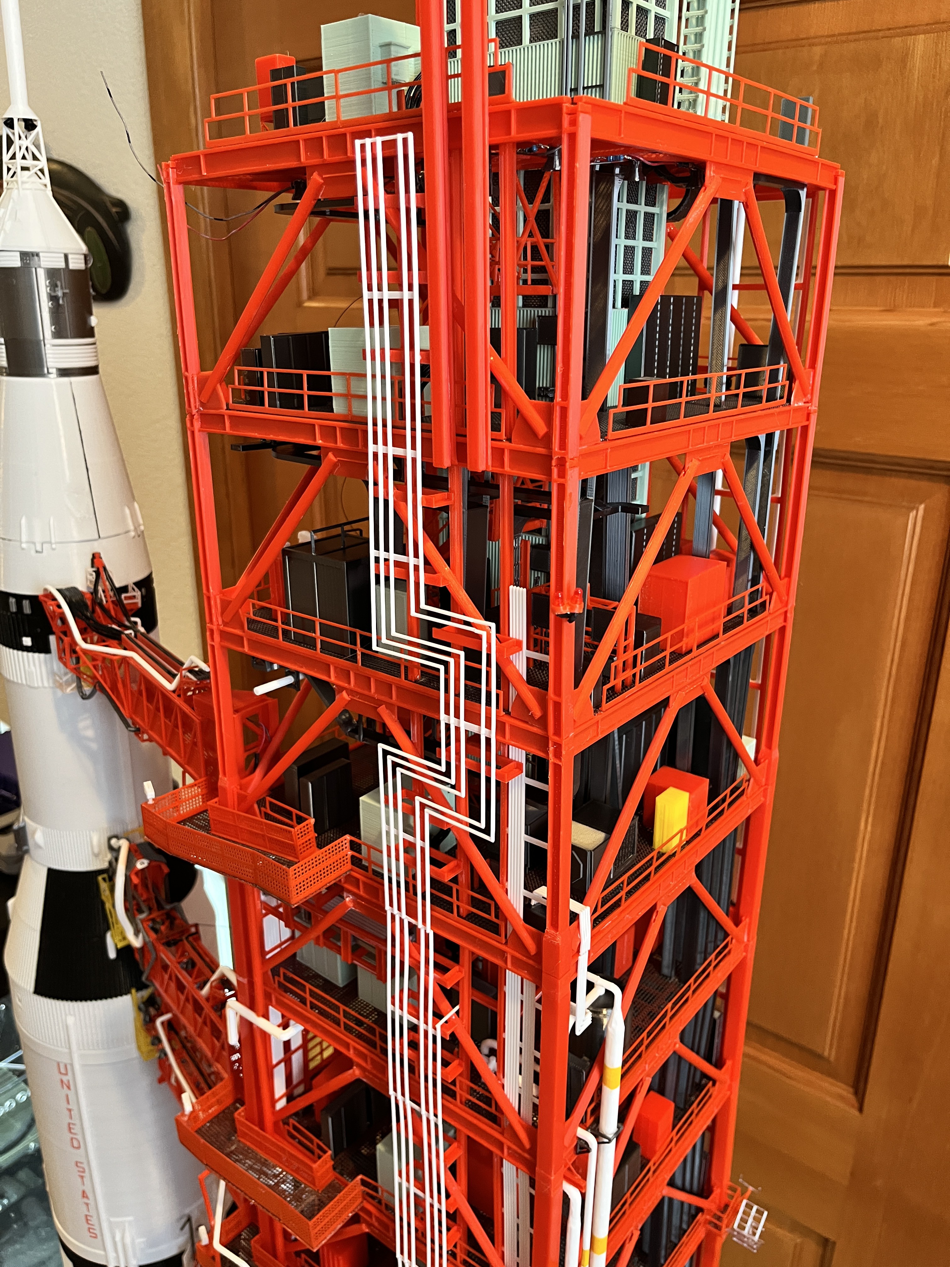
Section 6 structure and inner parts are complete. This is levels 260-320. Here are some picture with the lights on. I can just see level with the floor of level 320. I would highly recommend doing these upper sections on the workbench. With the inner portions complete, the piping on the outer structure will be added with the section in place to make sure the pipes line up. At this point only one cable tray remains.
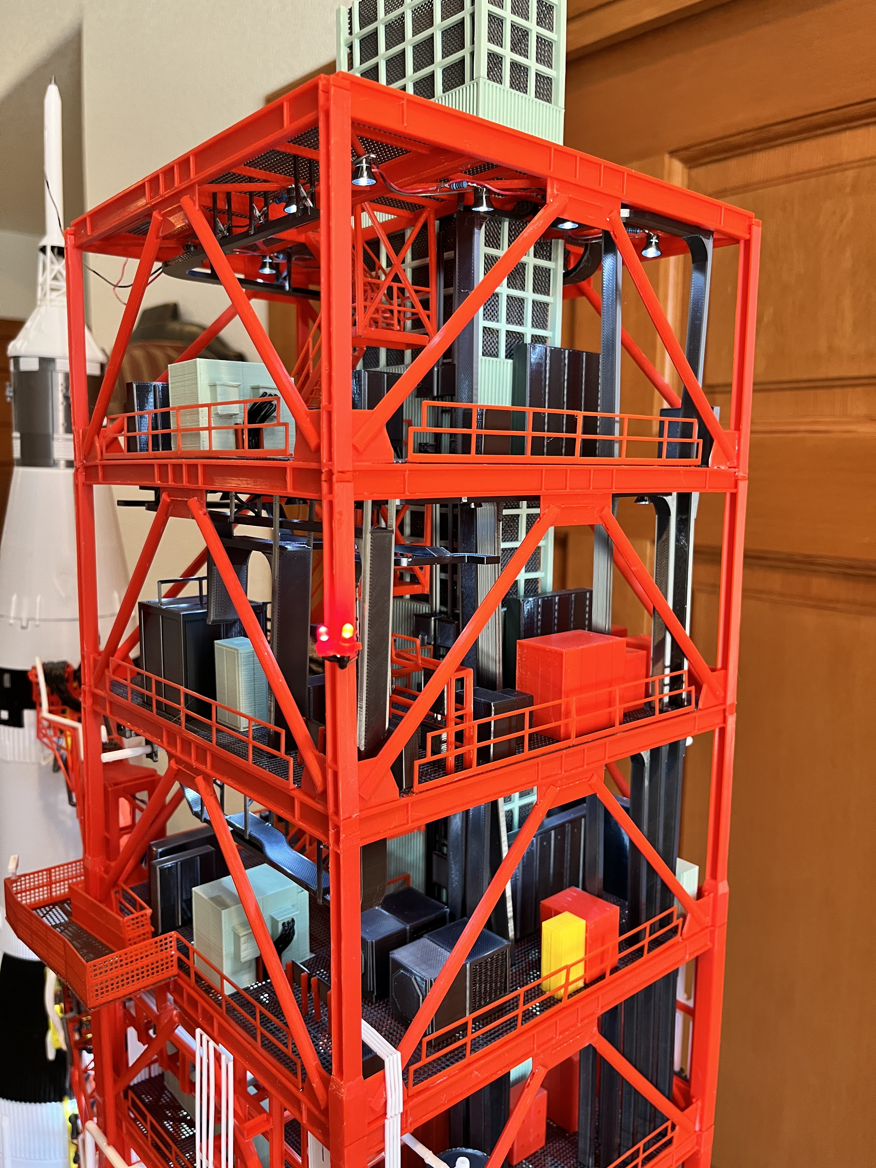
Section 6 Side 2 Complete: Two of the water pipes end part way up the next level so I extended them from here. This will help anchor the next section. Side 3 is also complete because there are no more pipes left on that side. Also the equipment on Level 320 has been added.
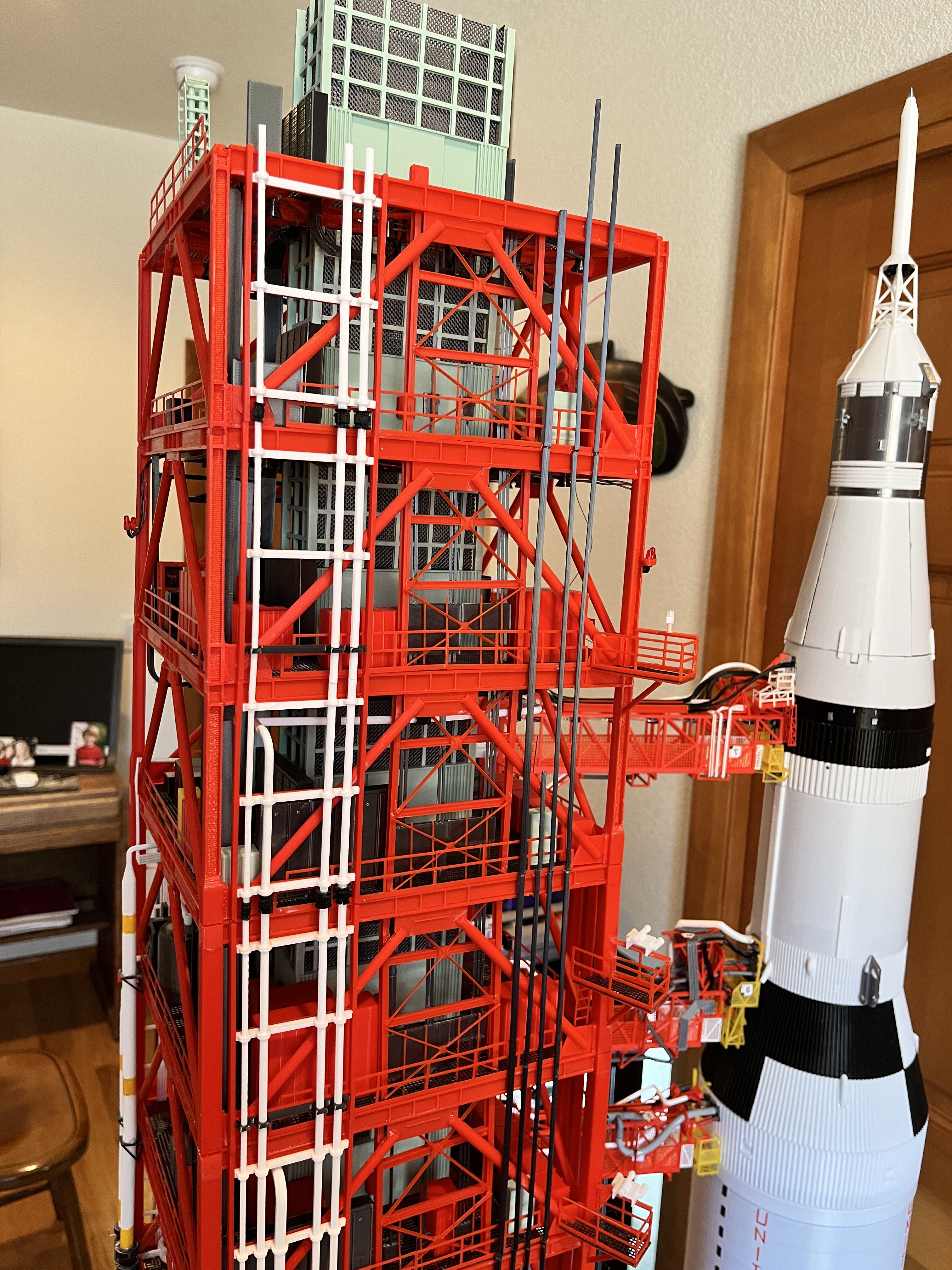
Section 6 Sides 1 & 4 Complete: In the first picture you can see that the cables ended. Since there wasn't much I could find on these I ended the 4 cable bundle at the same level the 4 cables go out of side 3. Visually that makes sense. It looks like the Turbo Squid drawings show the other bundle ending the next level up. The second picture shows the locking columns ending one level above this section. All I need to do now is add the support columns to this corner. The support column for side 1 ends one level up just like the locking columns. The support column for side 4 ends two levels up.
Section 6 is now complete, ready for swing arms #8 and #9. There should be enough additional support now to keep the last section relatively anchored.
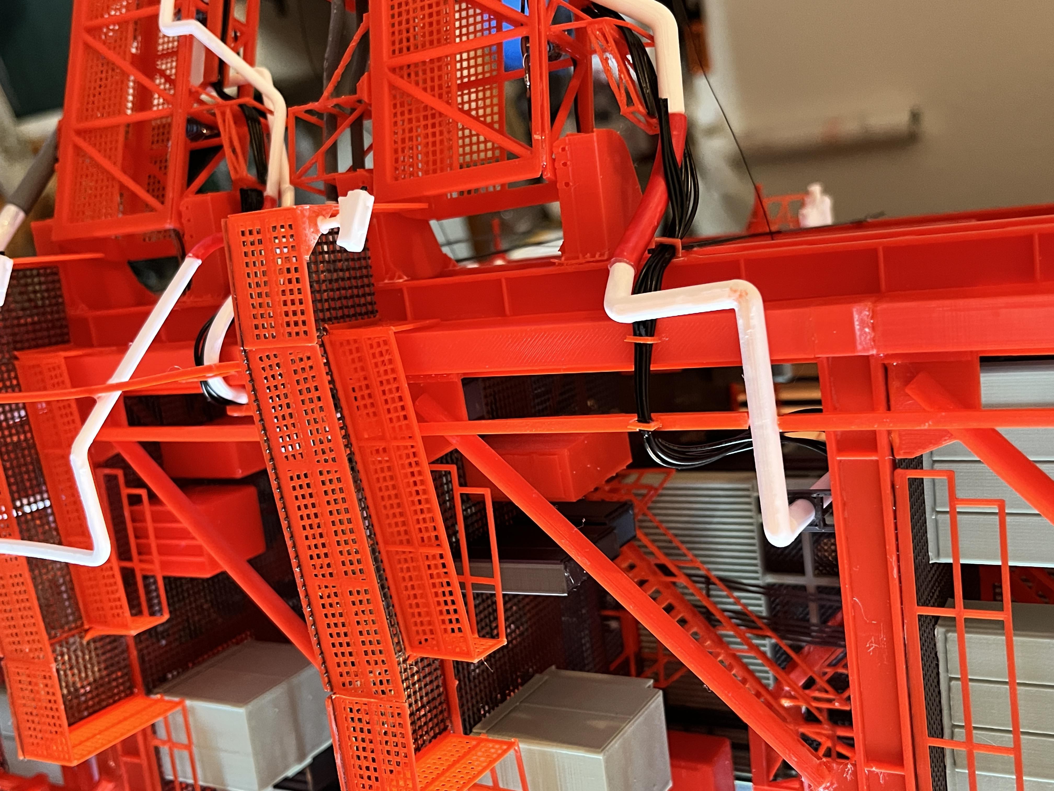
I went ahead and extended the black cabling from swing arms 4,5,6 & 7 around the side 1/4 leg and either to a cable tray or just to the ceiling. I made little brackets that hold up to 6 - 28 gauge wire.


Discussions
Become a Hackaday.io Member
Create an account to leave a comment. Already have an account? Log In.