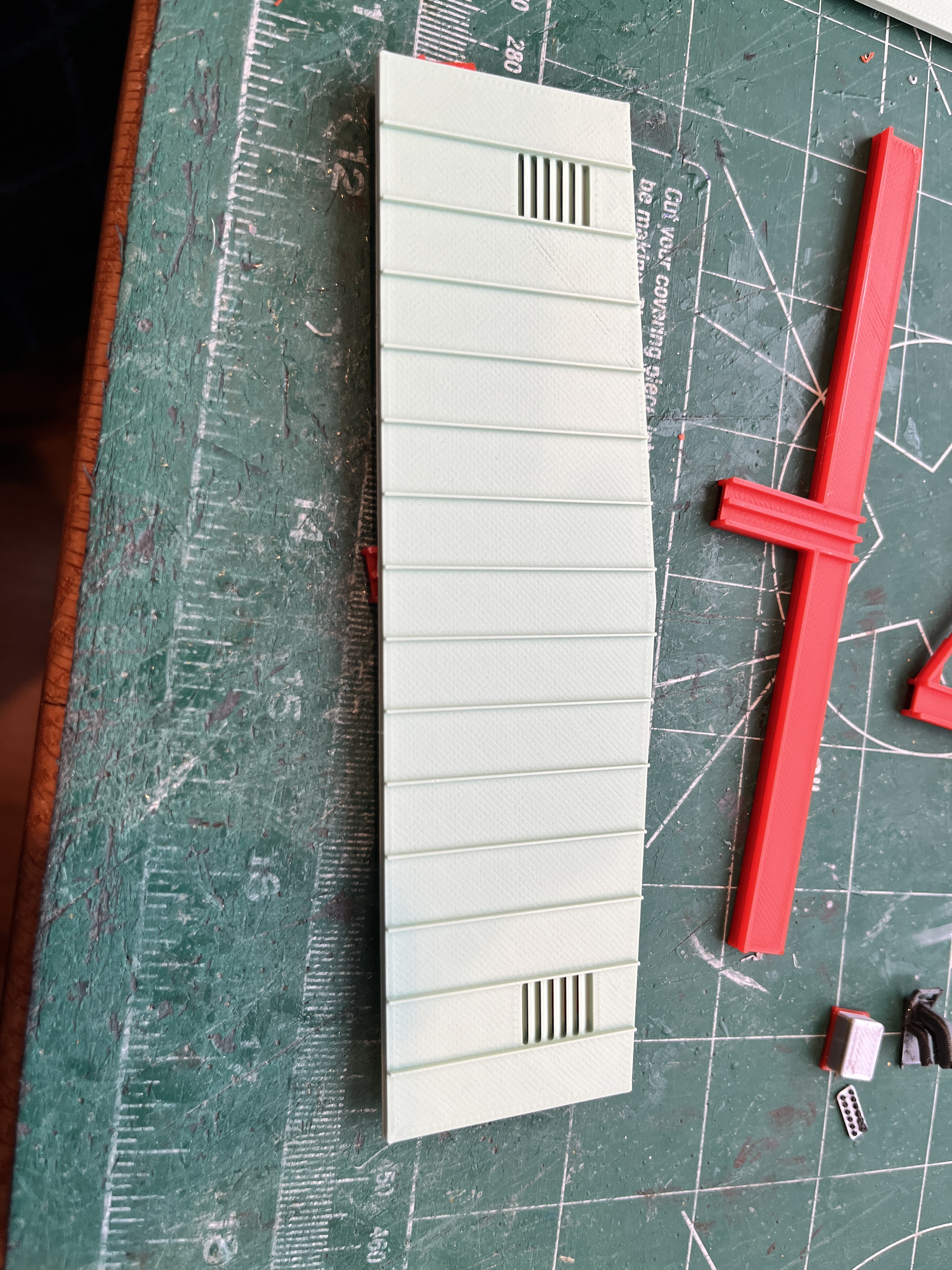
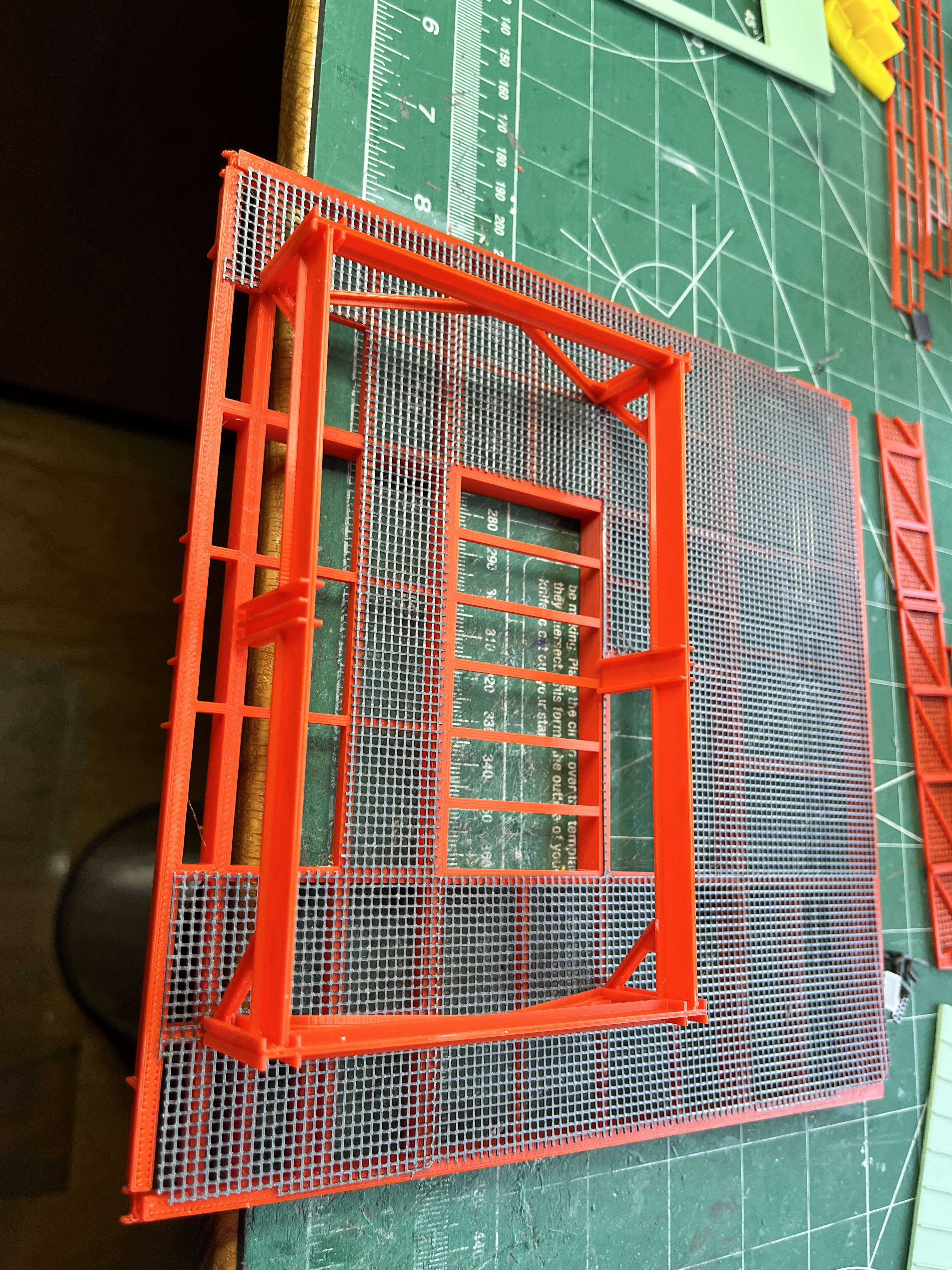
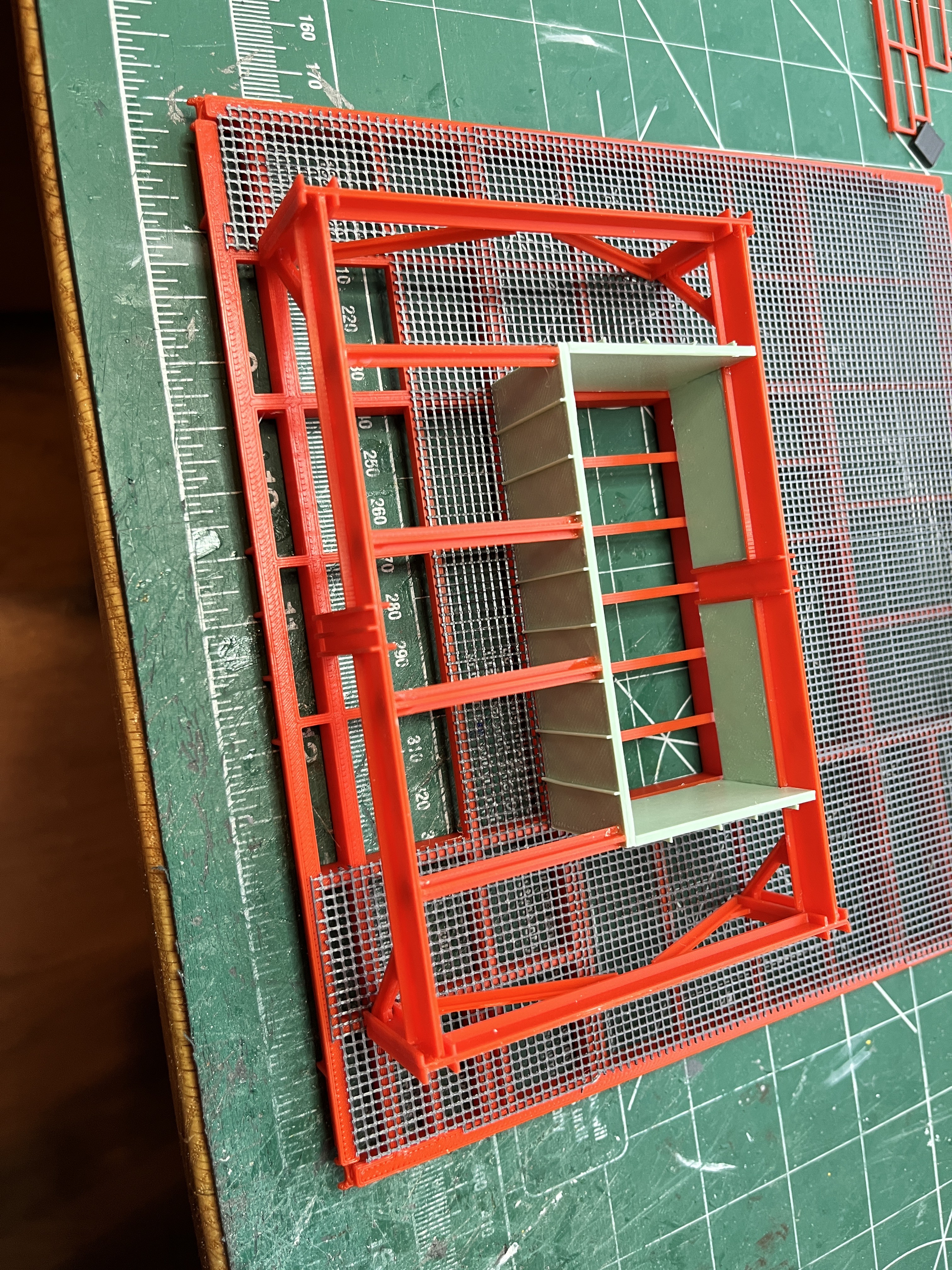
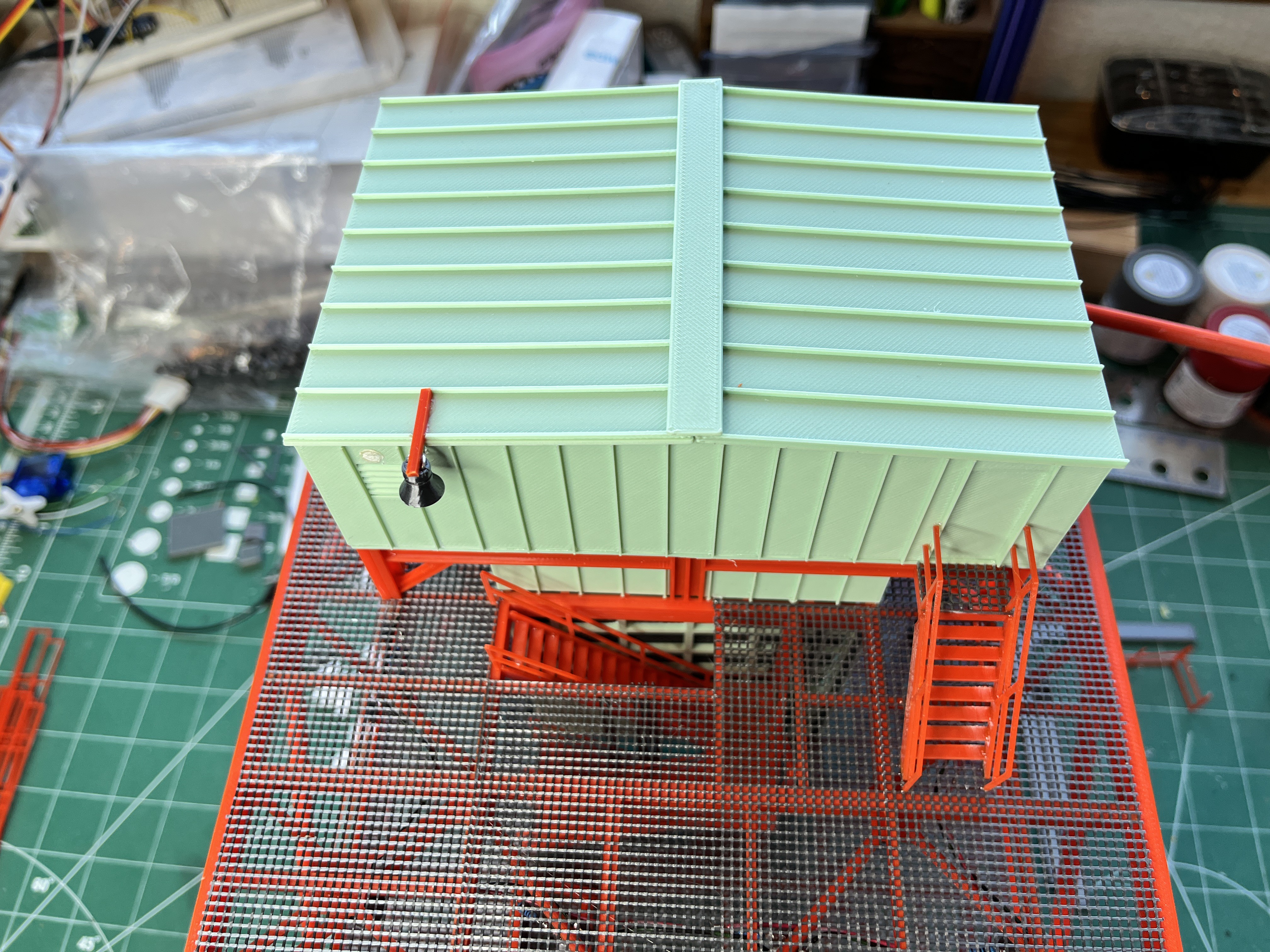
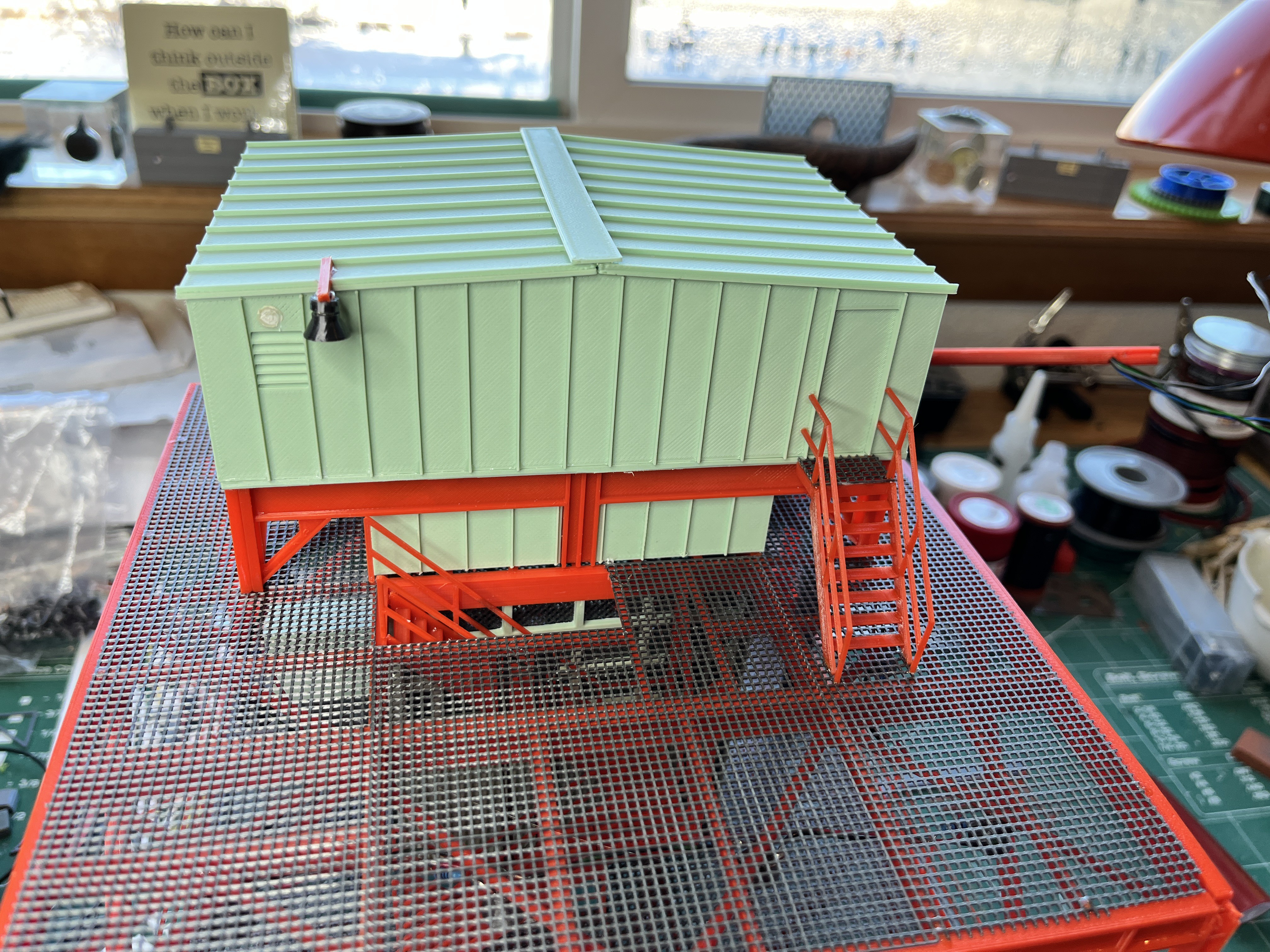
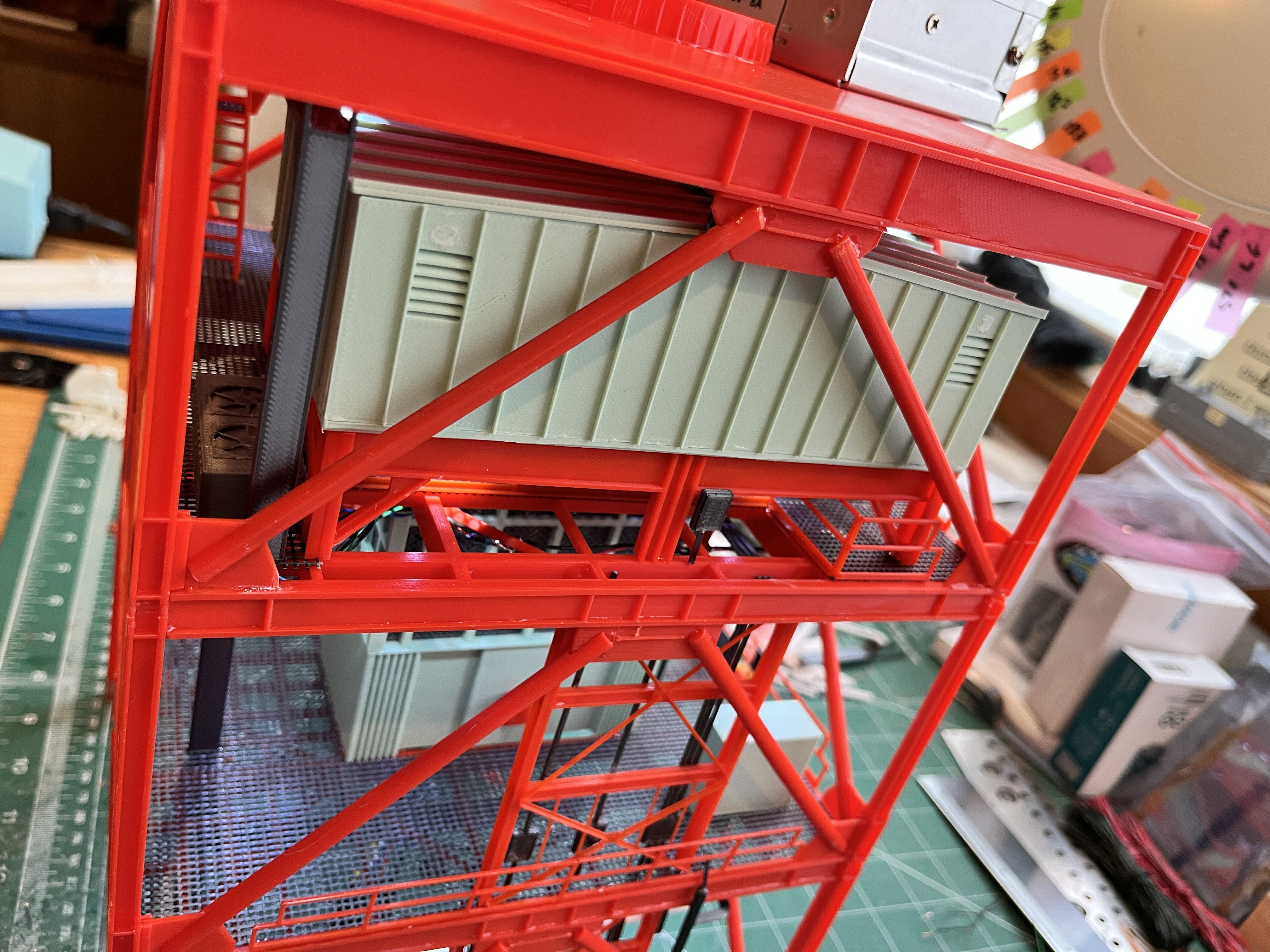
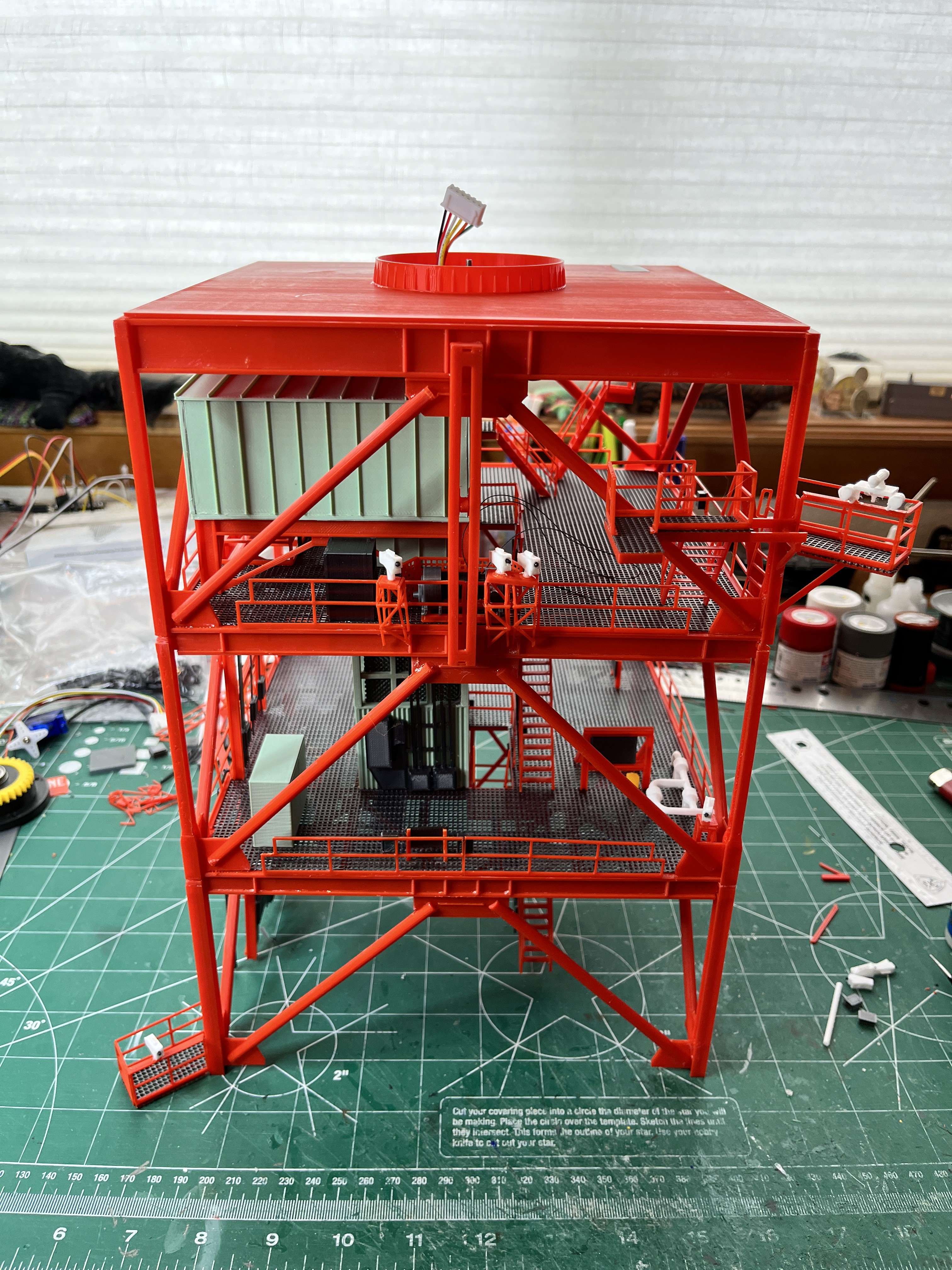
Motor Housing: The motor housing is complete except for the stairs. In the first picture you can see the floor beams with the grating cut to shape. I didn't make a specific grating. Just print up the standard grating and then cut out the hole shown. The grating and lower support structure are dry stacked. When I get to this level there is a stair railing that goes under the motor house. You can see the detail on the I-beams, even on the inside because why not. The lower section is glued together as is the floor and upper walls. I like the way the louvers printed. The roof is just laying on top. I still need to figure out how I'm going to get six brightly colored wires up to the next level. I may hollow out one of the 12" cross braces. A word of warning: The stiffeners on all the outside walls are really fragile. Be careful and you may only break off one or two like I did. I simply glued them back on. Fortunately they were on the lower walls.

Level 320-340 core is complete. This section really locks in well at the side 1/4 corner with two support columns and their tabs that fit into the floor I-beams. There is still a little bit more piping above and below this floor. There is a funky joint in the lower ECS pipe. The additional piping above/below the floor is part of the water pipe going over to the swing arms.

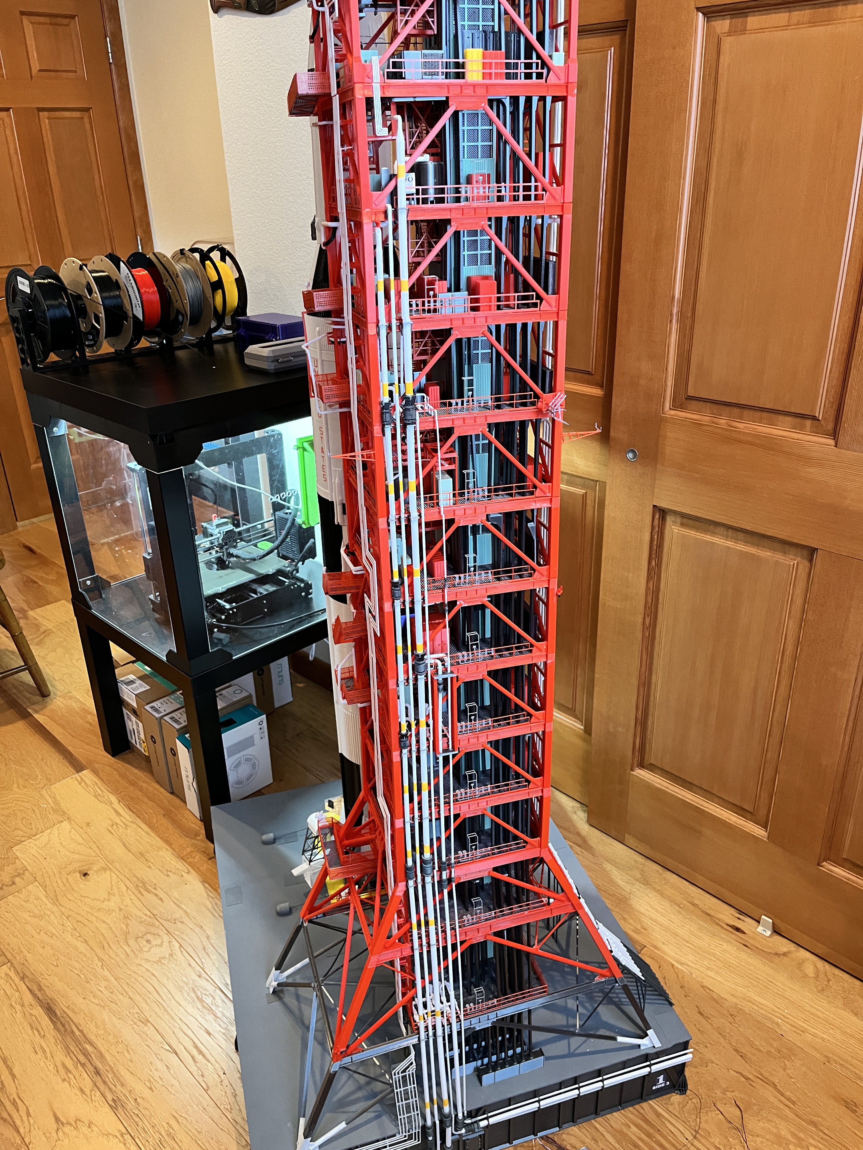
And just when you though the tower legs were getting too spindly... I give you the last taper to the final I-beam size.


Level 340 equipment in place. There is almost no equipment on this level. The build is definitely gaining speed because of this. I decided to include the little yellow box shown on Turbo Squid because why not.

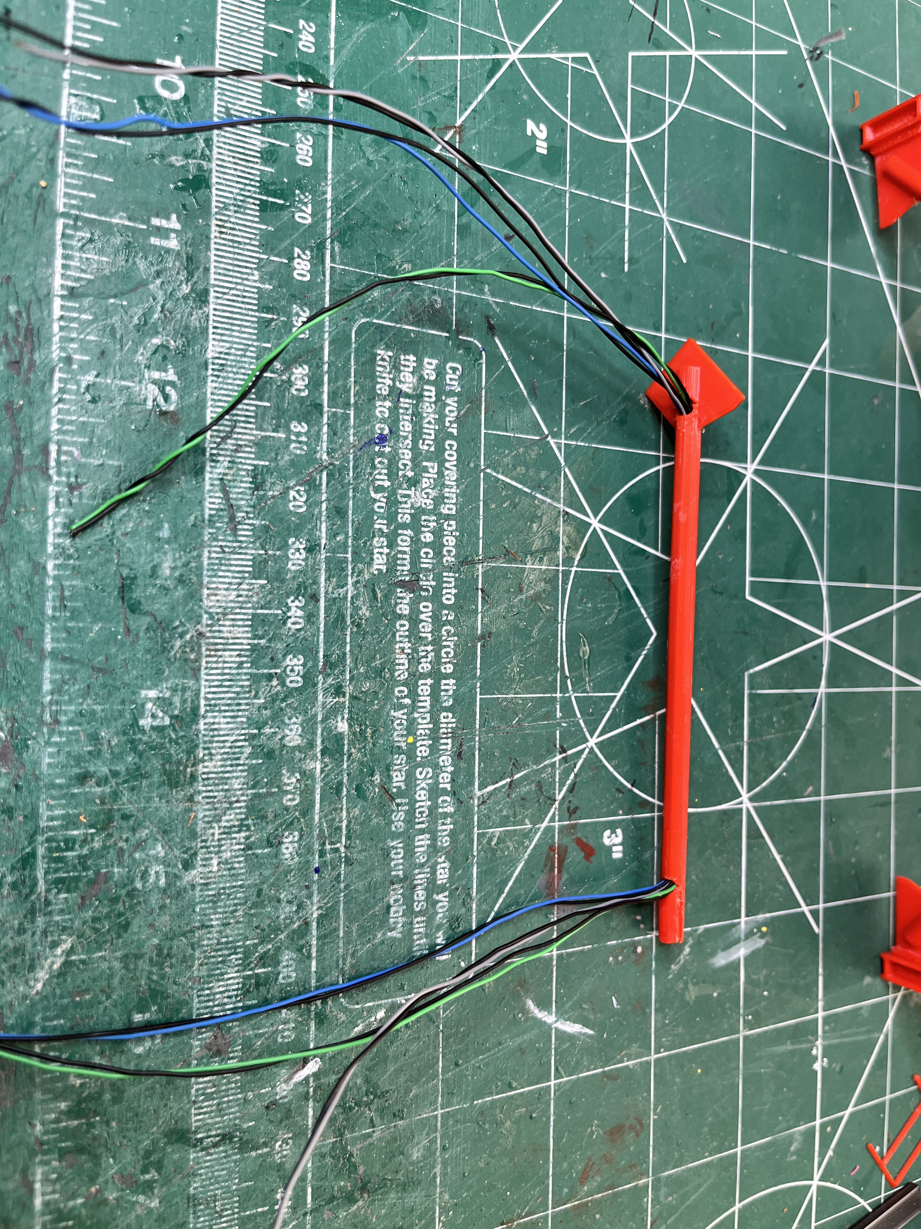
Thinking ahead... At the next level I have to route six wires up into the crane. The wires have been routed up through the elevator shaft but that avenue ends at the motor housing. I don't want strange wires coming out of the top of the motor housing. As you just saw the legs are spindly I-beams that won't hide anything. The only real alternative I saw was to hollow out one of the 12" diagonal braces. Success! This will work. at the lower corner the wires will go down through the floor grating and along the floor I-beams to the elevator shaft. At the other end the large gusset will hid the exit of the wires which will be glued to the inside of one of the central I-beams on the L380 floor to the center where they will run up into the crane compartment through the king pin.
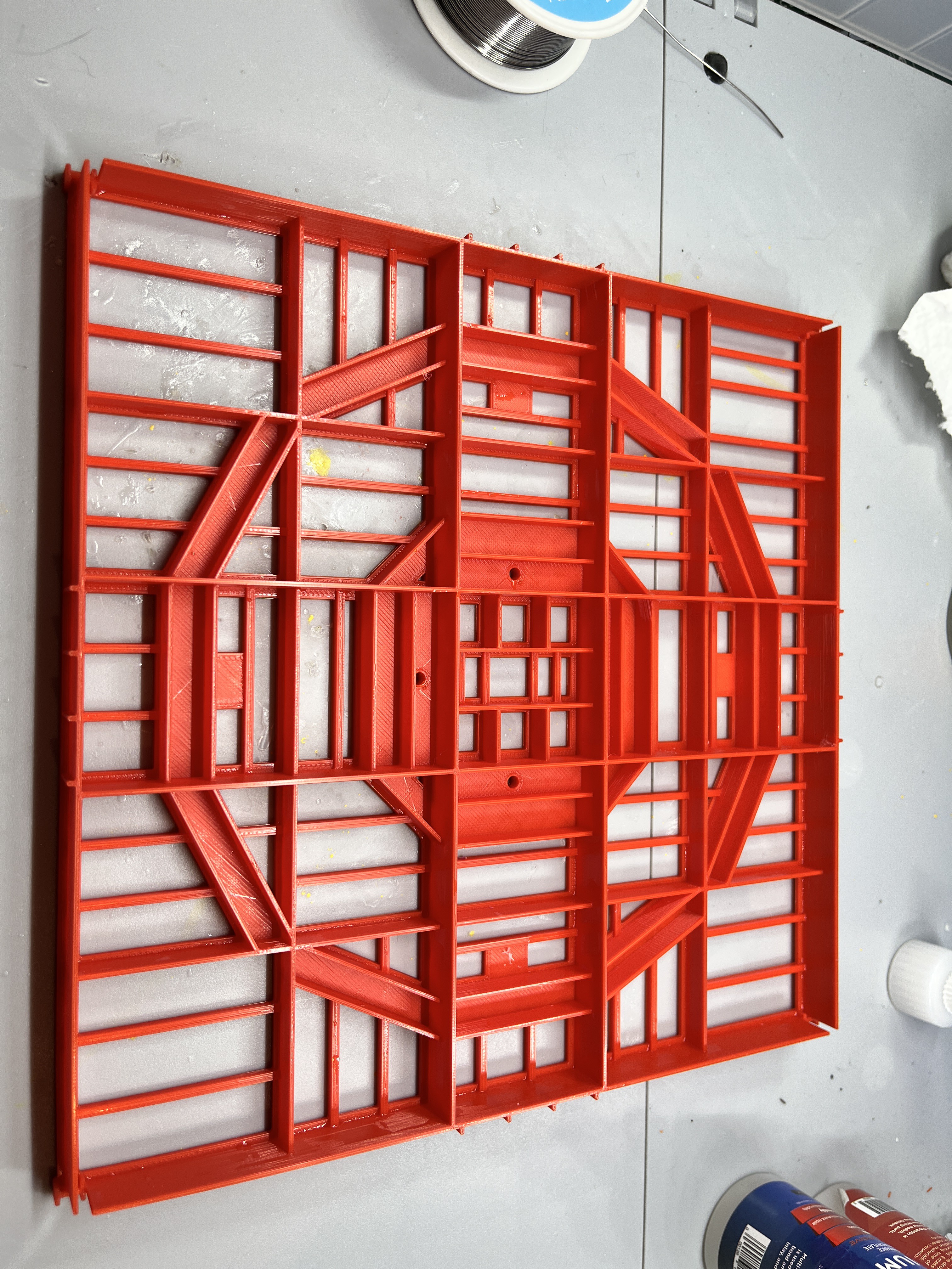
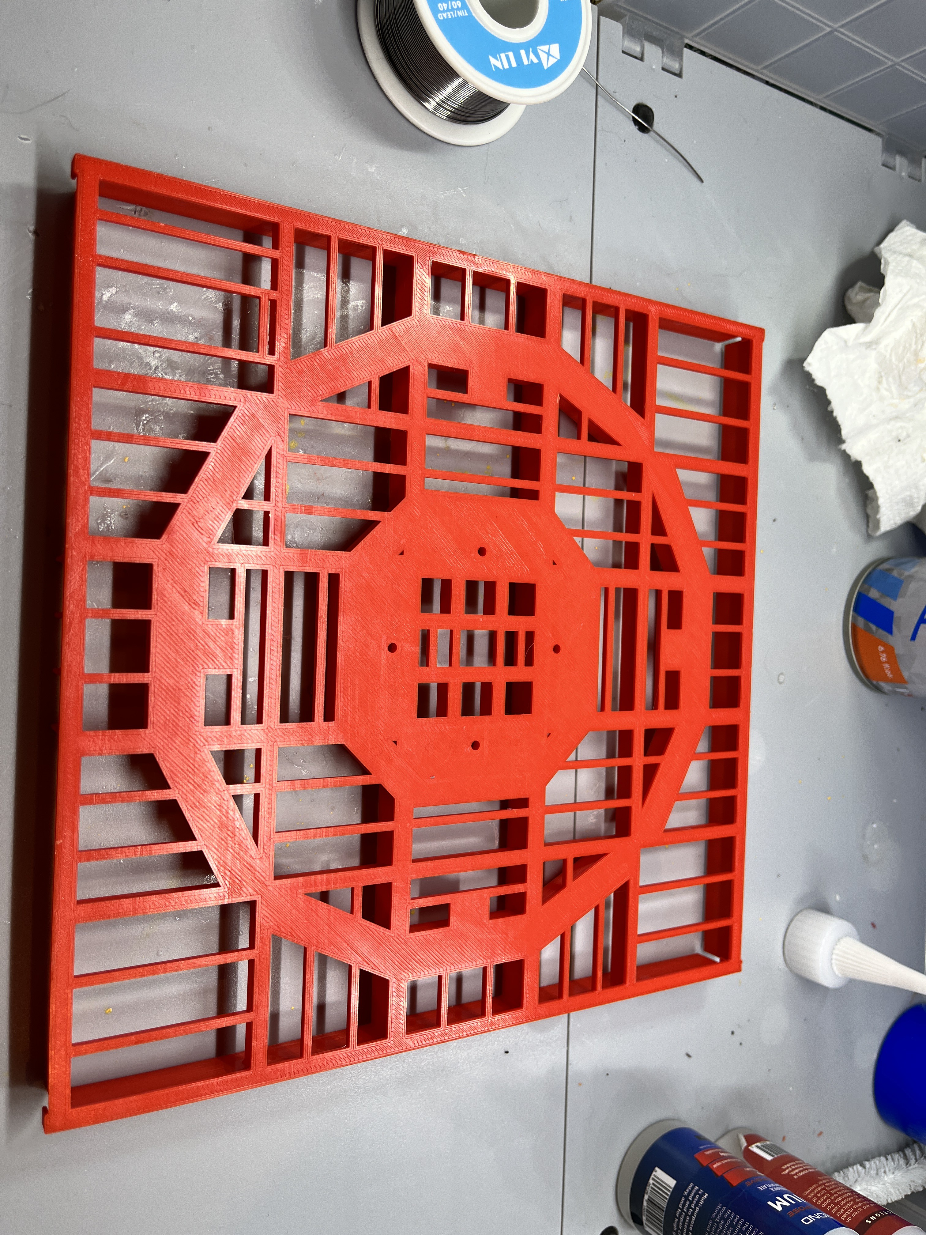
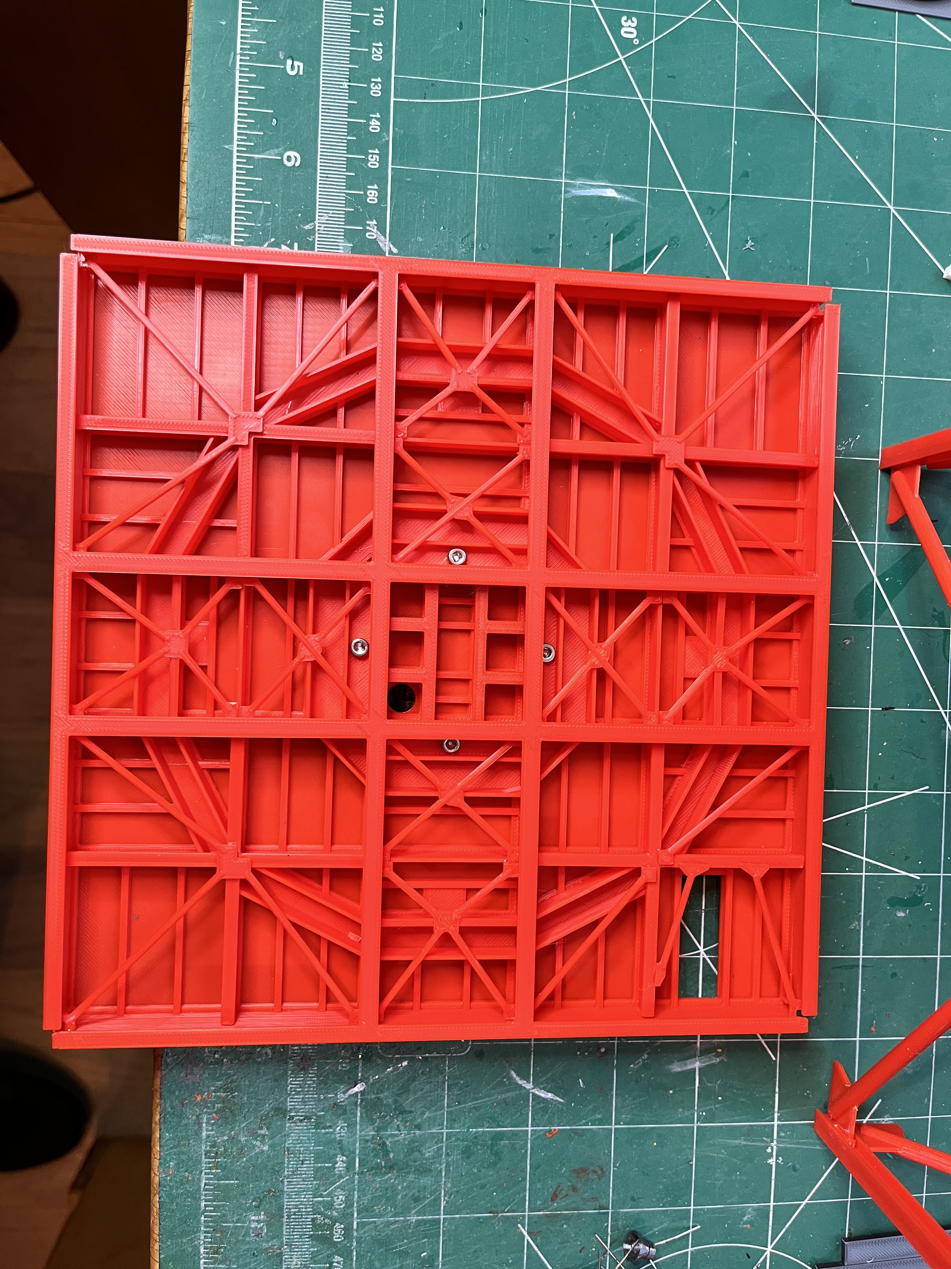
Just finished printing the L380 I-beam structure. Of the thousands of parts I had to design, this one took by far the longest time to draw up. This is the part I am most proud of. It still needs the underside flanges and braces glued on. And of course the top surface you see will be covered by a solid floor.
Ironing on the old crappy printer was really bad, so bad that I went with plastic sheeting for the launcher top. Ironing on the Prusa is really impressive.

A big thanks to John for designing and printing me a set of showers/eye wash station/water fountain parts. They are so small you need a resin printer which I don't have. To really appreciate the parts you need to look at them through a lighted magnifying glass. They definitely add great detail to the model. I added the first one to L240 since there is not much equipment here where the shower goes.


Now that I am satisfied with the direction the crane is going and understand the wiring and the way the crane will connect I am back to building the core of Section #7. I first glued up the next two levels on the model to make sure everything was straight. Now I can remove the top section and work on it on the bench. Yet another good reason to assemble this model in removable sections.


The amount of detail in your LUT is mind boggling. From the corrections of items to the collaborations between different parts and people plus all the contributions from the LUT patrons/followers that are used is staggering.
I’ve ghosted this topic since it the “LUT” was on the original website of “Save the LUT” and I can honestly say that this build is one of the best I have seen to date.
The ability to render such a beautiful model in FDM even puts the old LVM studios brass PE kit to shame.
I so very much hope to retire soon so I can begin working on this project to make one for myself.
Mr Glasford, I 🫡 you Sir.
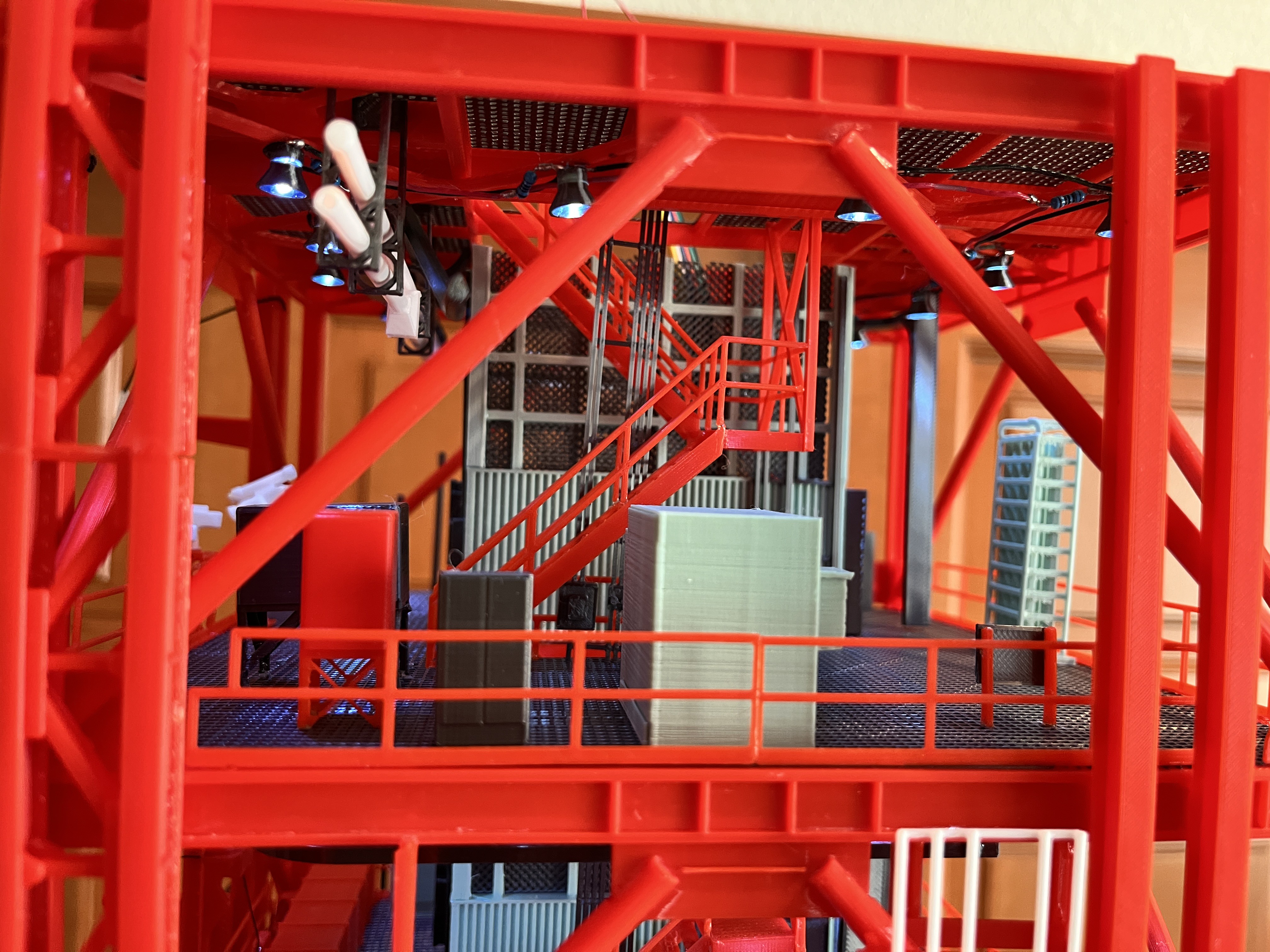
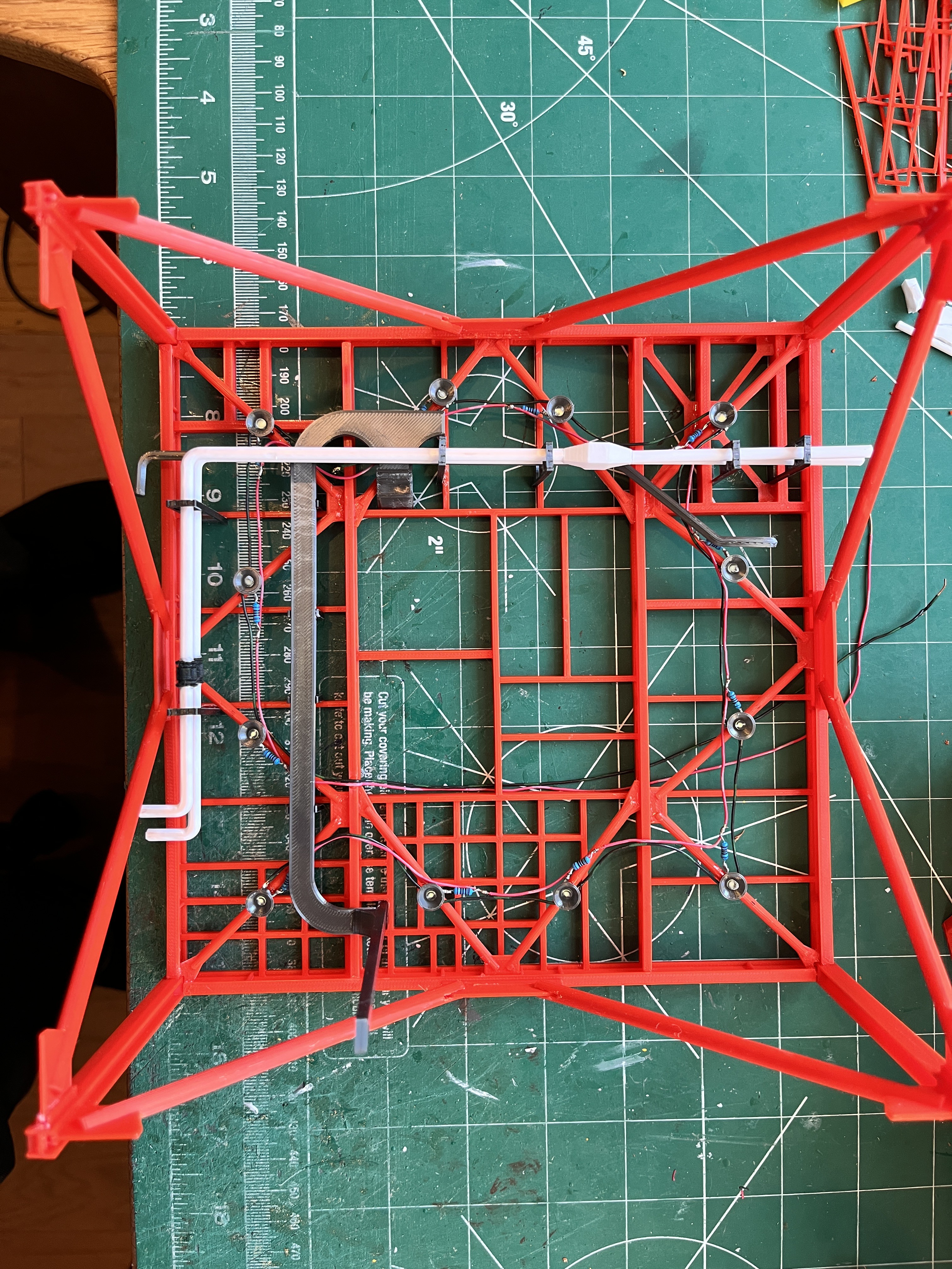
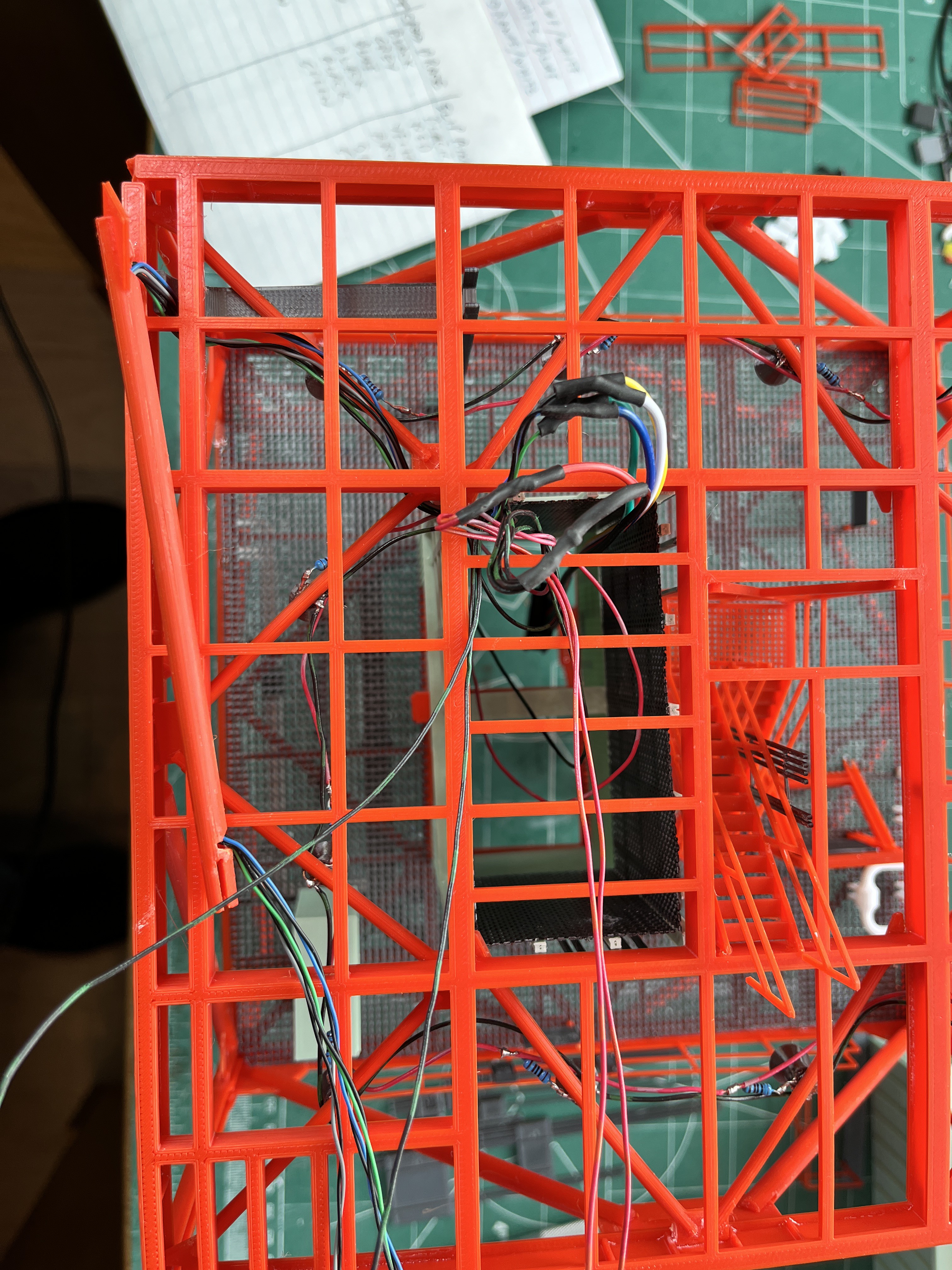
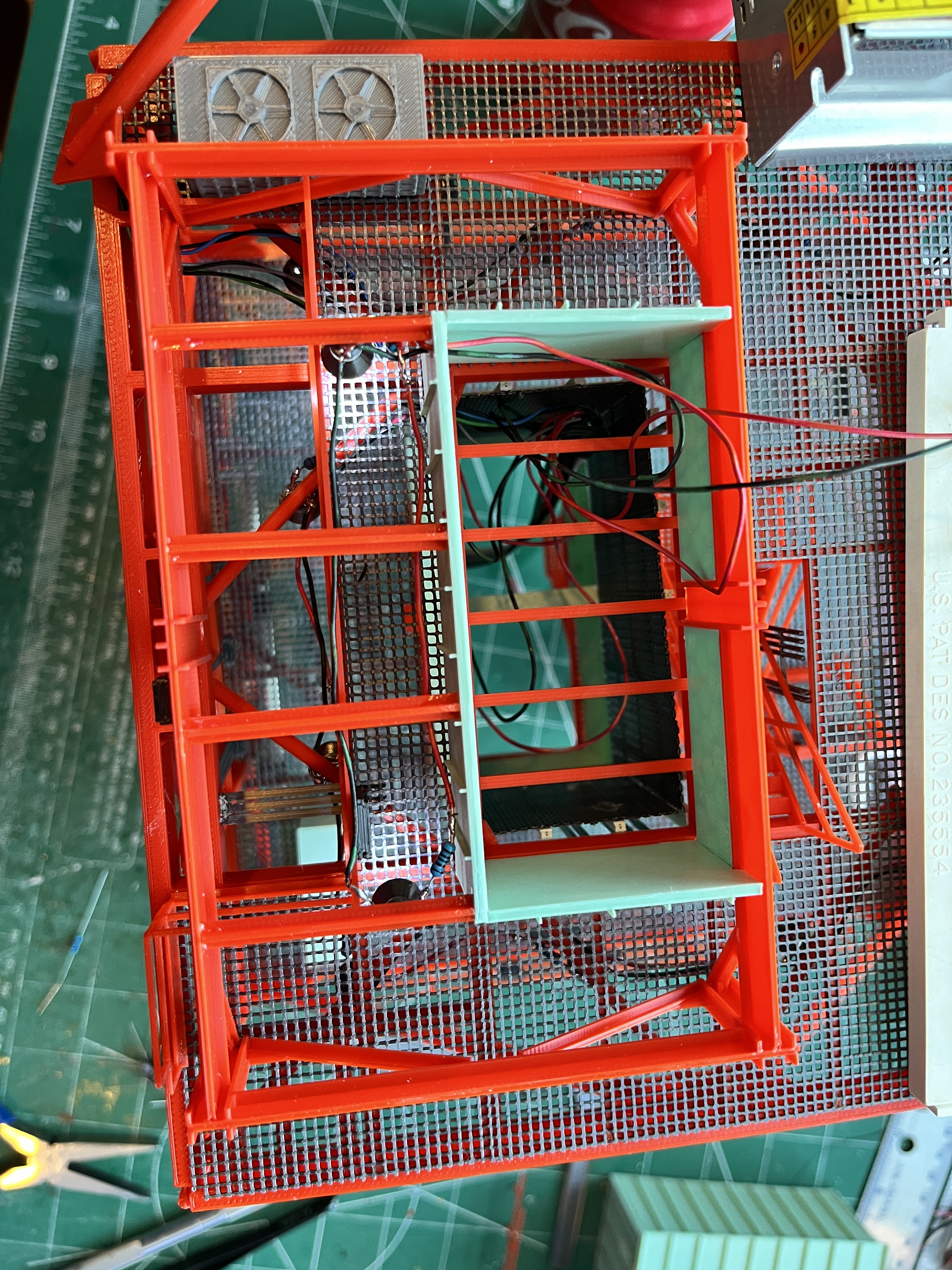
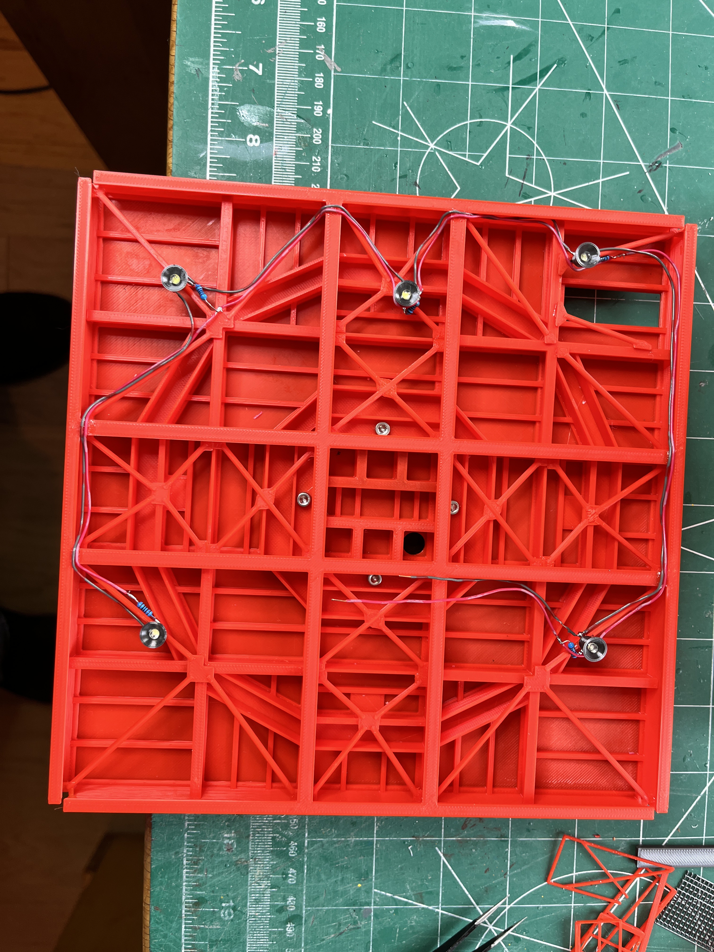
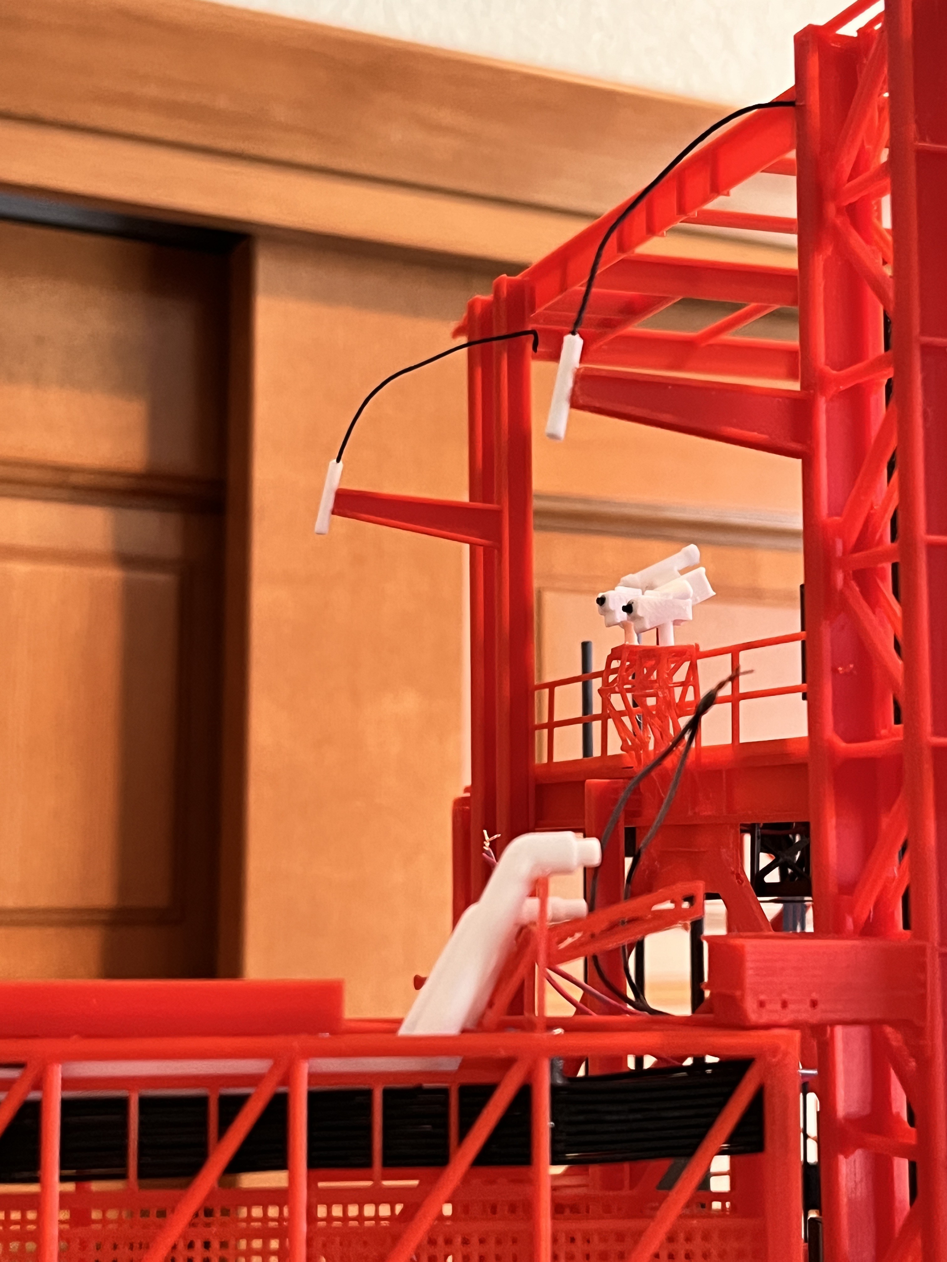
You can see a picture of the wiring for Section 7. There are only 8 lights at this level but 3 of them are sneaky. One is on a pole on the front side of the machine room and two are under the motor house lighting the narrow walkway on the back side. This is why I have added two pairs of wires to what's left of the wiring harness inside the elevator shaft. You can also see the 8 main wires going out to the edge of side 2 and then inside the 12" cross brace to go up to the next level without seeing them.
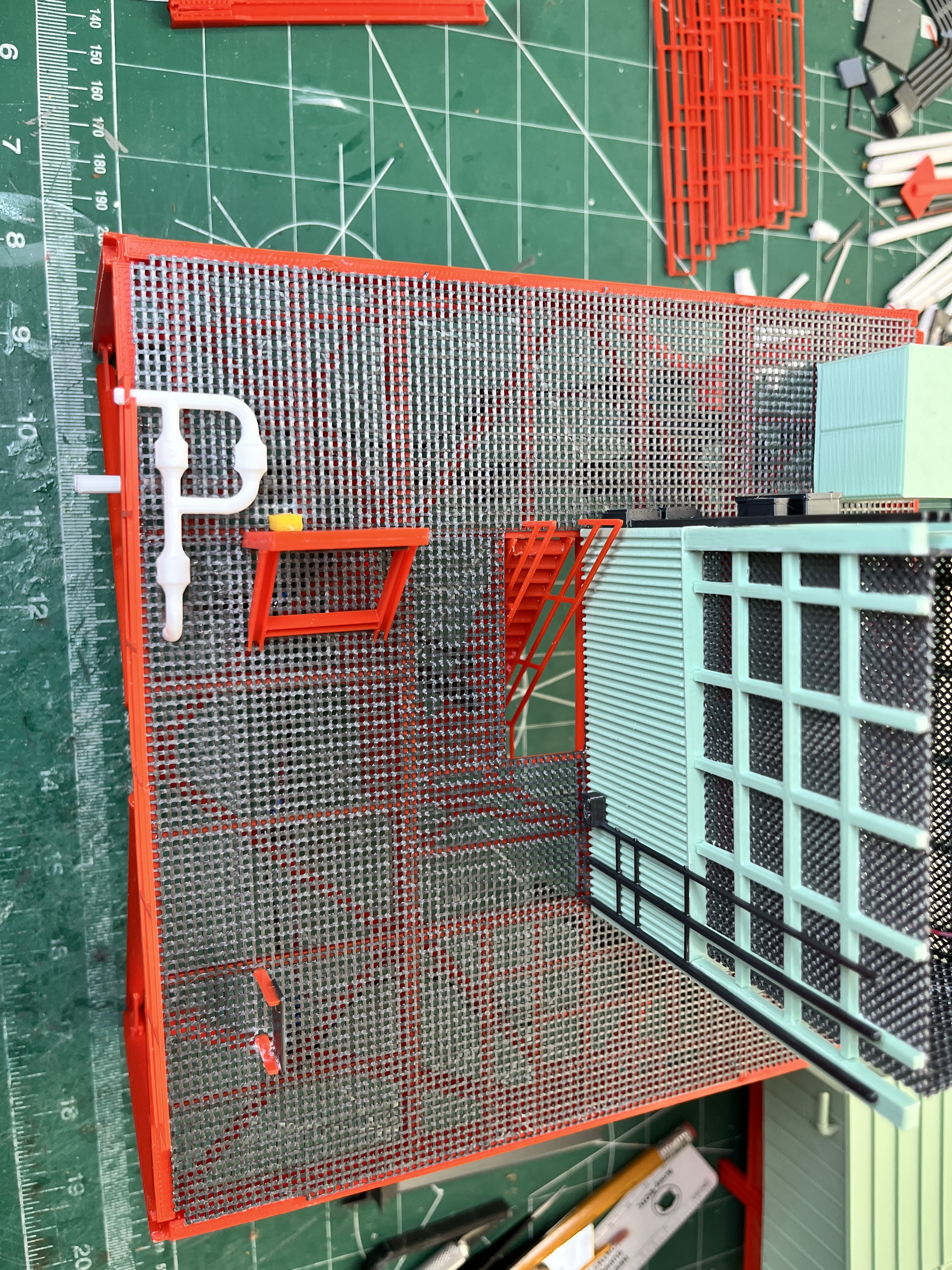
Once the wiring is in place I glued down the floor grating and then added the inner railing on side 2. Notice that all those cables that went up the middle of side 2 finally end in two boxes. One is glued to the inner railing and there are three cables glued to the underside of the floor and the other one is glued to the machine room support frame. Speaking of motor house support frame, that is then glued down. The two under machine room lights are now ready to be installed.

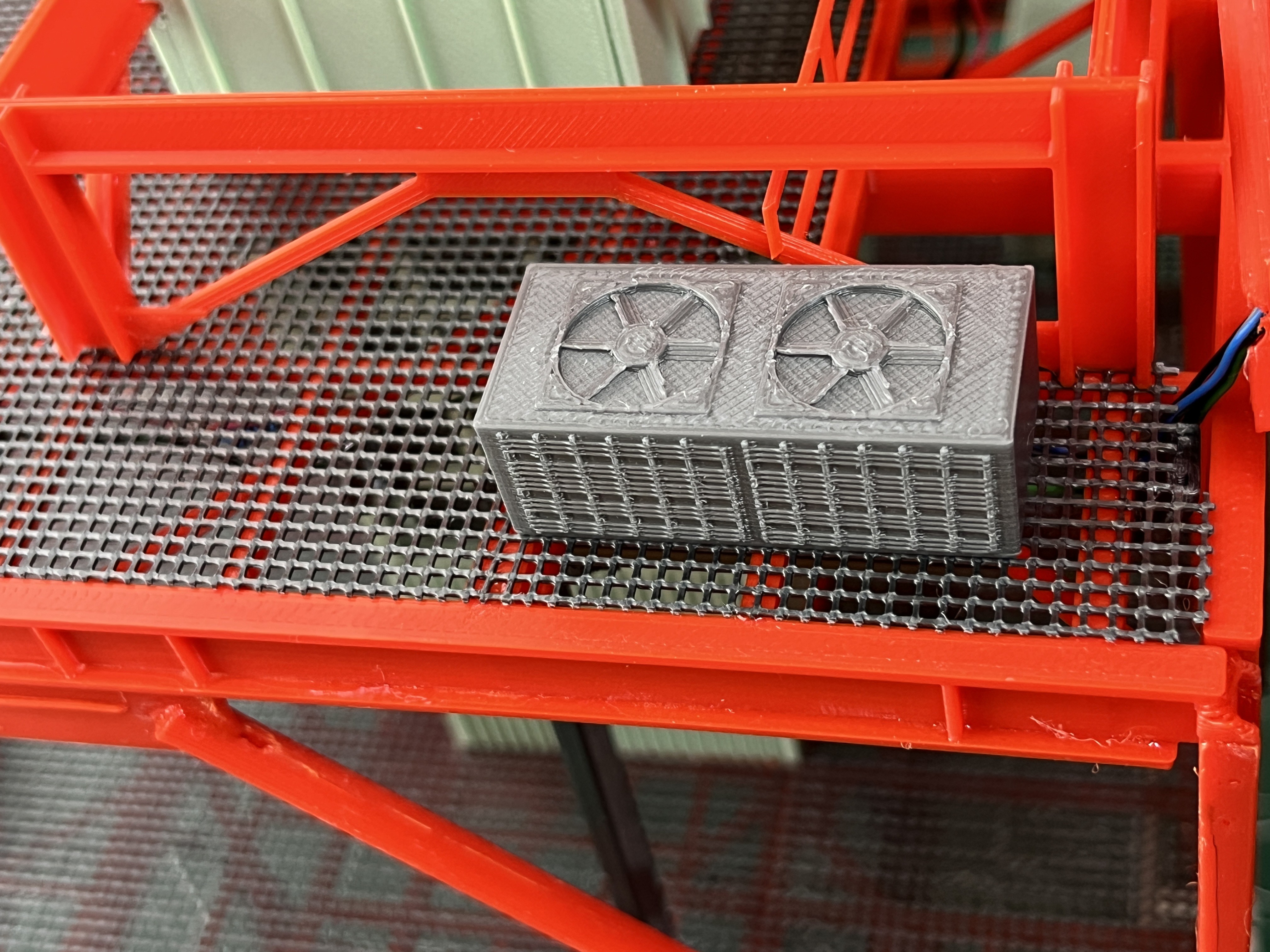
And a big shout out to Aviator67 for the great looking A/C unit.
The under room lights are on. I drilled holes in the side wall to route the wires.
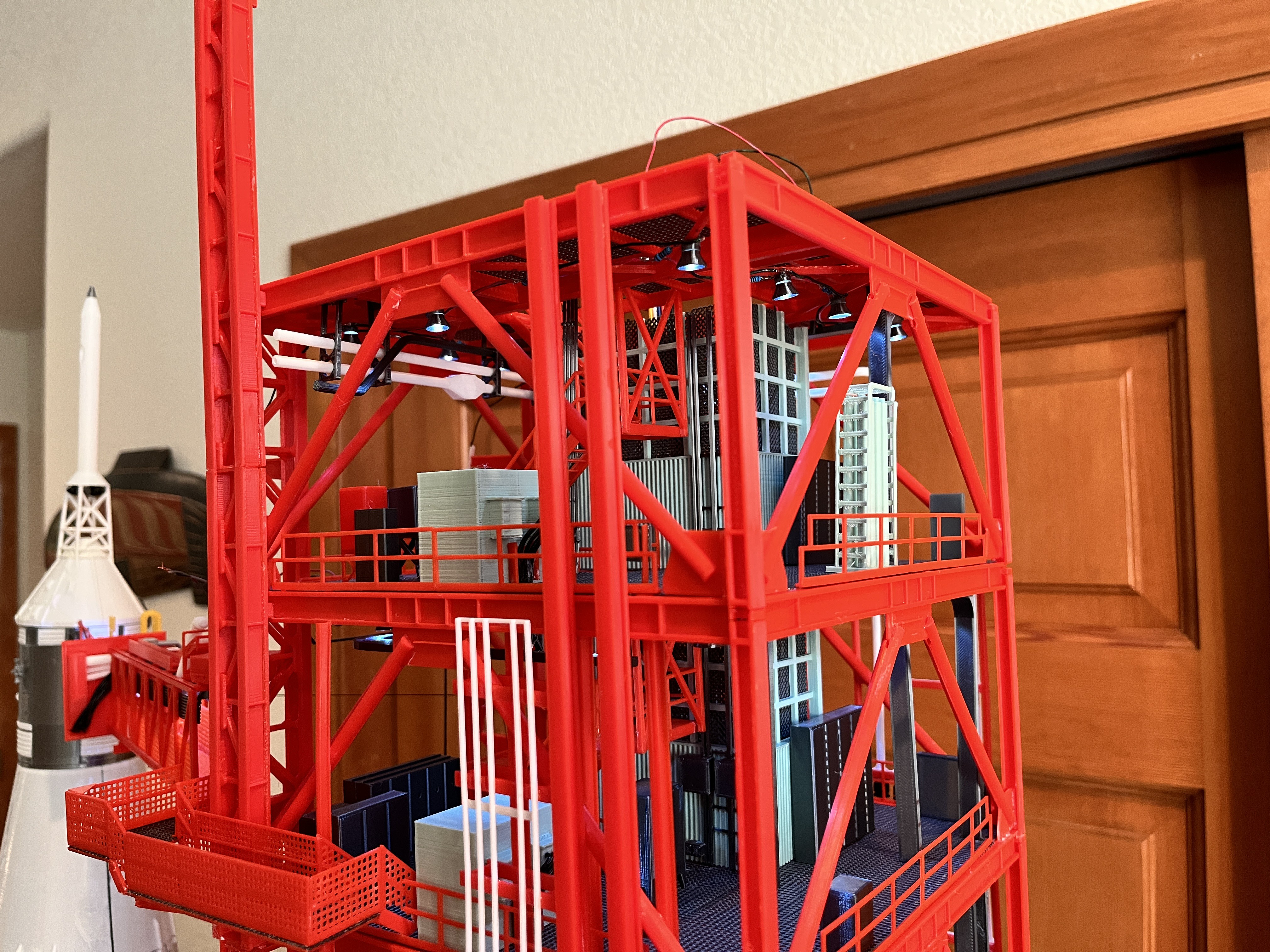
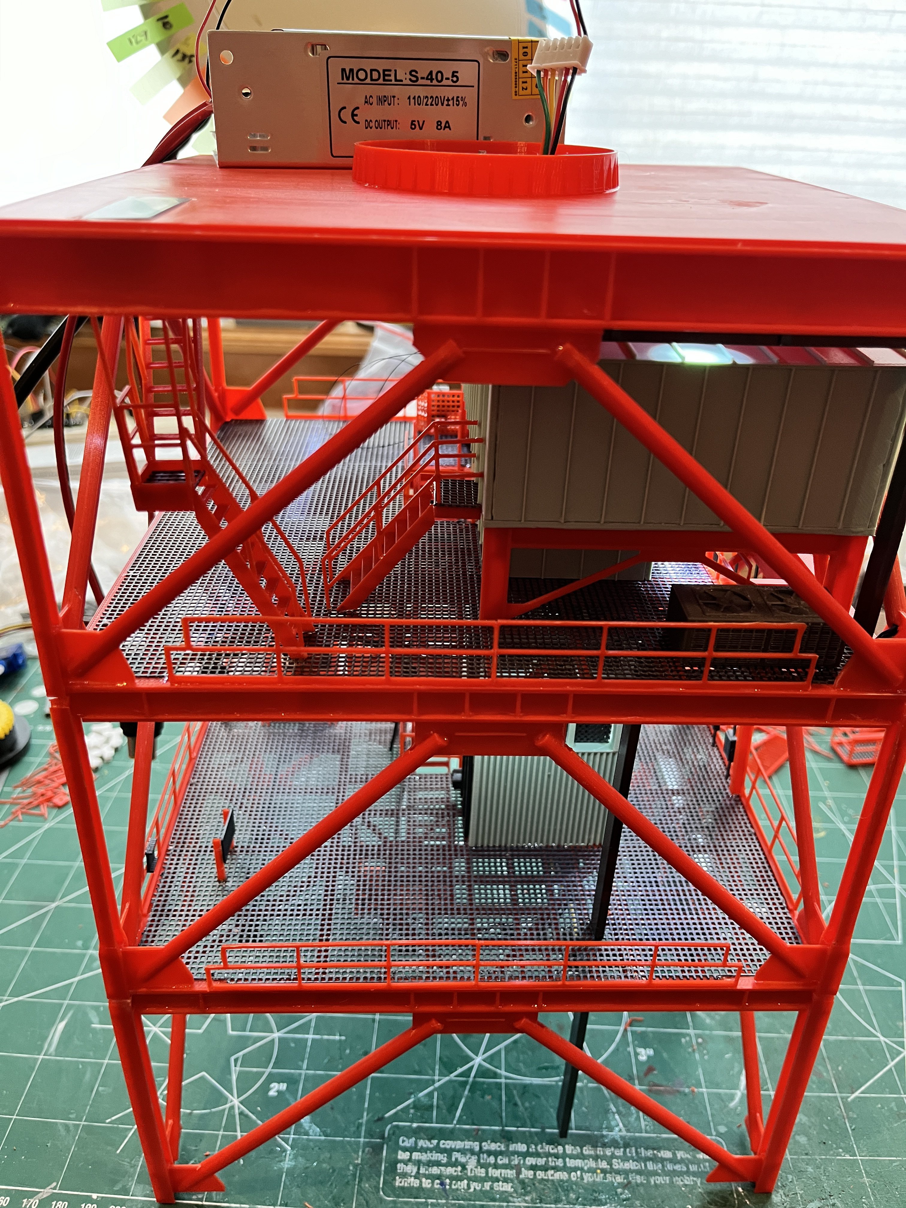
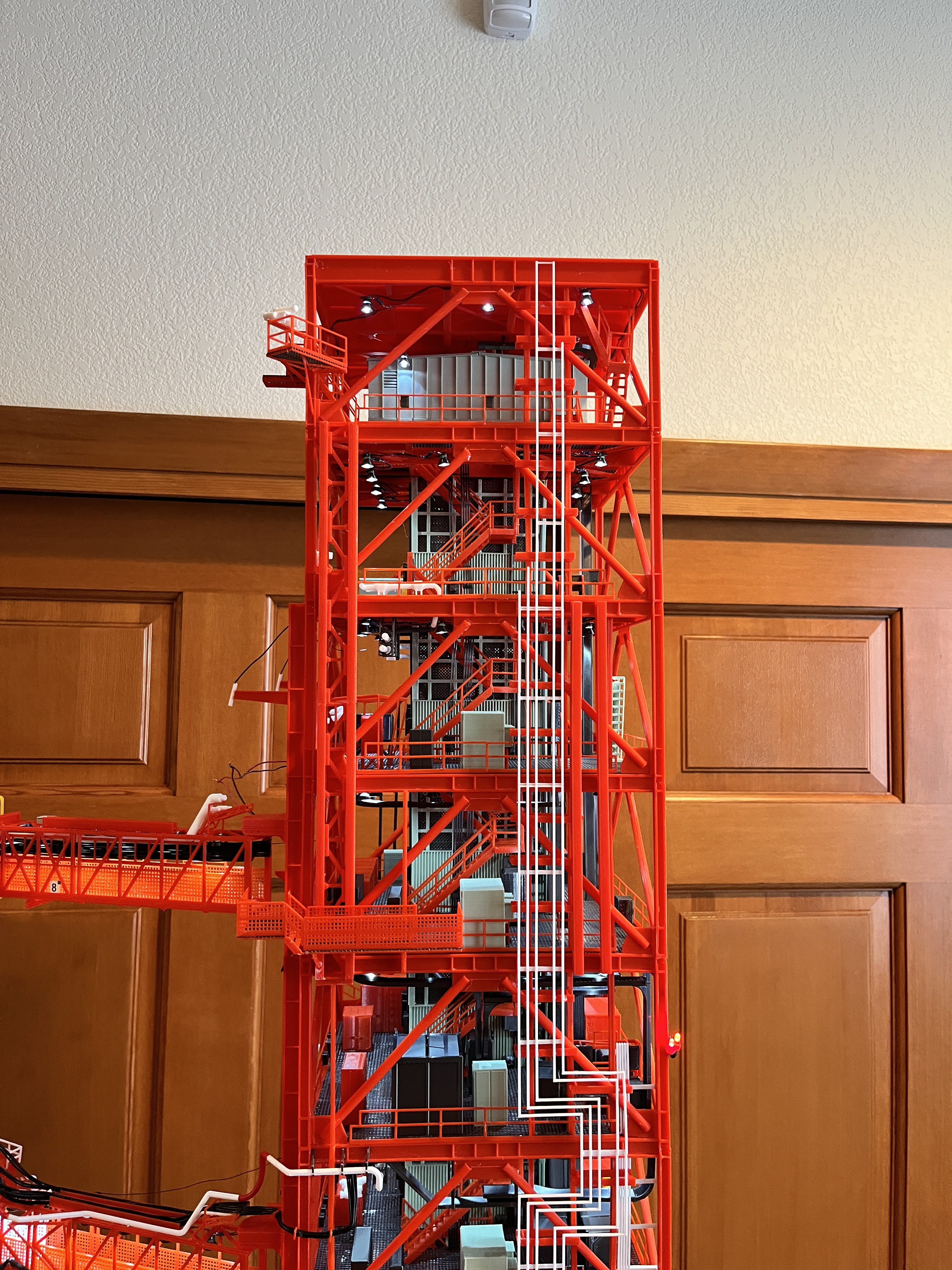
And here is the completed machine room.
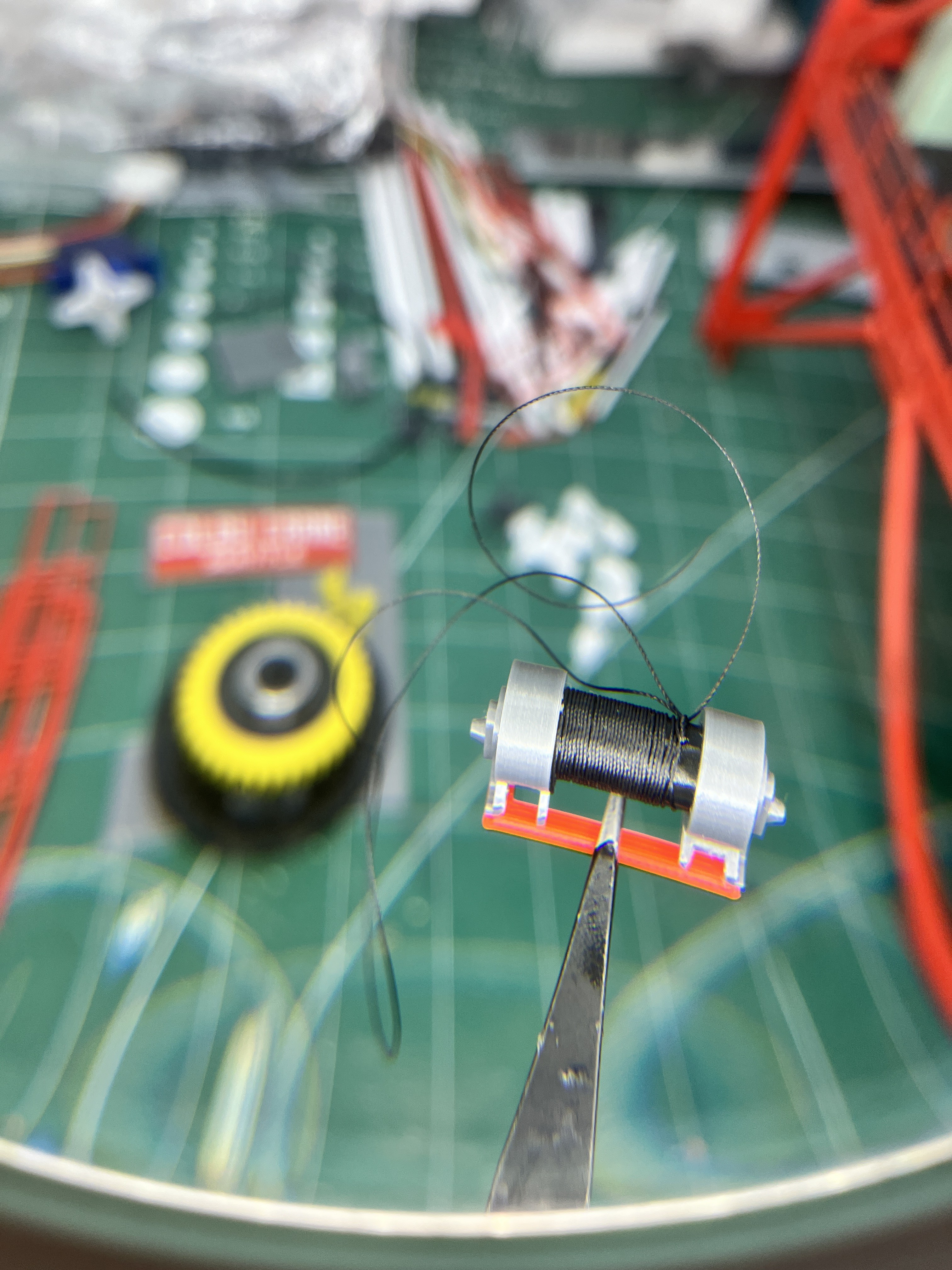
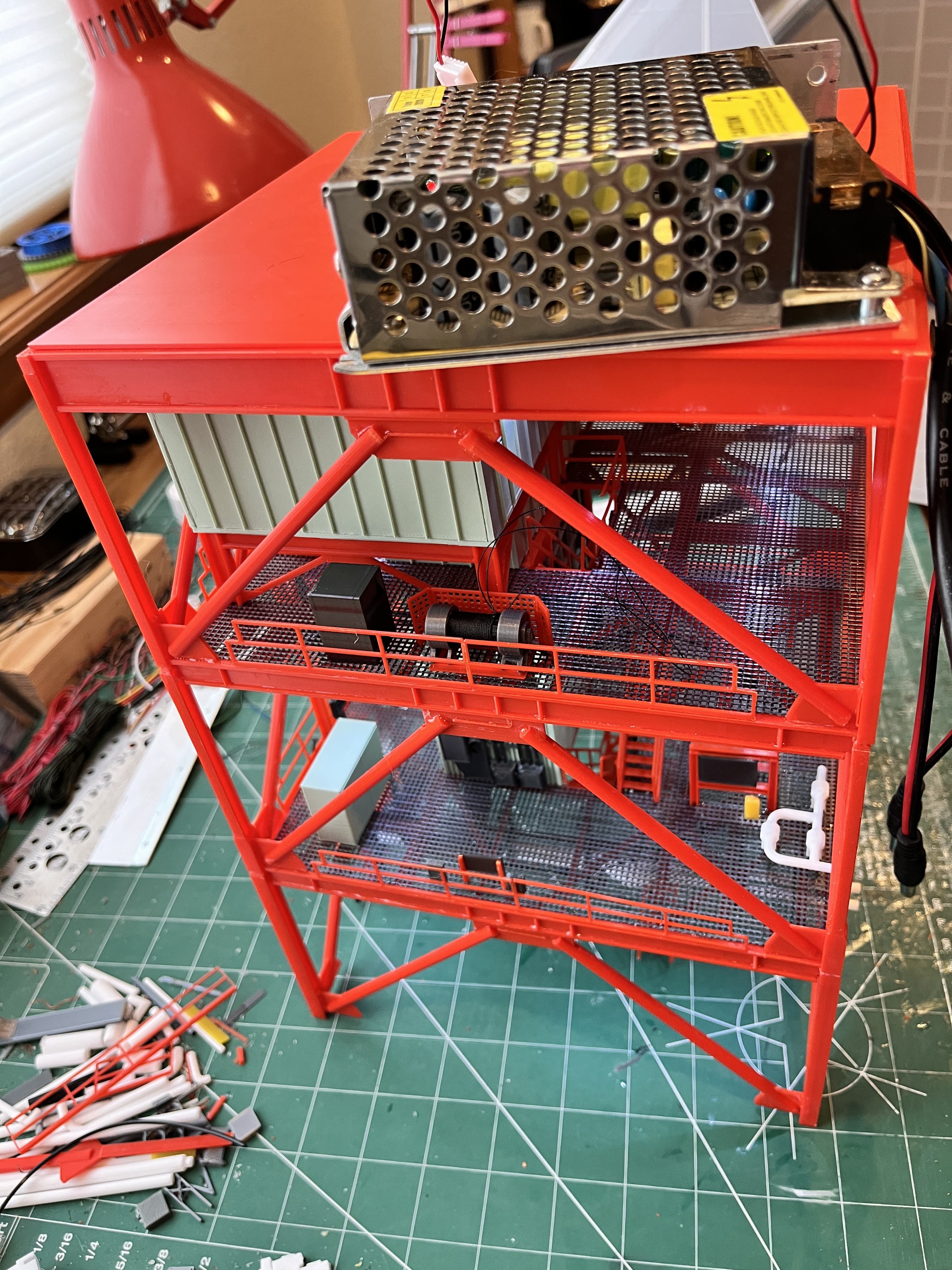
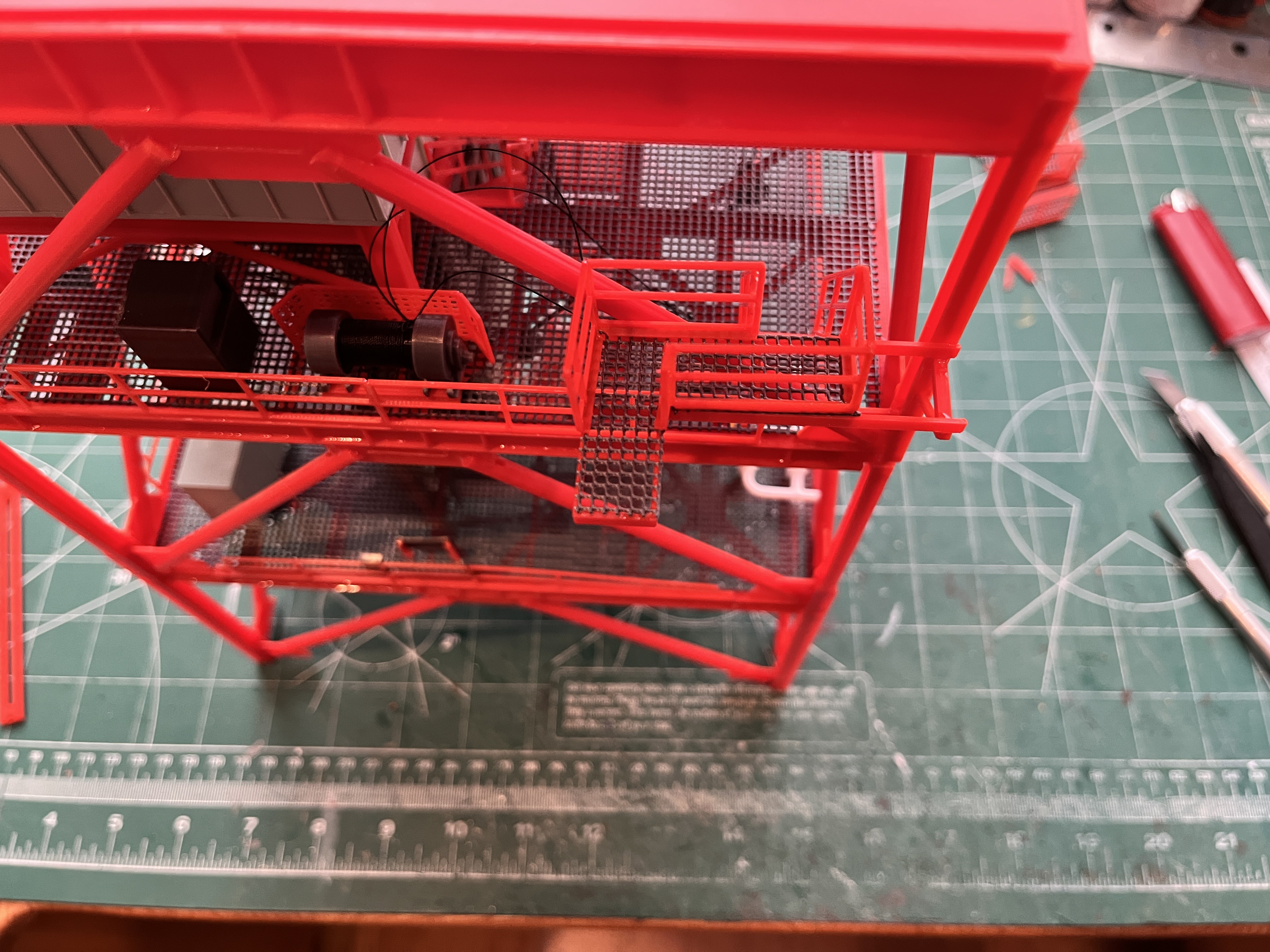
Here is the DRRS winch and control box. I wrapped the drum with the black thread I plan to use as winch cable.

Here is the L380 underfloor bracing and I-beams completed. This completes the structure all the way up. I still have to glue on this floor but first I need to add the lights.

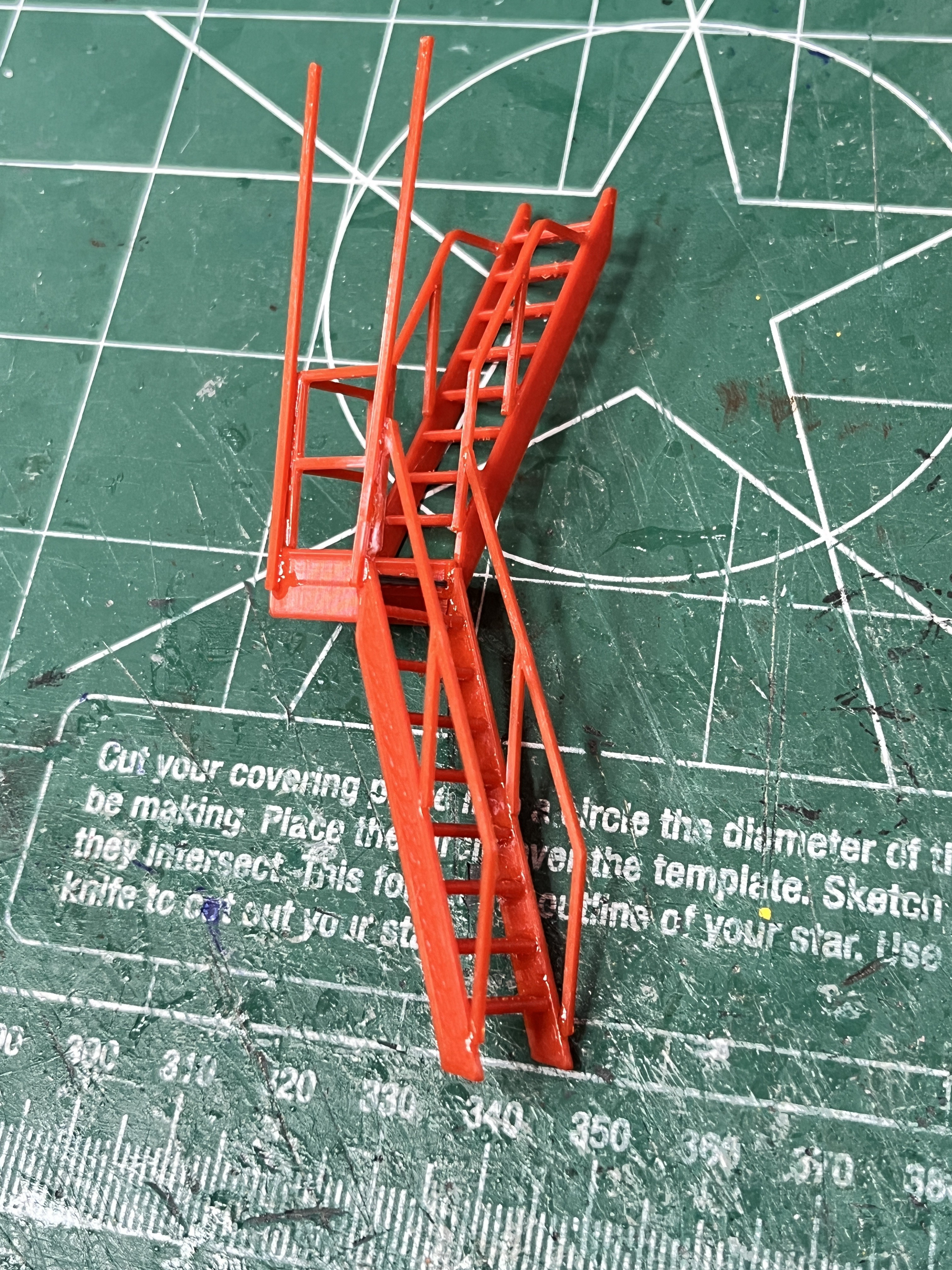
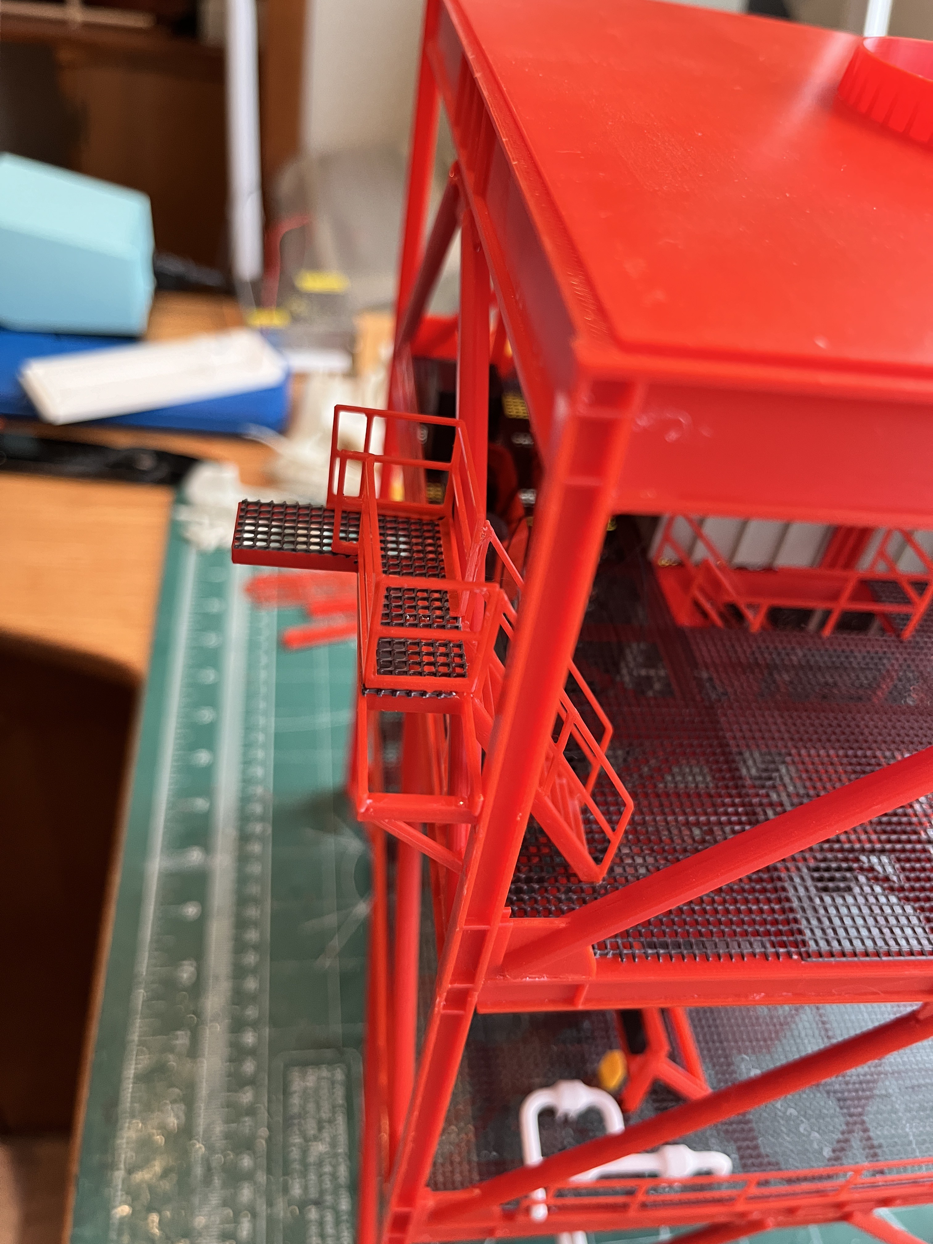
Here are the stairs going up to the crane. There is a DRRS access platform which I will add to the stair model and then the stairs will be complete.
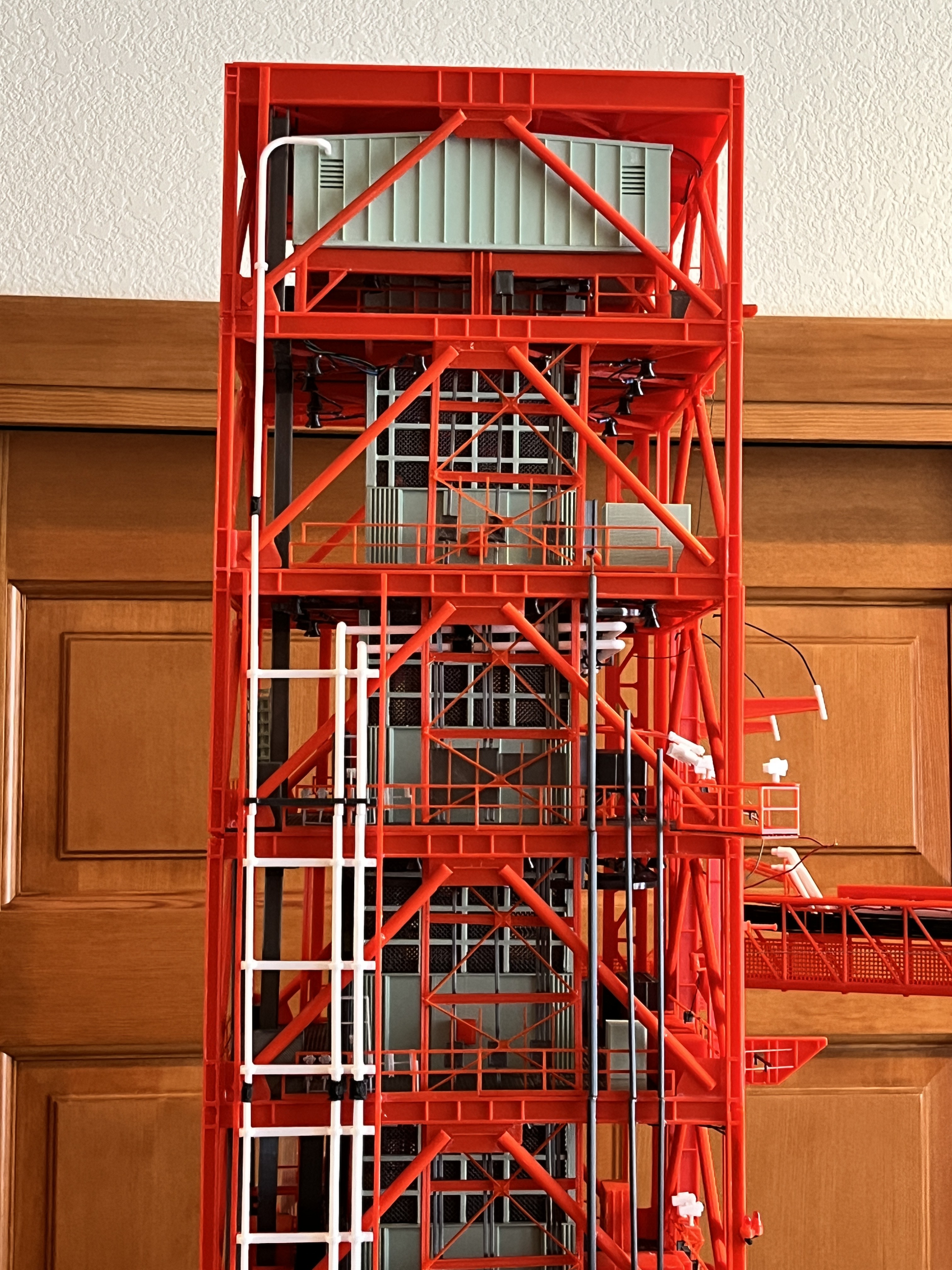
The structure is now complete. You can see in the underside of L380 I used wires that blend in since this underside area is fairly visible.
The top is ready to accept the crane.

The wires from L360 to L380 are in left side 12" cross brace.
And here are sides 1 and 3 with the lights under test.
Here is the DRRS Access Platform. Since I added this to the stairs model, the stairs are now complete.
The cameras are now complete. I might have missed a few. At some point I need to do a complete survey and add any I might have missed.
Section 7 side 2 is now complete which means the entire tower's side 2 and side 3 are complete!

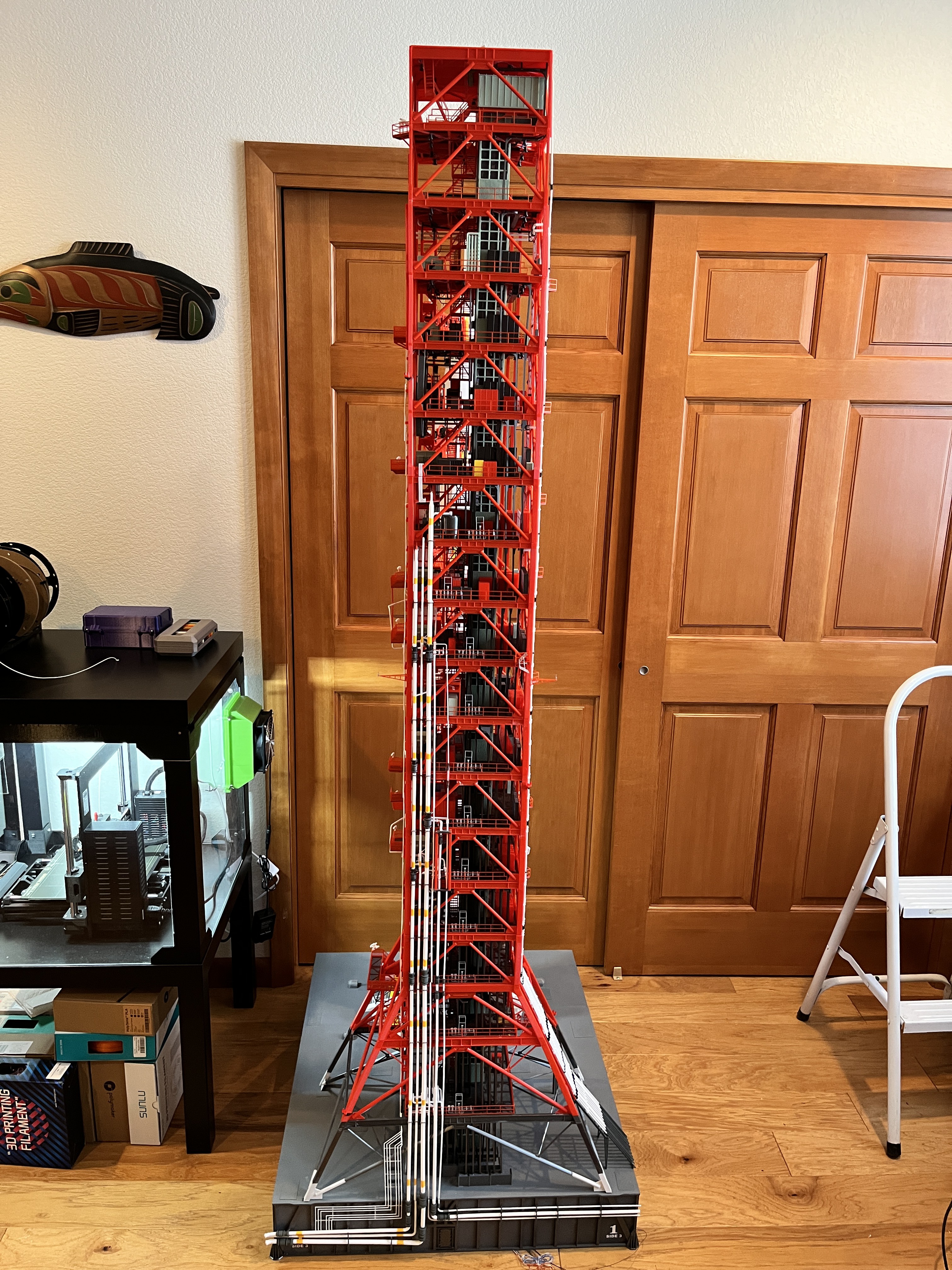
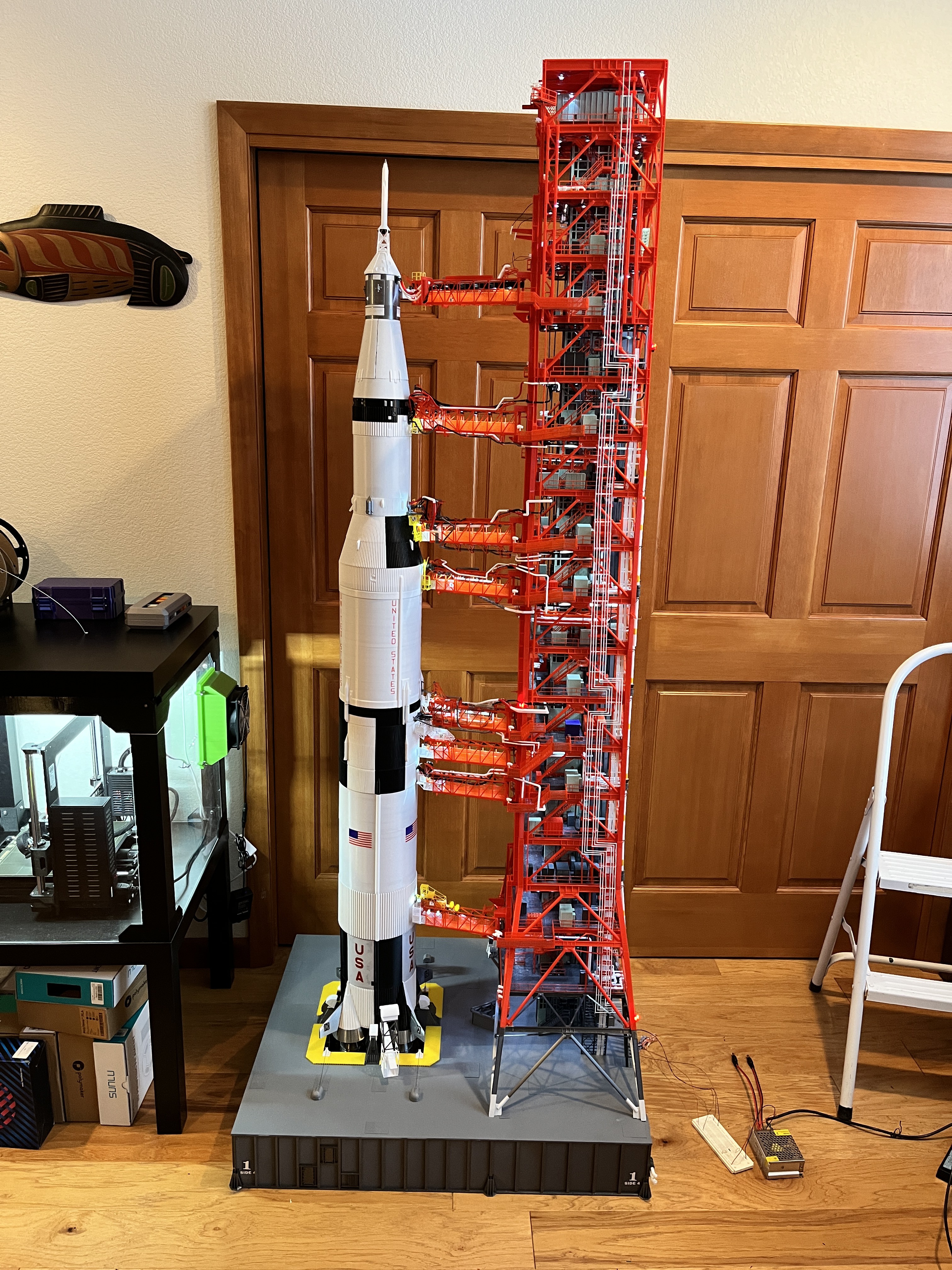
The pipes on side 4 are now complete! Now I will go back and complete the parts for the Launcher and then its on to SA #9, the DRRS and the crane.
Discussions
Become a Hackaday.io Member
Create an account to leave a comment. Already have an account? Log In.