The Colby crane is the final, crowning achievement of the LUT. The crane is going to be automated in that it will rotate and the hook will raise/lower. Notice that I intended to use the crane model by CristineZ as is but the more I dug into it the more I realized how incorrect various aspects are. I will attempt to use as many of these parts as possible but if the part is incorrect I will redesign and publish the new part.
A question was asked on the space-models forum about a flashing light on top of the model, which would have to be on top of the crane. Here is GTGeo's response:
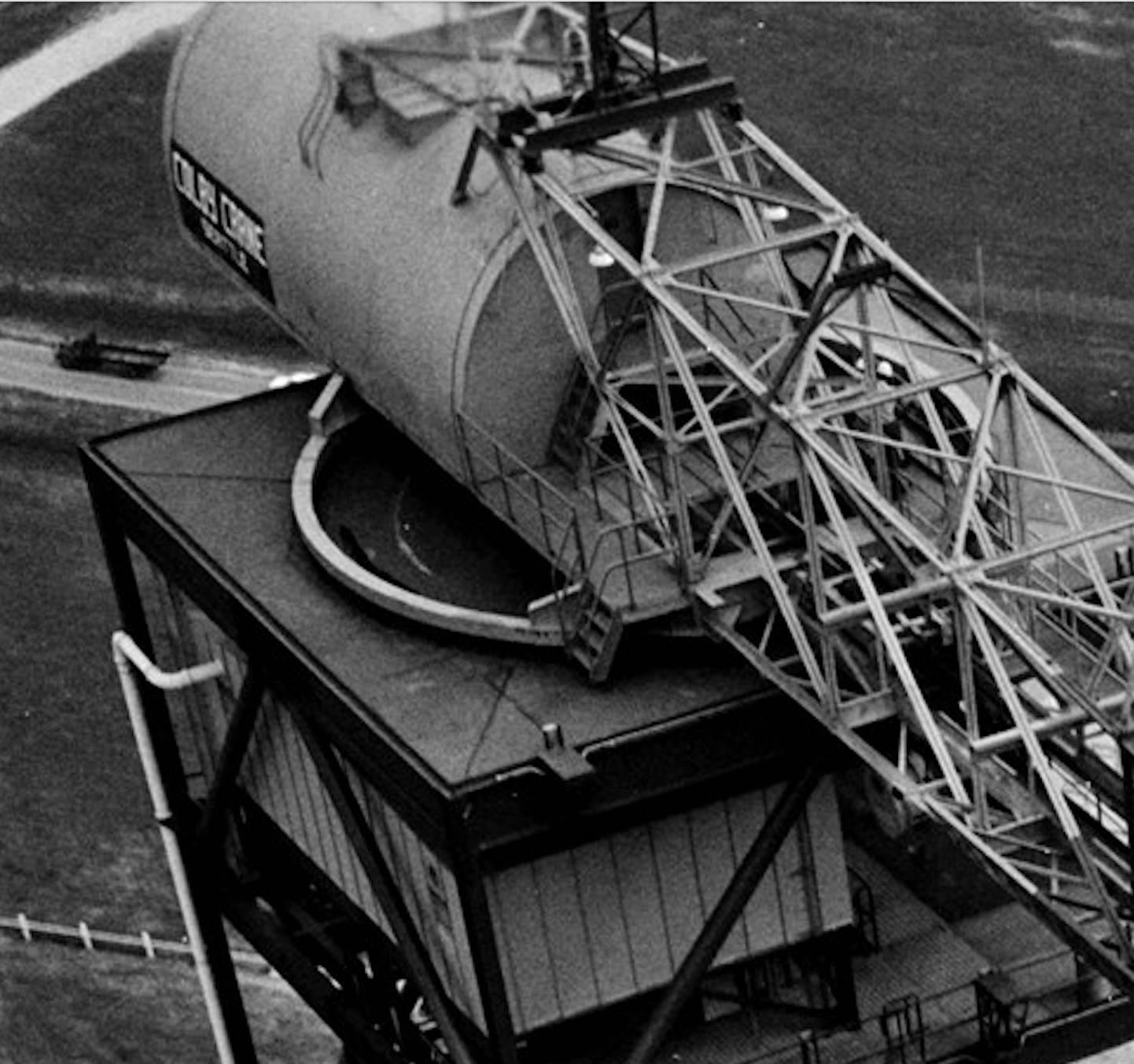
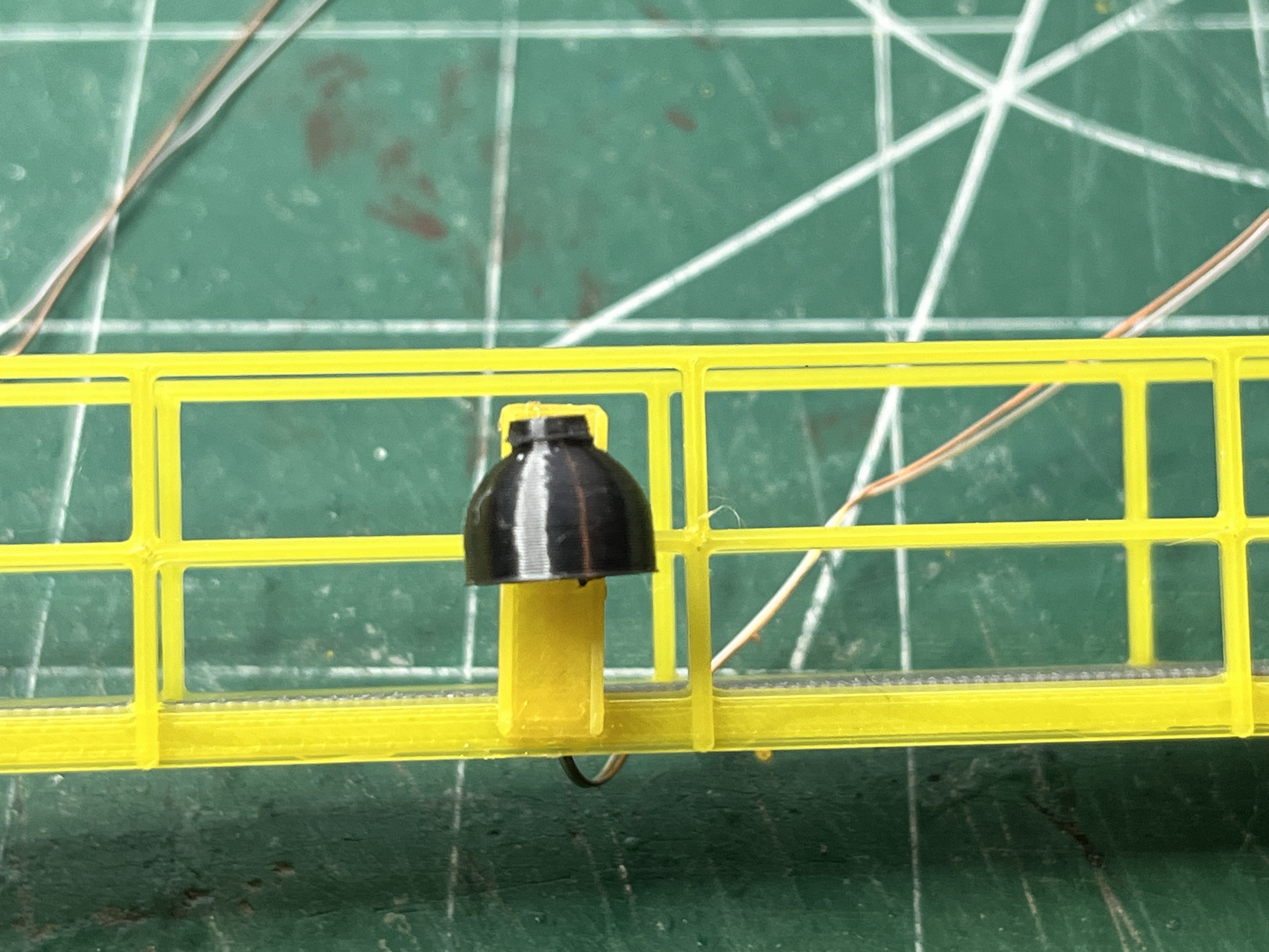
The top of the lightning mast had a light and there was a Crouse-Hinds FCB-12 flashing beacon on top of the crane above the door to the machinery house.
Ahh, a vintage airport beacon. I will have to model that. I was wondering what that thing was. I was unable to upload the manual but a quick internet search shows two lights inside a round fresnel lens. I am definitely going to have to get some clear PLA.
Here is my version of the beacon for the top of the crane.

Oh wait, that's not it. Here it is. I like the way the clear PLA printed up as a fresnel lens. I may re-print this with a darker grey.
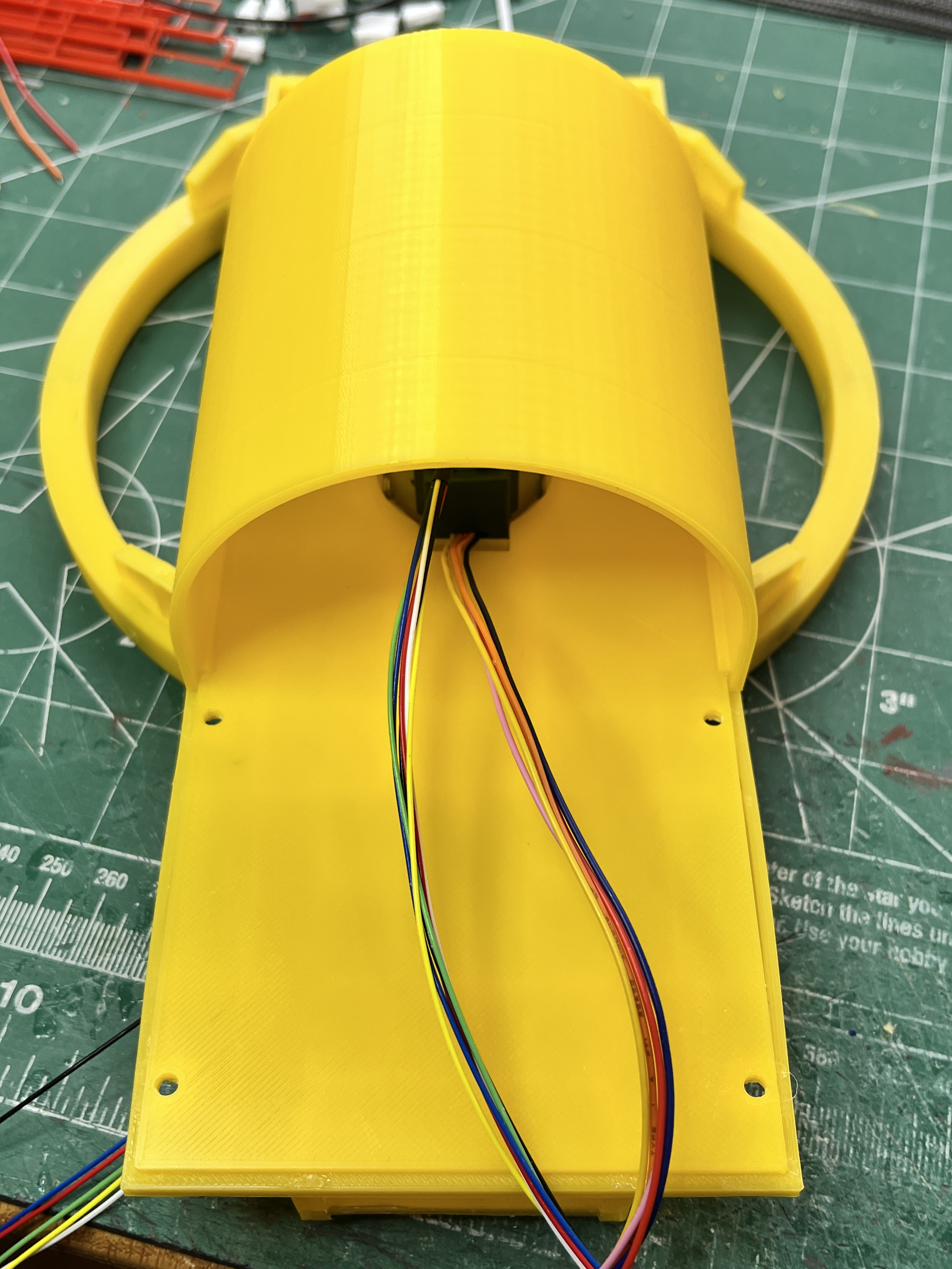
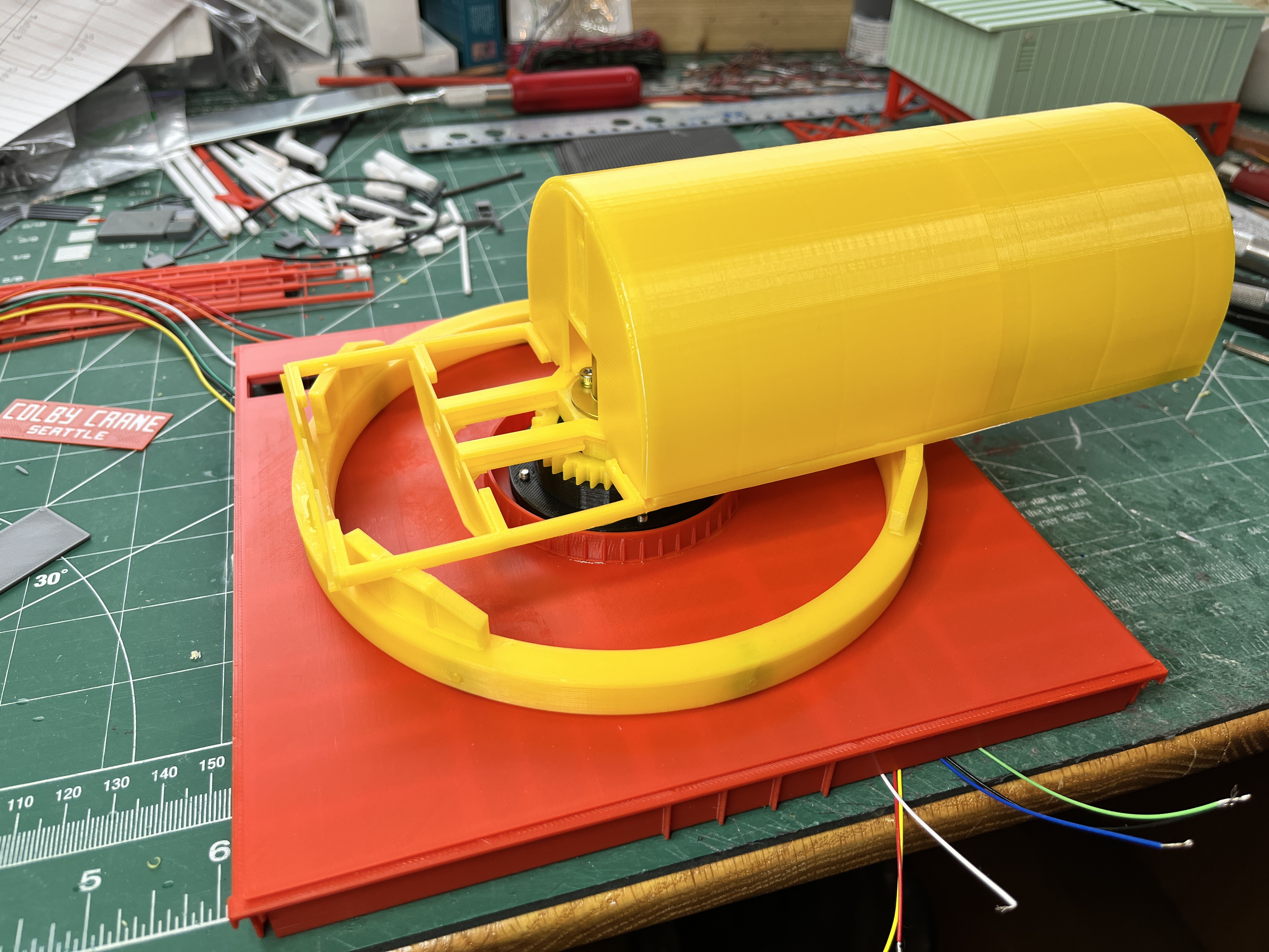
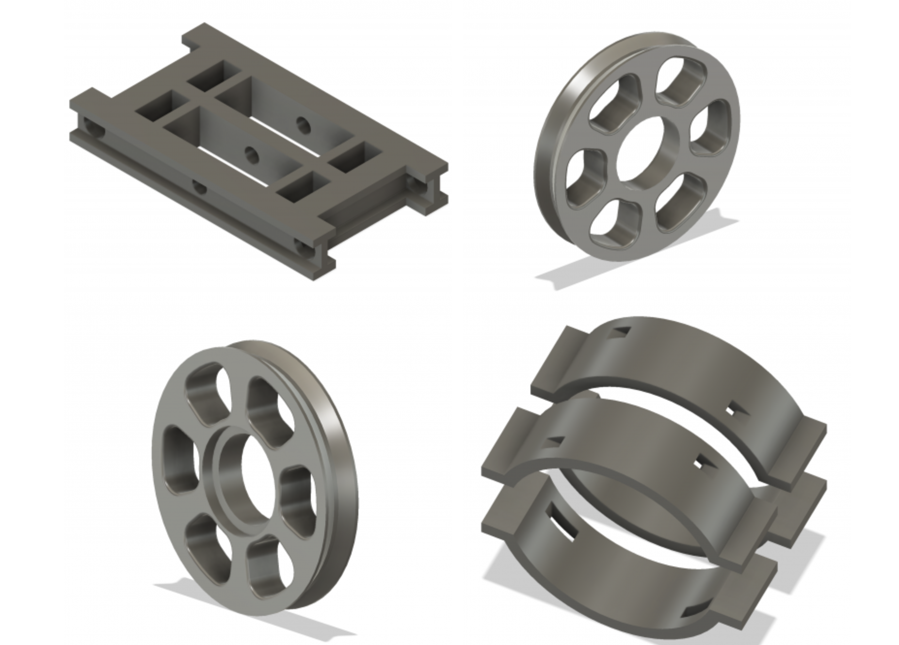
New crane automation design: The old design, using two continuous servos, was proving to be a bad design. The servo will work well for the winch motor but not to rotate the crane. To get the speed down low enough, from 110 RPM to something reasonable was requiring too many gears and modifications to some of the underside carrier beams. After sleeping on it I have redesigned the crane rotation using a fairly standard micro stepper motor. This motor (28BYJ-48) is small but has internal gearing to get it down to 15 RPM. The redesign uses the same Kingpin with a 36 tooth gear versus 48 tooth gear. No idler gearing is required. A 12 tooth gear will press fit onto the motor shaft. This gear combination will get the rotation down to 5 RPM. The stepper motor is large enough, 28mm diameter, that I had to redesign the I-beams that run under the floor. The motor mount that holds the stepper motor and slip ring will notch into these I-beams. Carrier beam #3 gets moved out a bit to make room but none of these cross beams have to be redesigned and this beam is within the large outer main roller base so the fact that it has moved will hardly be visible. This design will be more compact, stronger and more elegant.
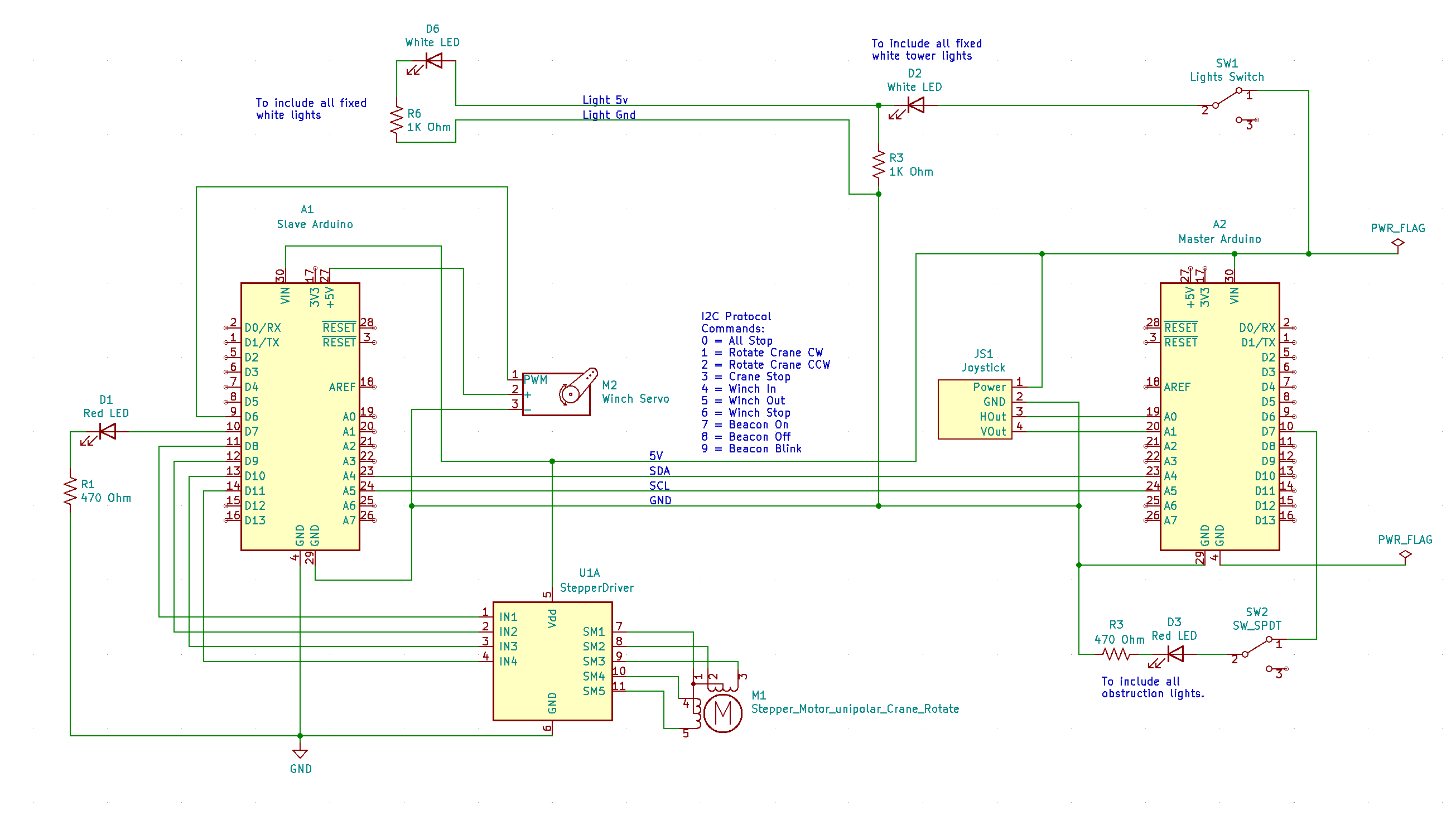
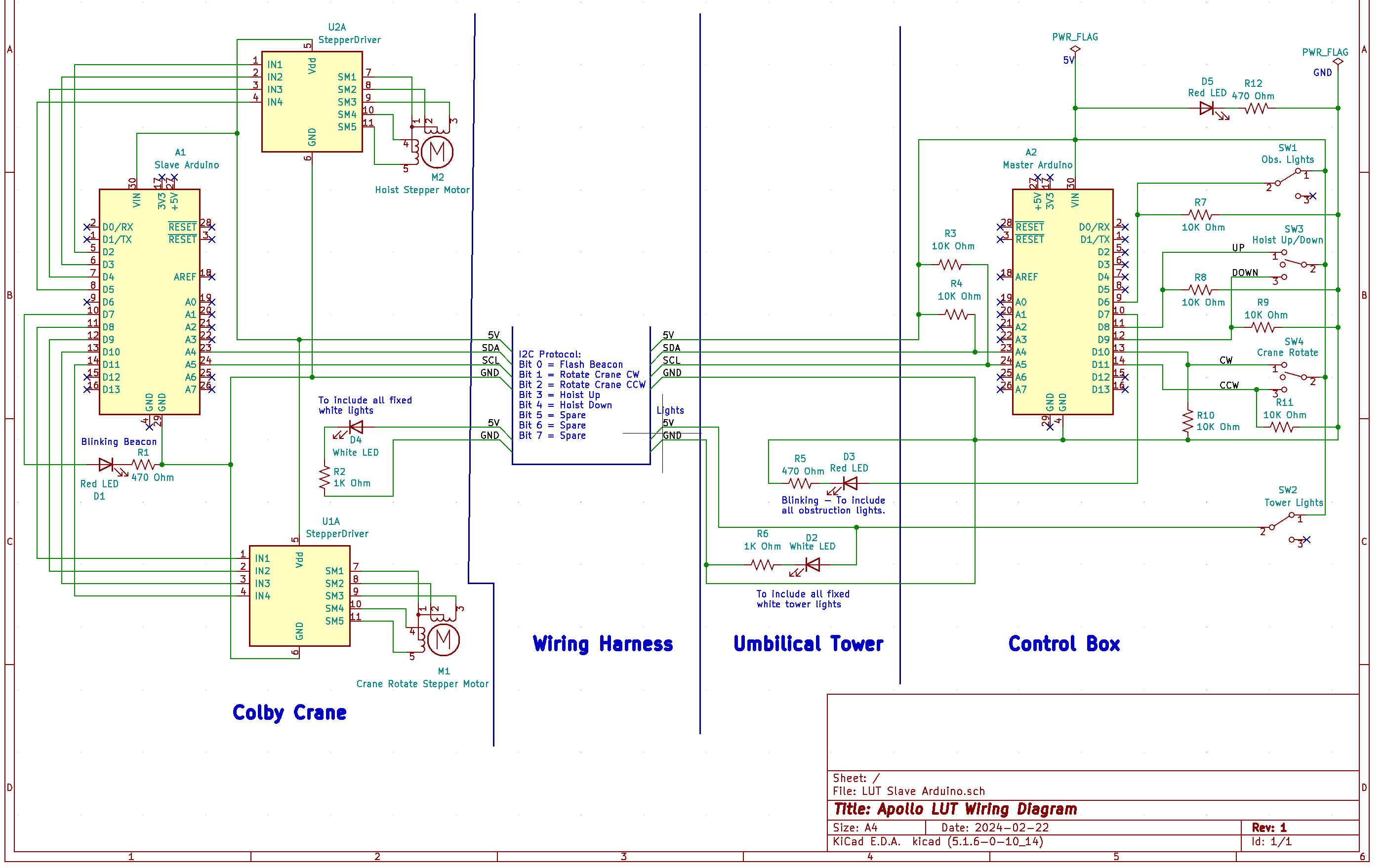
And now for the more interesting part of the redesign. There are six wires going into the crane with two of them already dedicated to the fixed lights. That leaves four wires for the automation. A stepper motor requires 4 wires to run with another two for power, one for the servo and an additional two to flash the top beacon. The solution that I have had in my back pocket all along is to put a slave Arduino inside the crane. To run the slave Arduino using the I2C protocol requires 4 wires, power, ground, SDA and SCL. I will create a simple protocol where a one byte command is sent, giving 256 possible commands. Currently I can think of 10 commands; all stop, rotate crane clockwise, rotate crane counterclockwise, crane stop, winch in, winch out, winch stop, beacon on, beacon off and flash beacon. This is similar to the protocol I built for my Mars rover project. The one bit of caution I read about is that the stepper motor should be connected directly to the power source and not have its power routed through the Arduino. Fortunately all of these parts run using 5 volts.

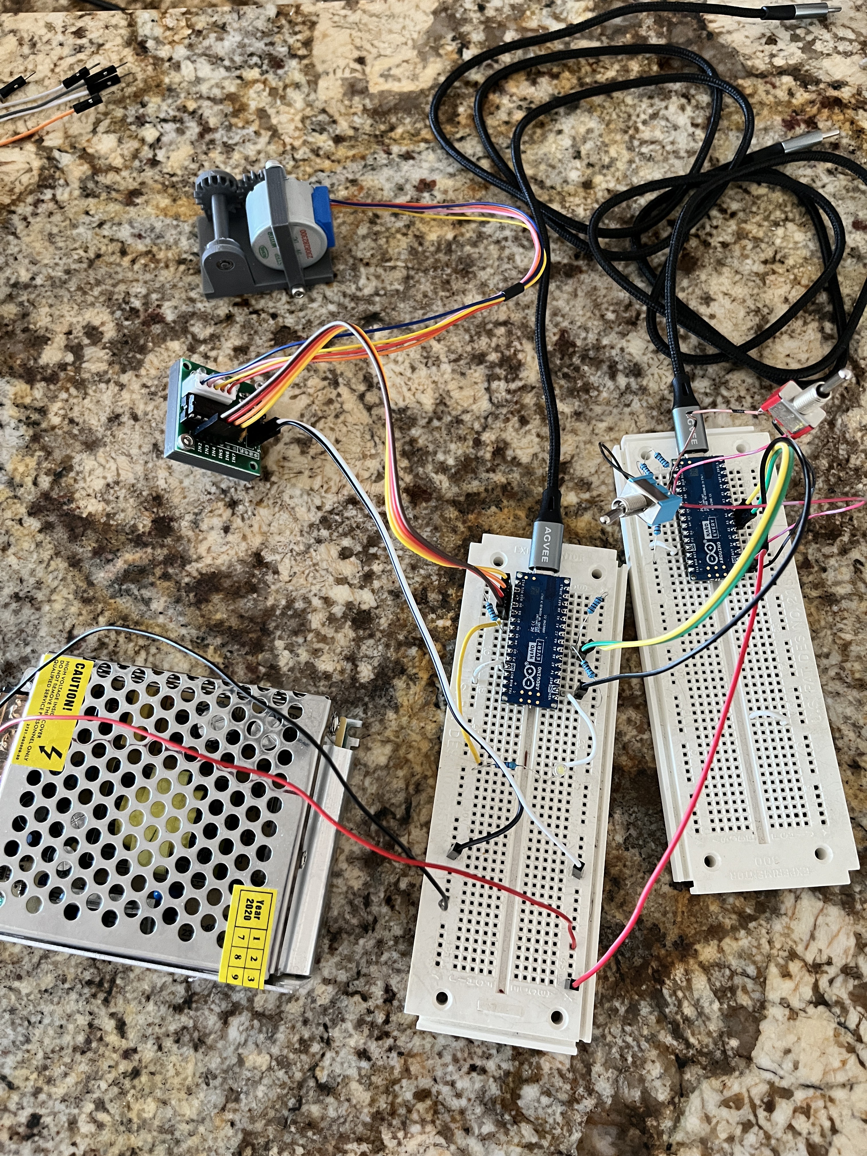
Here is a first cut at a wiring diagram. All the individual capabilities have been tested out using a single Arduino. Now to write the code to get things split between two Arduinos and get all the functionality driven via software interrupts.
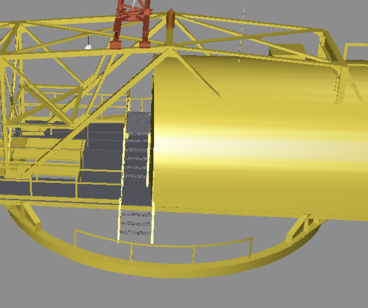
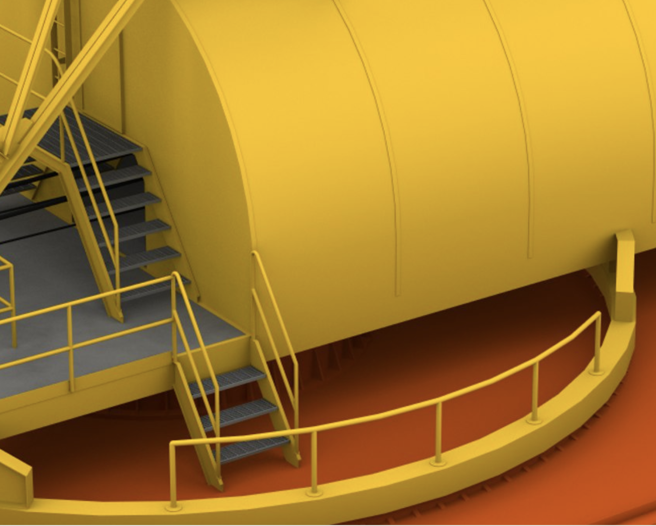
Here's a question for everyone regarding the steps on either side of the crane going down to the level 380 floor. The structural diagrams I have found so far agree with the turbo squid drawings in that these stairs come straight off the crane platform at 90 degrees. ChristineZ's version of the crane has a landing platform on each side with the stairs going down toward the rear. Any definitive answers on this?
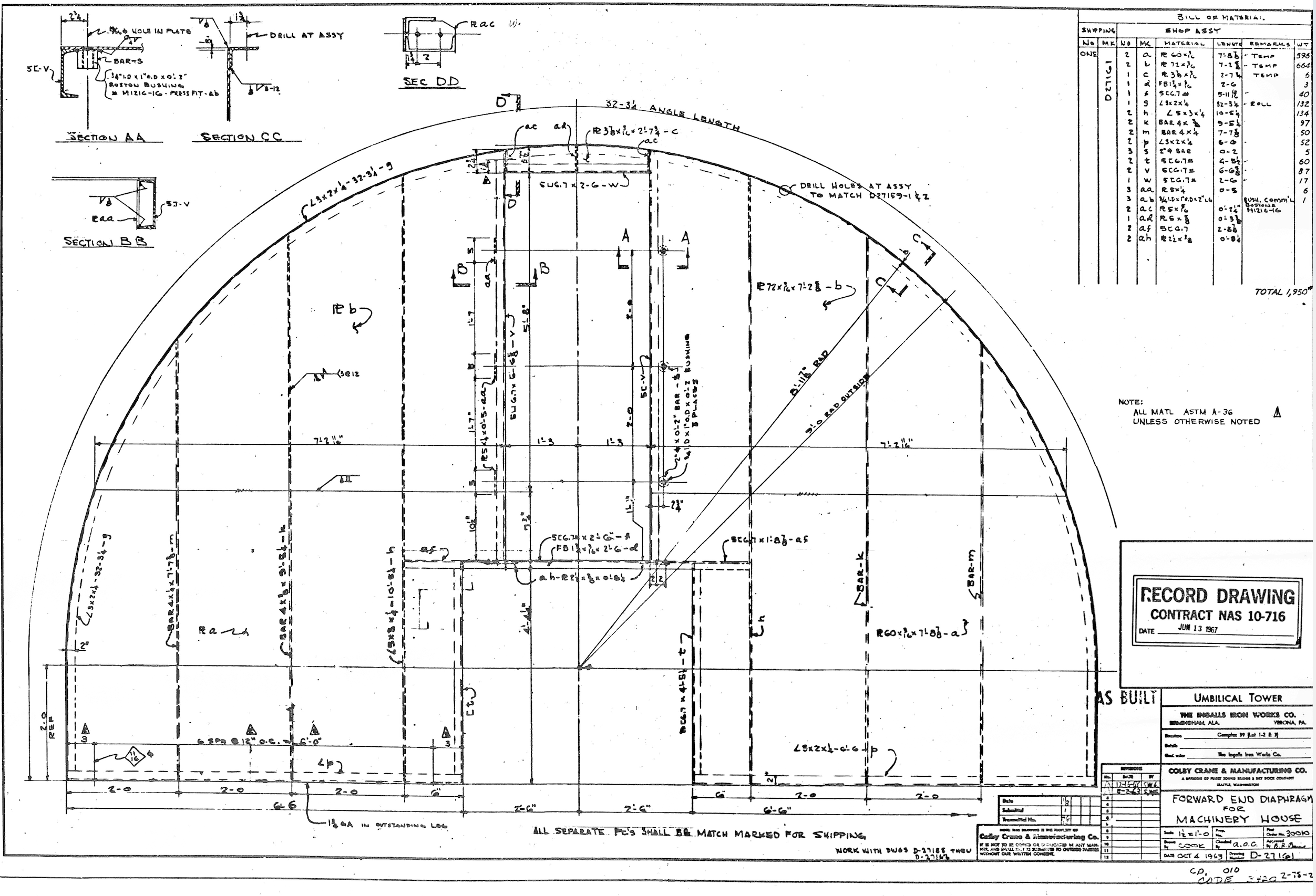
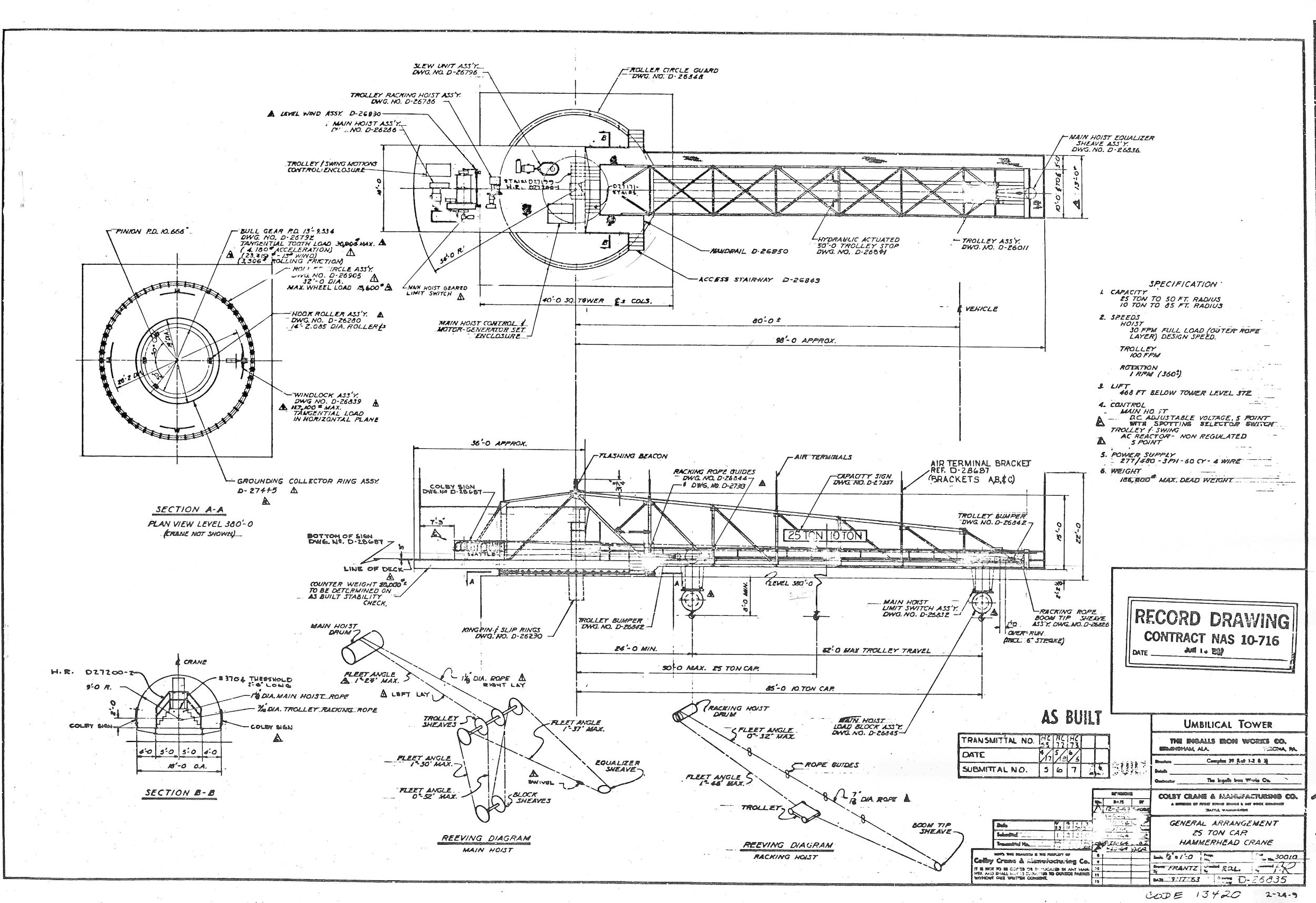
This seems to be the best drawing I have found so far. It shows the stairs going off at 90 degrees and just outside the rollers. The two models I have found so far show the stairs staying inside the rollers.
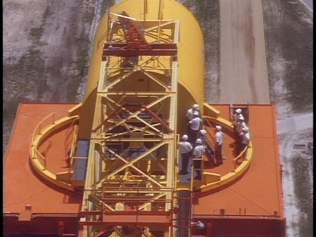
And what do y'all think of this??? This picture of the crane in the museum shows clearly a platform on top of the crane that is not part of the ChristineZ model or turbo squid.
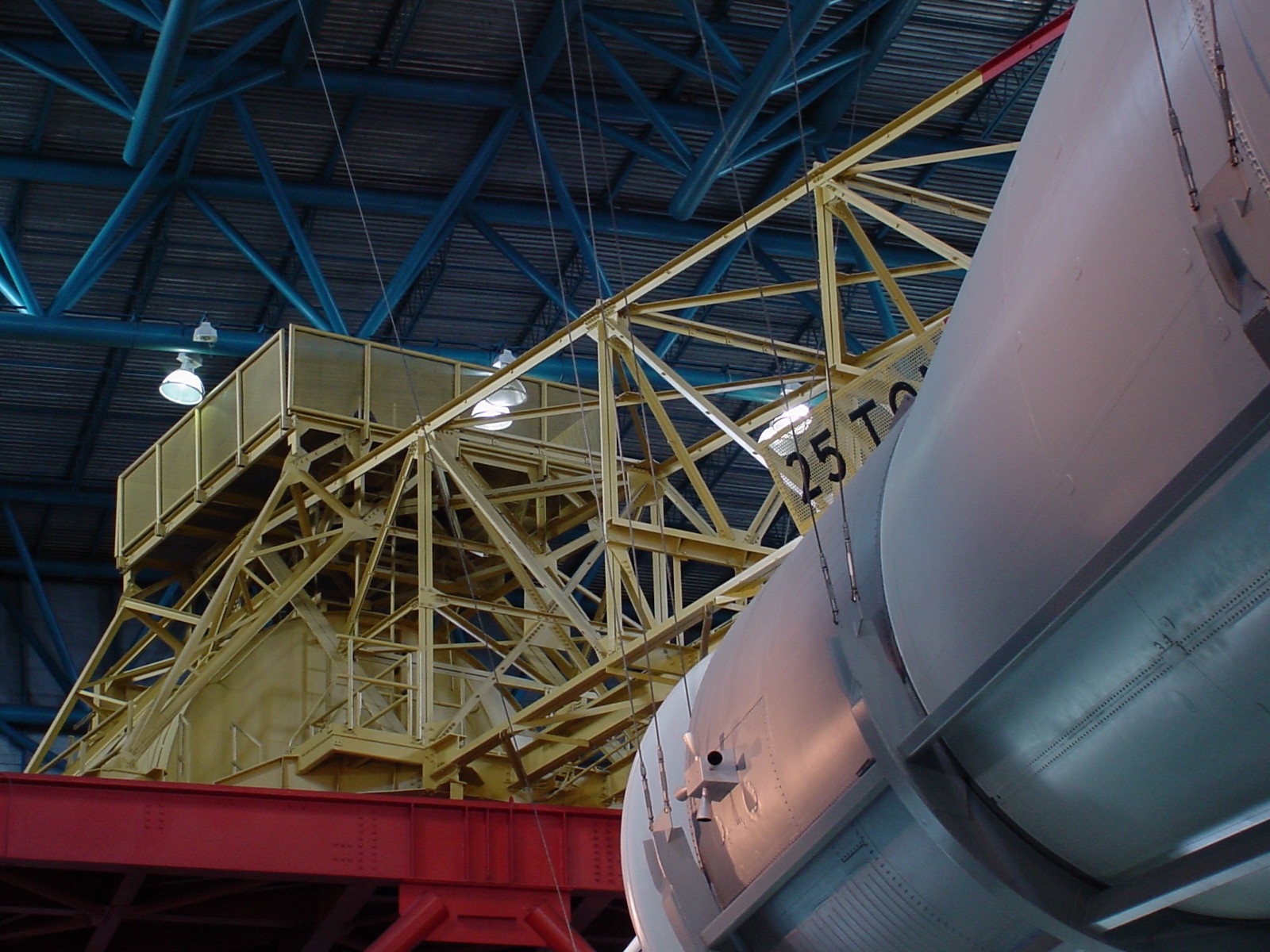
And sure enough, here is a drawing of this structure. And what's on top? The beacon.

OK, here is what I consider definitive proof about the stairs. You can see on the zoomed in screen shot there is no side landing, the stairs come straight off the side. I will redesign these side stairs to match this. You can also see in this picture (which matches turbo squid) that some of the parts in the ChristineZ model are not the correct color. The tower catwalk and tower riser should both be red.

At some point they must have added that additional platform on top. I'm going without this added platform.
I also did some quick measurements. Each of the 6 end sections are 13' 2" long which is 66.89mm at scale. The ChristineZ model made each of these sections 69.44mm long which means the model is about 28mm too long. MUST... RESIST... REDESIGN... URGE... I think the model is good enough. I will redesign the side stairs and make the catwalk grating out to the end of the boom actual grating. And of course add the working lights, beacon, working winch and rotating crane. There are two winch drums; one to raise and lower the block and the other to move the trolley out and back. I will not automate the trolley out and back but make it so that the trolley can be manually moved back and forth.
And here is the response from GTGeo: That additional structure was added to LUT 1 for SA-210 as part of the new lightning arrester tower. It stayed on LUT 1 when it was used for the shuttle program.
If you are modeling Skylab or anything before that it should not be on there.
Here is GTGeo's explanation of the stairs. The Colby Crane stairs changed on LUT 1 a few times. For SA500-Apollo4 the stairs were on the outside of the ring close to the roof access door. This was considered too dangerous when the crane would swing as you could potentially fall to your death (I'm still looking for the source) so they were moved to the inside of the ring, that way no matter the direction of swing the stairs were inside the ring.
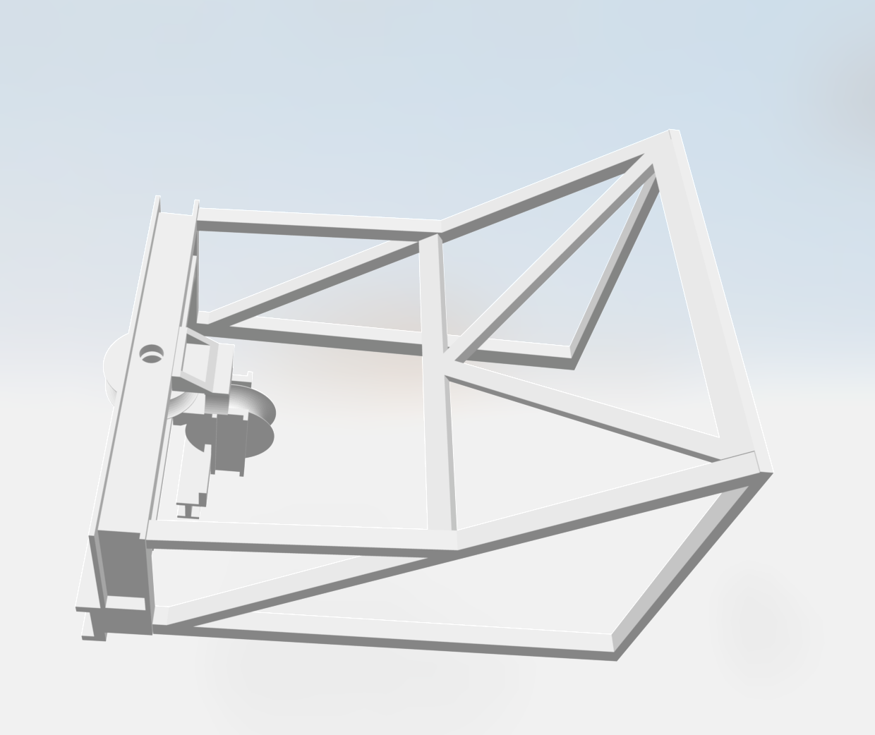
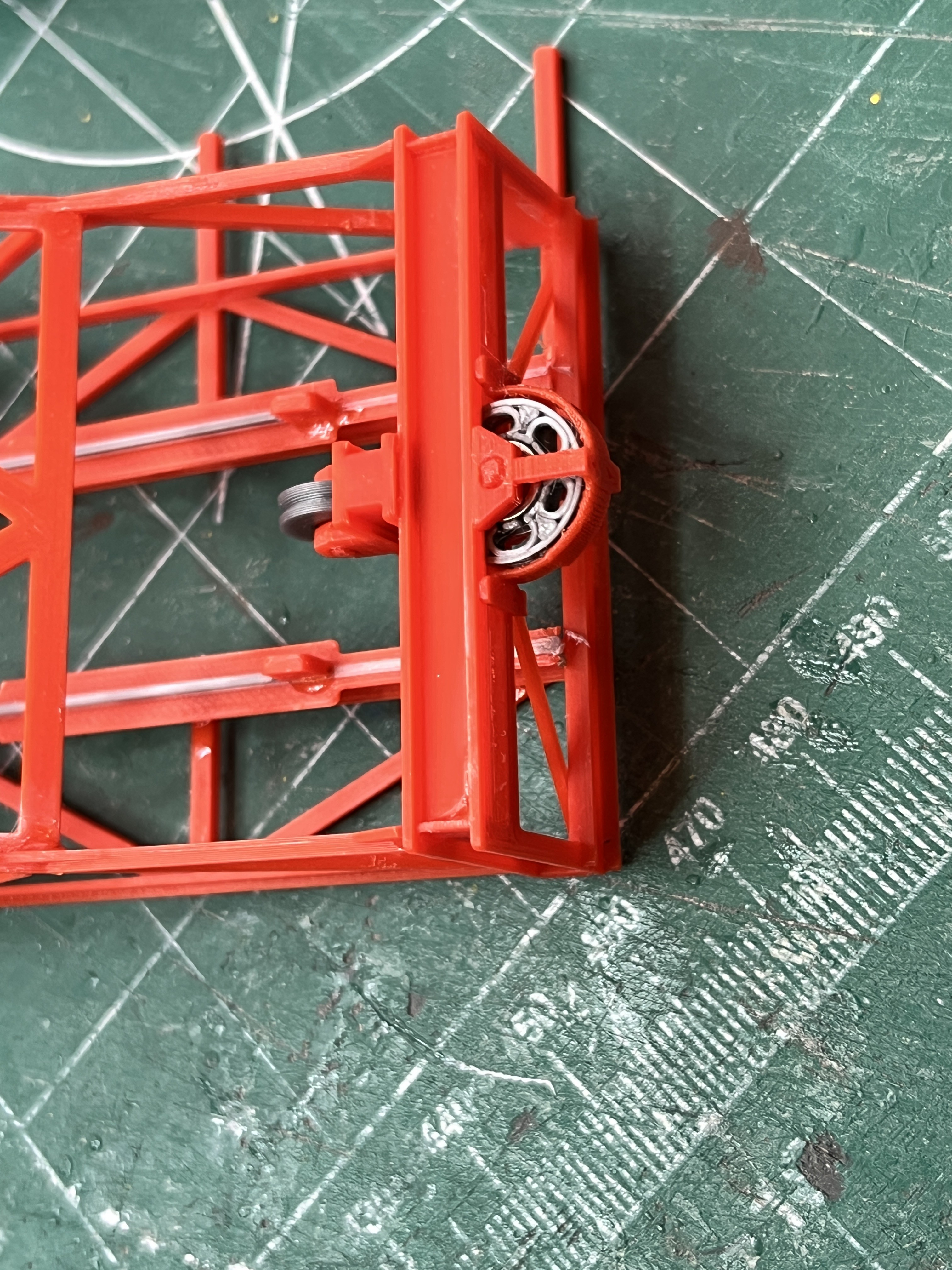
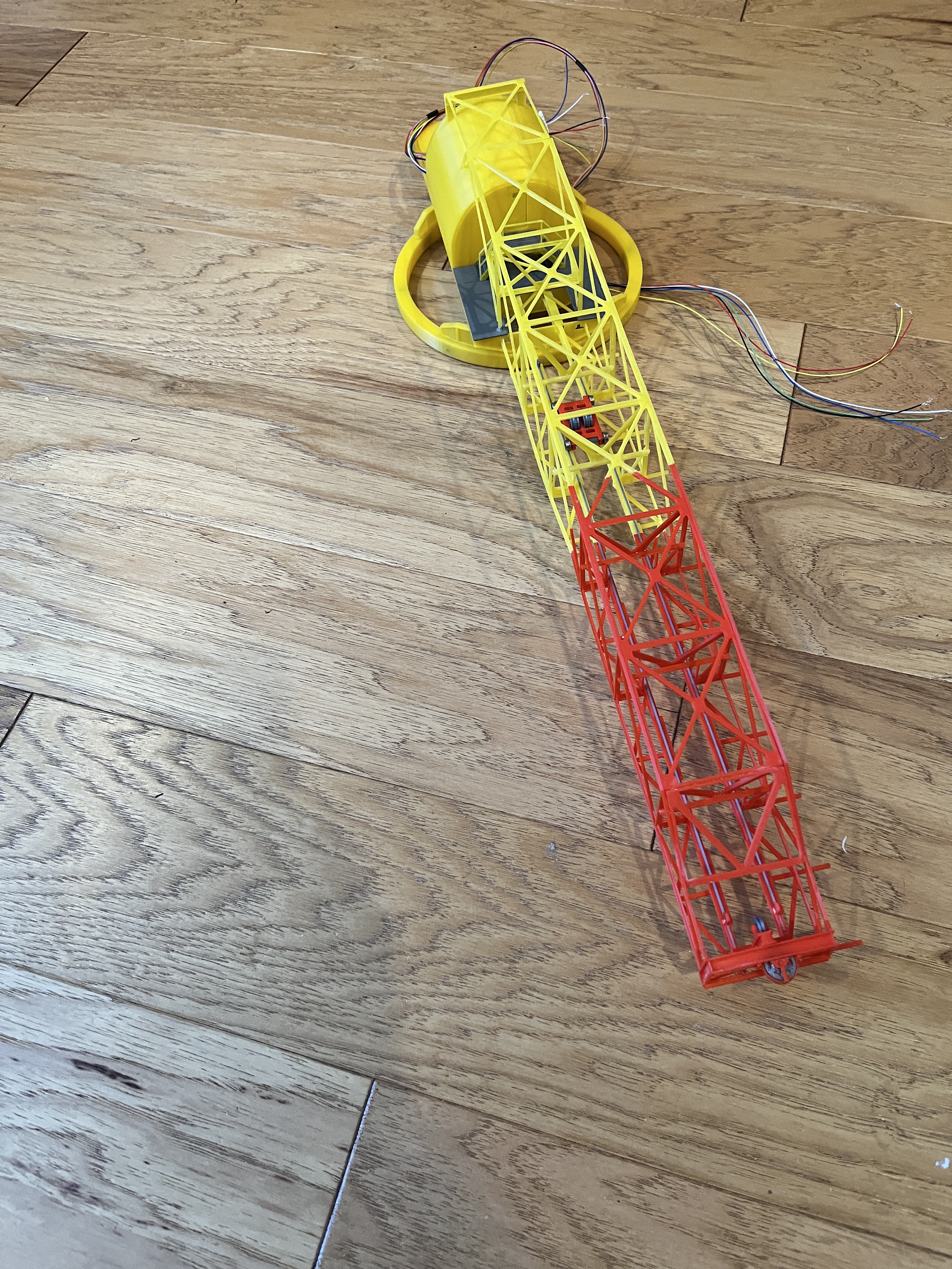
Here is a sneak peak at the new crane framework. The floor is printing now. Things are going slow with only one printer. After the floor is on there are small plates at the rear and then the weights.Yet another pivot as I narrow in on automating the crane. The earlier version of the slip ring is 22mm in diameter and it intrudes into EndA. The other issue is the wires are at least 30 gauge. The slip ring is rated at 1.5Amps which I believe you divide by 6 wires to get 250 milliamps. I found some documentation on the stepper motor and the motor draws about 240 milliamps. That is too close. And then I realized you don't really need a hole through the slip ring. The slip ring below is only 12.5mm in diameter so there is no need to redraw EndA. The slip ring is rated at 2.0 amps and has 28 gauge wires. These should handle 333 milliamps. I just need simple modifications to the motor mount and the king pin. It will take a week for the part to arrive, then I can get exact measurements of the part. More to follow...
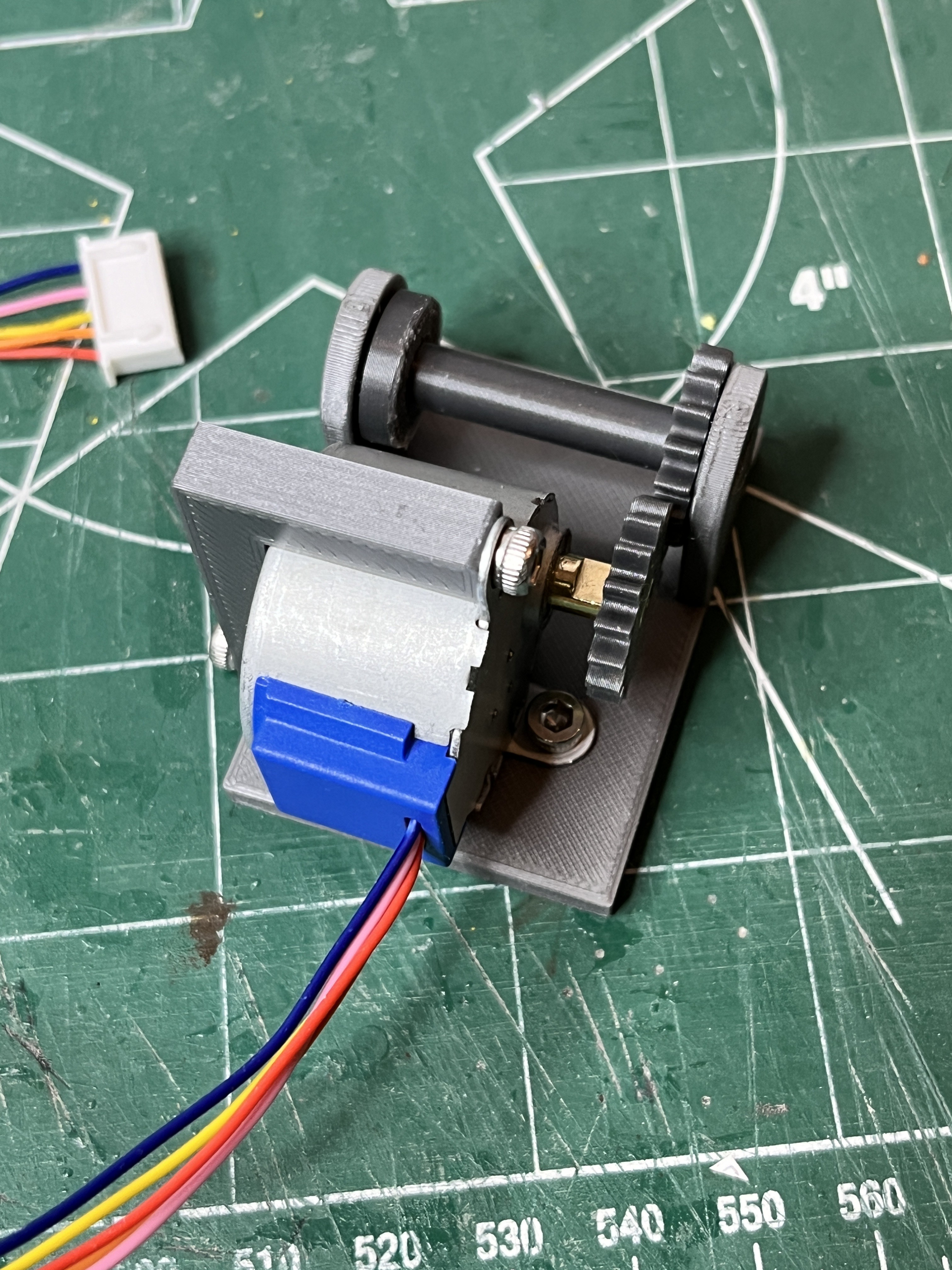
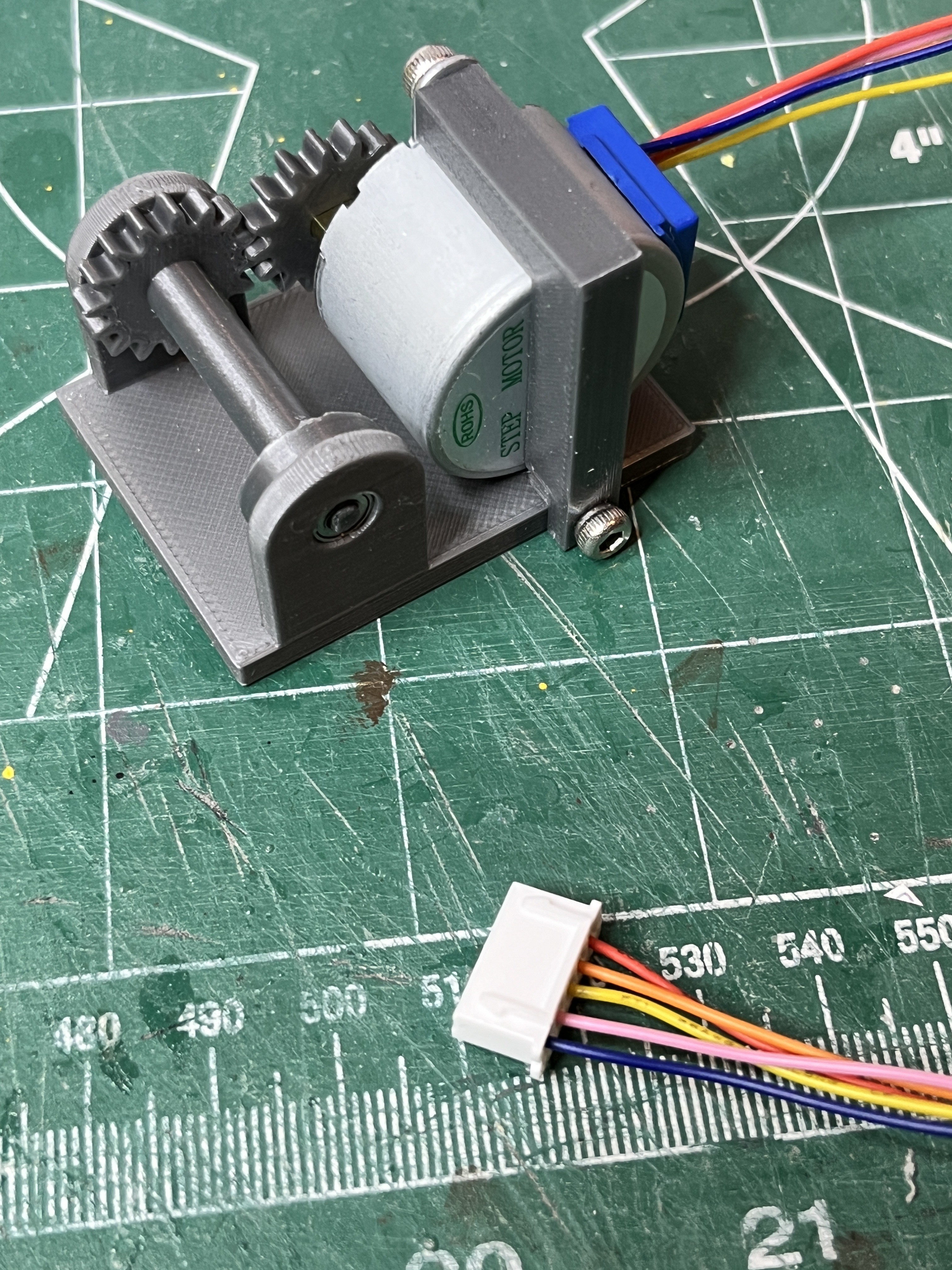
I like the new slip ring. It is smaller, can handle more amperage (larger wires) and is metal. Here the stepper motor and slip ring mounted on the new and improved motor mount.
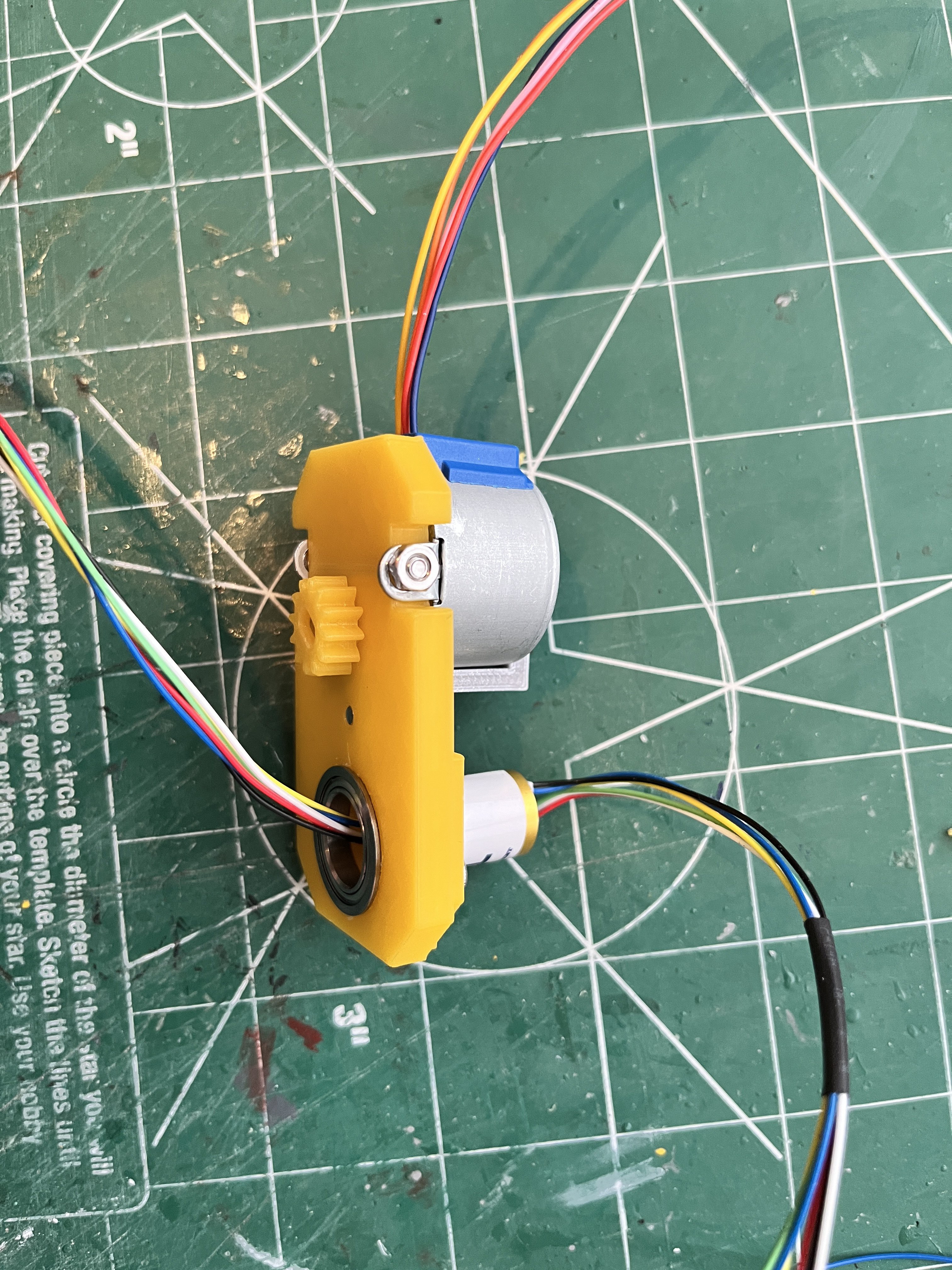
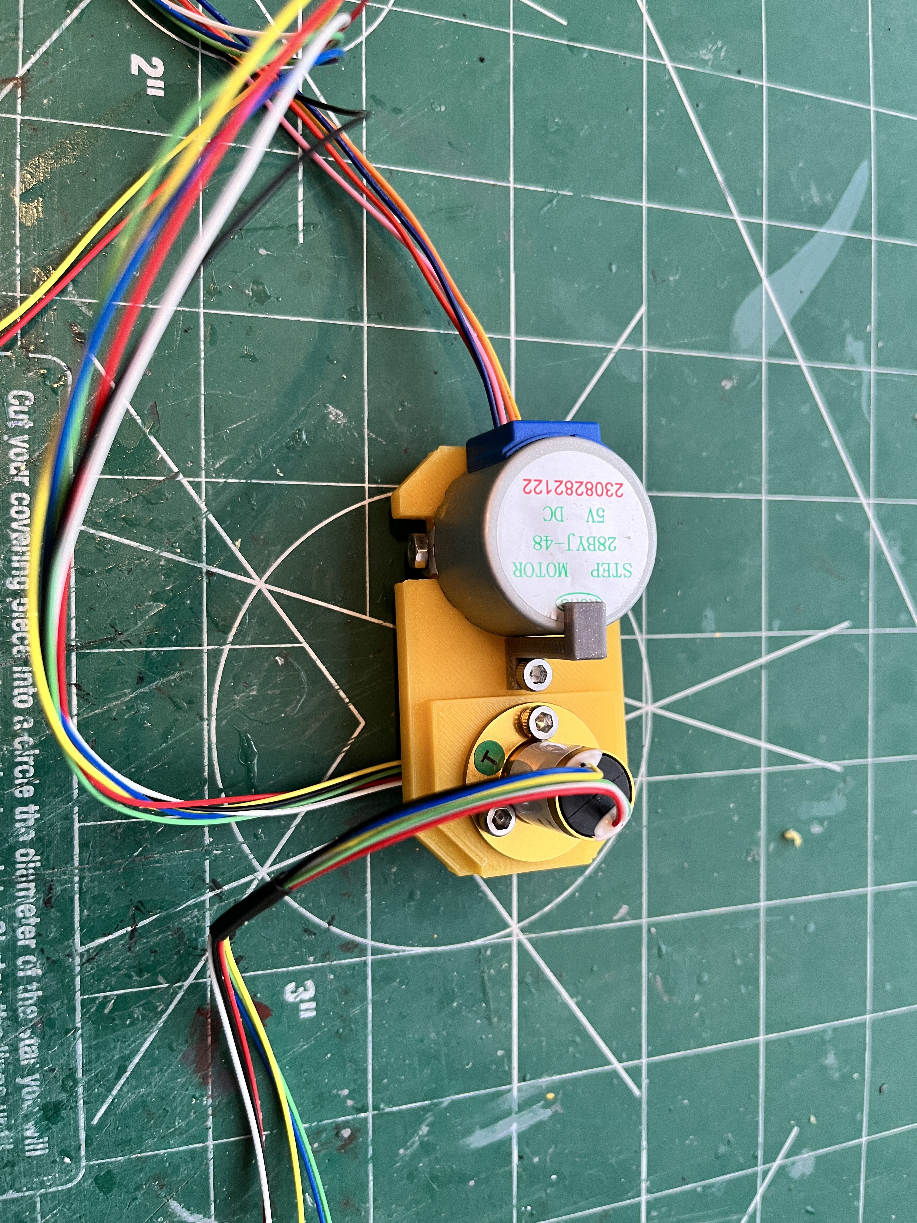
One thing I wanted to point out was that I bent over the mounting tabs on the stepper motor to make it attach.

When looking at the Turbo Squid drawings I realized the model's stairs have 3 steps and the NASA drawings/Turbo Squid show 5 steps. Something is wrong with the model. I remeasured the 25 ton side structure and it looks good. The tallest part is supposed to be 15' or 76.2mm. I then measured the end panel MH-EndA and discovered the problem. The height is incorrect. The model's height 47mm. Per the NASA drawing below the height should be 11' or 55.88mm. This means the motor housing is almost 10mm too short which produces a significant visual issue.
Here are pictures of both Turbo Squid (top) and the model (bottom). You can see the 25T-Main Cross Beam is too tall and bulky.

I still believe the main boom structure is correct. Fingers crossed.
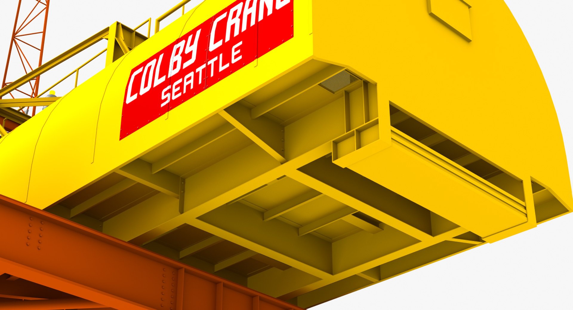
Since I'm redoing the motor housing, the most visible part of this housing when its almost 7' in the air is the underside of the rear portion that hangs out over the tower. The model does not have much detail.
Here is a picture of the Turbo Squid model of what it should look like. A lot of opportunity for detail.
Here is a sneak peak at the new crane framework. The floor is printing now. Things are going slow with only one printer. After the floor is on there are small plates at the rear and then the weights.

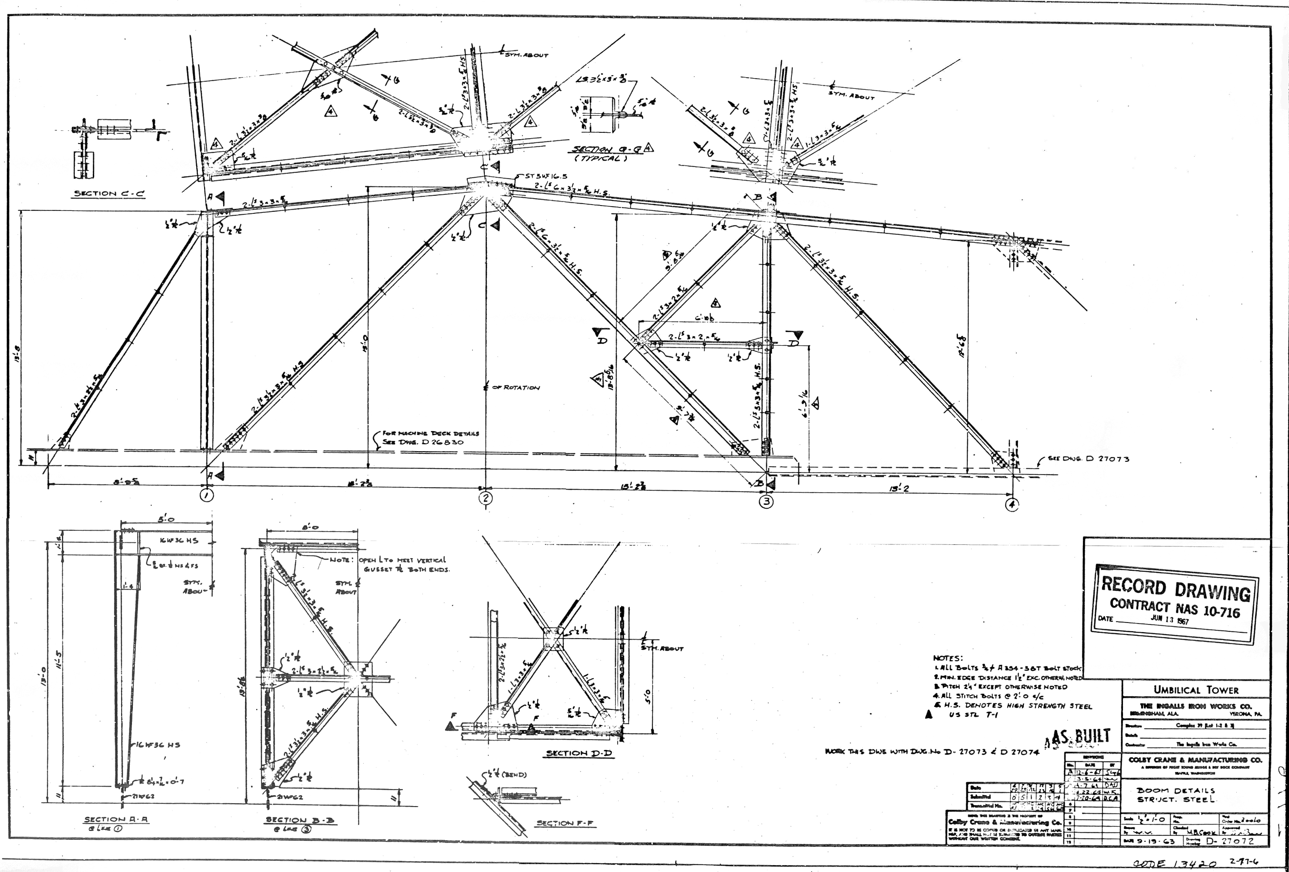
And now I discovered the ChristineZ crane motor house is 13.74mm too long and the bands (joints) around the housing are raised and they should be indented, see Section-DD.

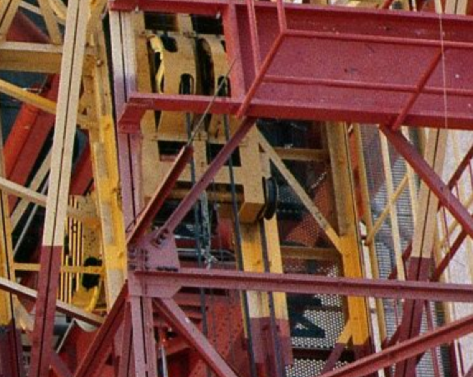
Here is GTGeo's response to this: Here's a close up photo showing the joints.
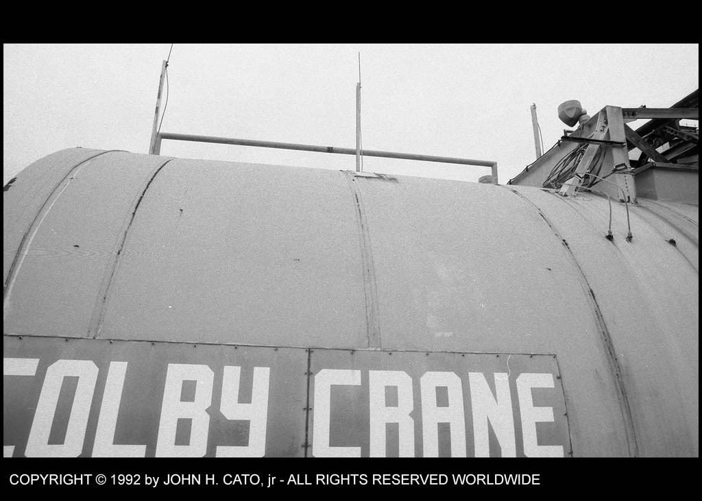
The joints are very subtle.
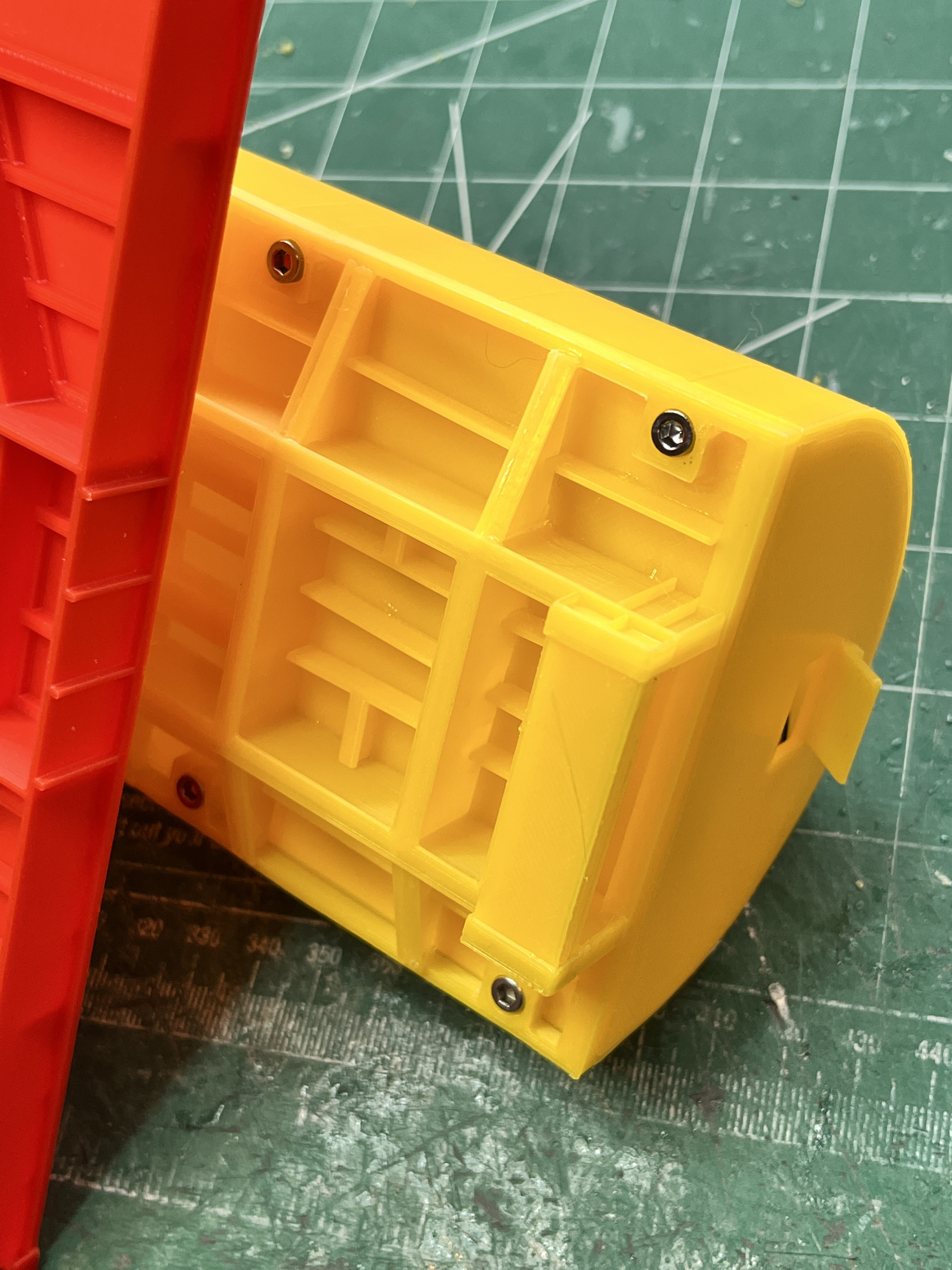
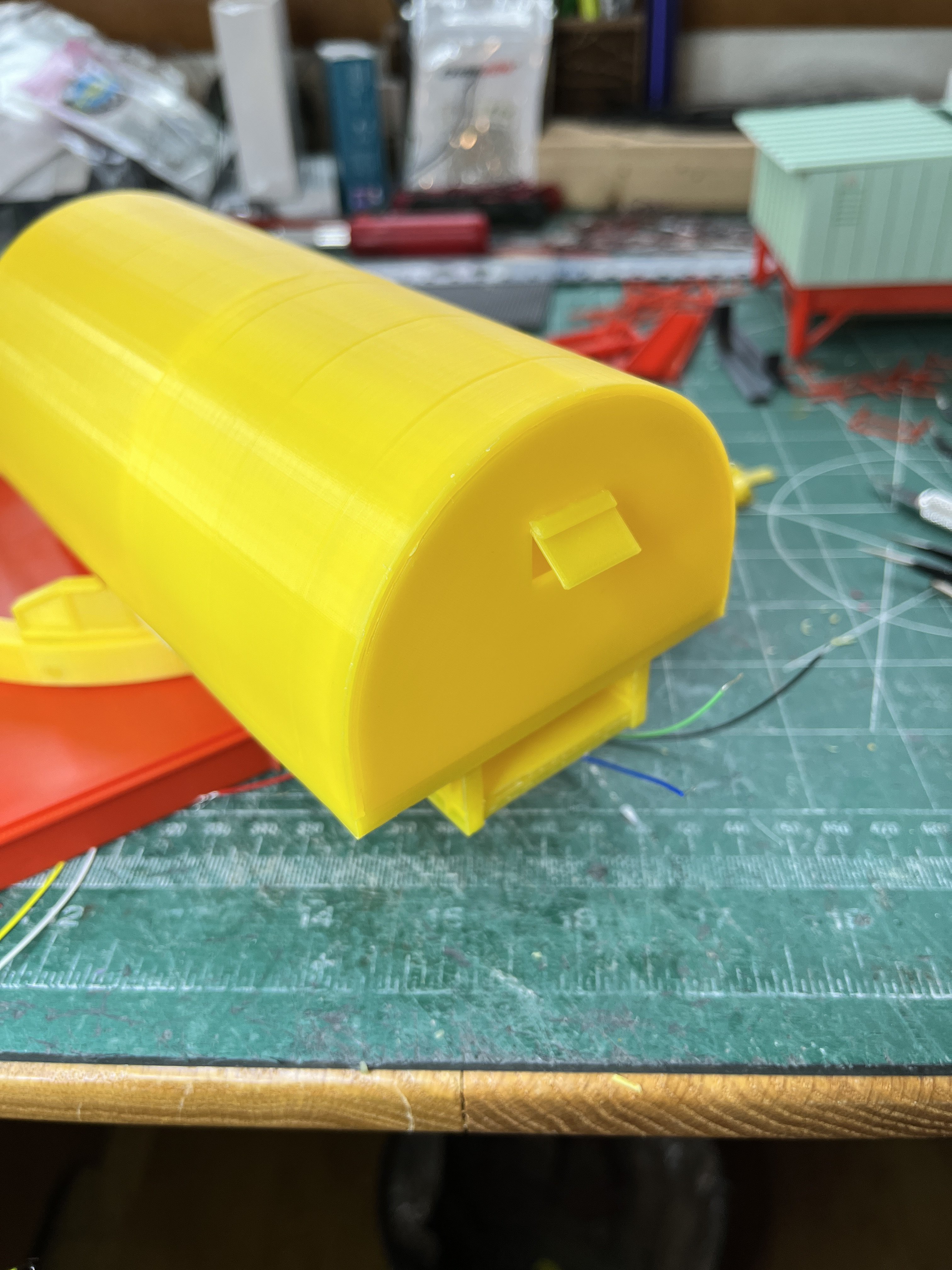
Here is the new and improved crane motor housing. They say a picture is worth a thousand words. I will simply let the pictures do the talking.

If I were a real modeler I would get out the airbrush and weather the model. Maybe I will build a second LUT but this time weather it. Wait a minute! What am I saying? That would be crazy!
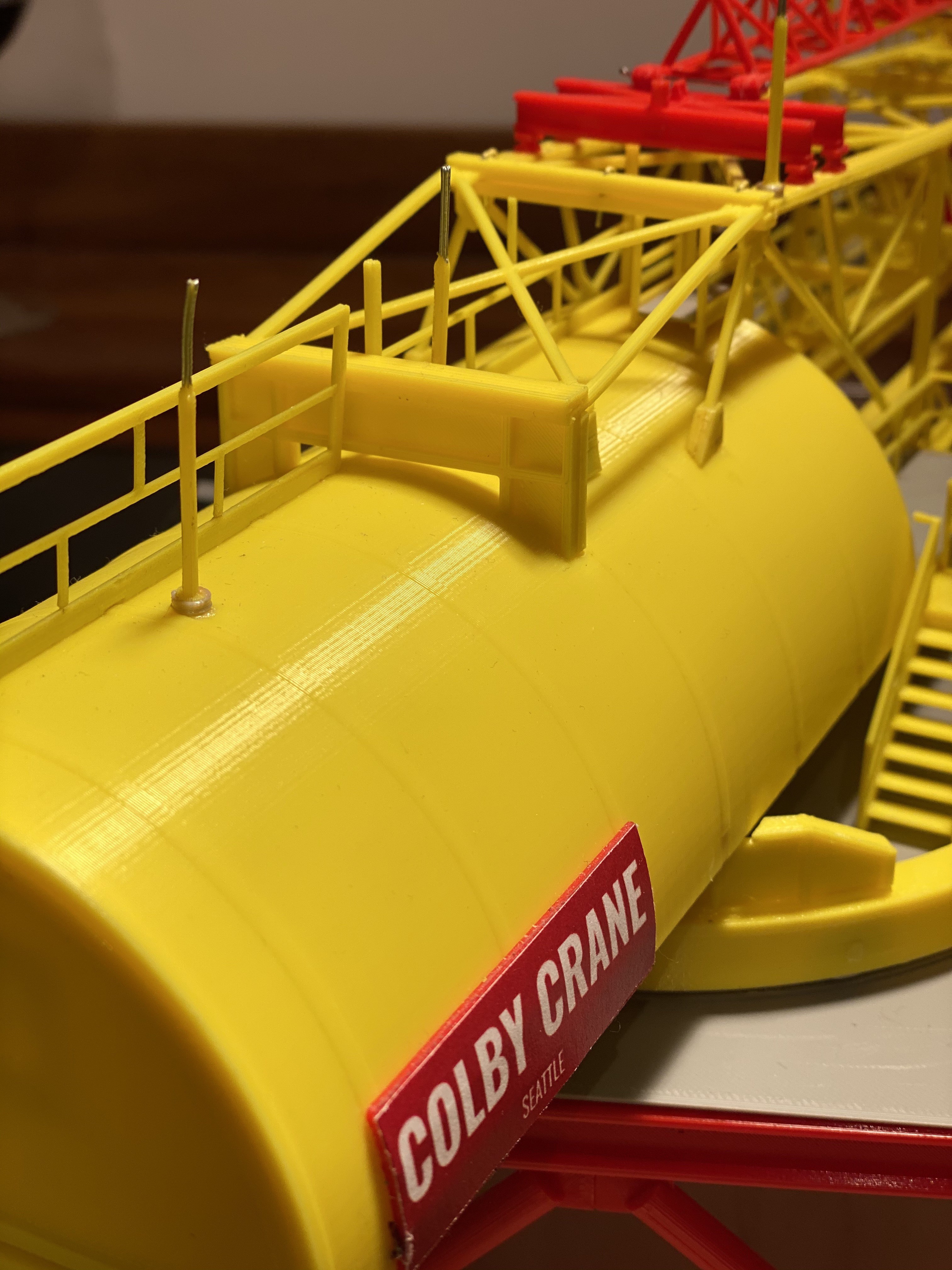
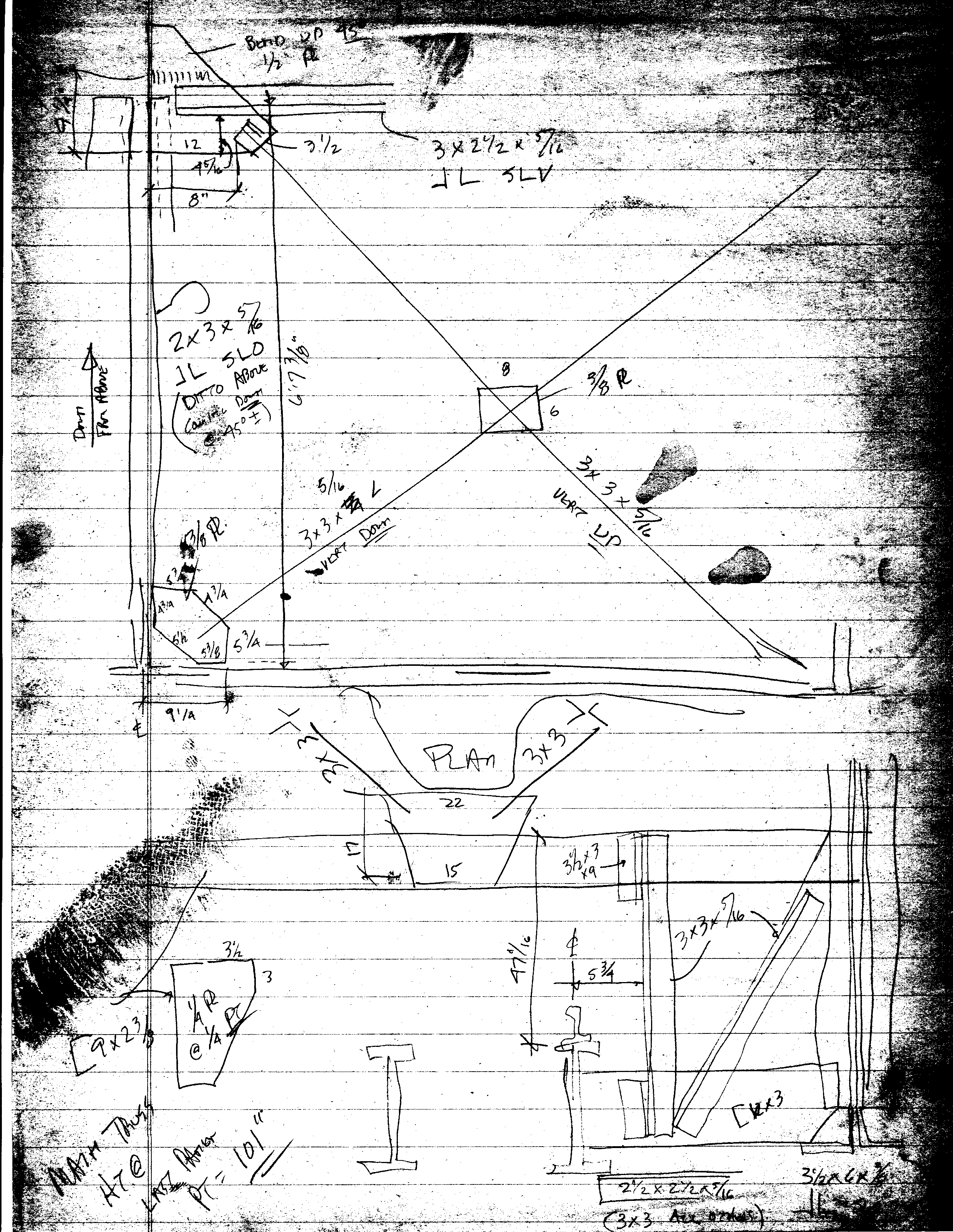
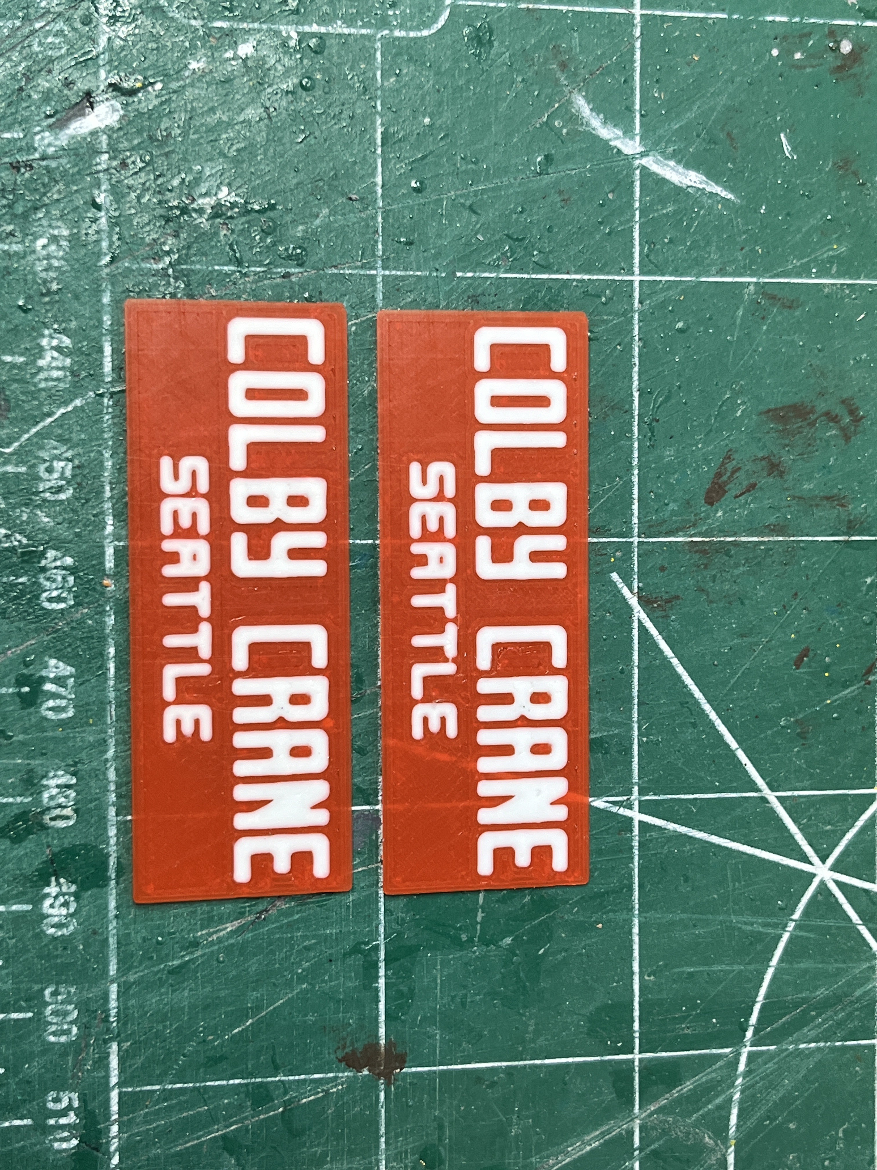
Two years ago I figured I would slowly work my up the tower and then at the end simply print the crane and be done. I'm looking at the sign. This drawing shows it as 14 gauge metal or 5/64" thick which at scale is 0.033mm. Well that's not really possible but it should be as thin as possible.

The ChristineZ crane has a thick plate with a decal on it which does not look very accurate.
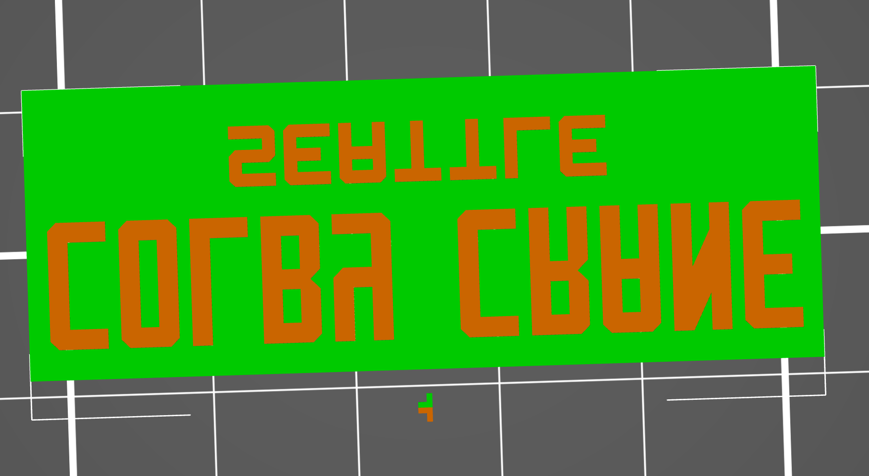
I print other people's models to learn new tricks. Here is a trick to make a thin (2 layers) sign. I first drew the sign making both a letters and background file. Notice that the bolts around the outside make good reference lines.

The trick is to print the sign upside down so the "good" side is down. Bring both parts into the slicer and overlay them exactly. Now you can remove the background, slice and save that print. Ctrl-Z and then delete the letters. Slice and save that print.
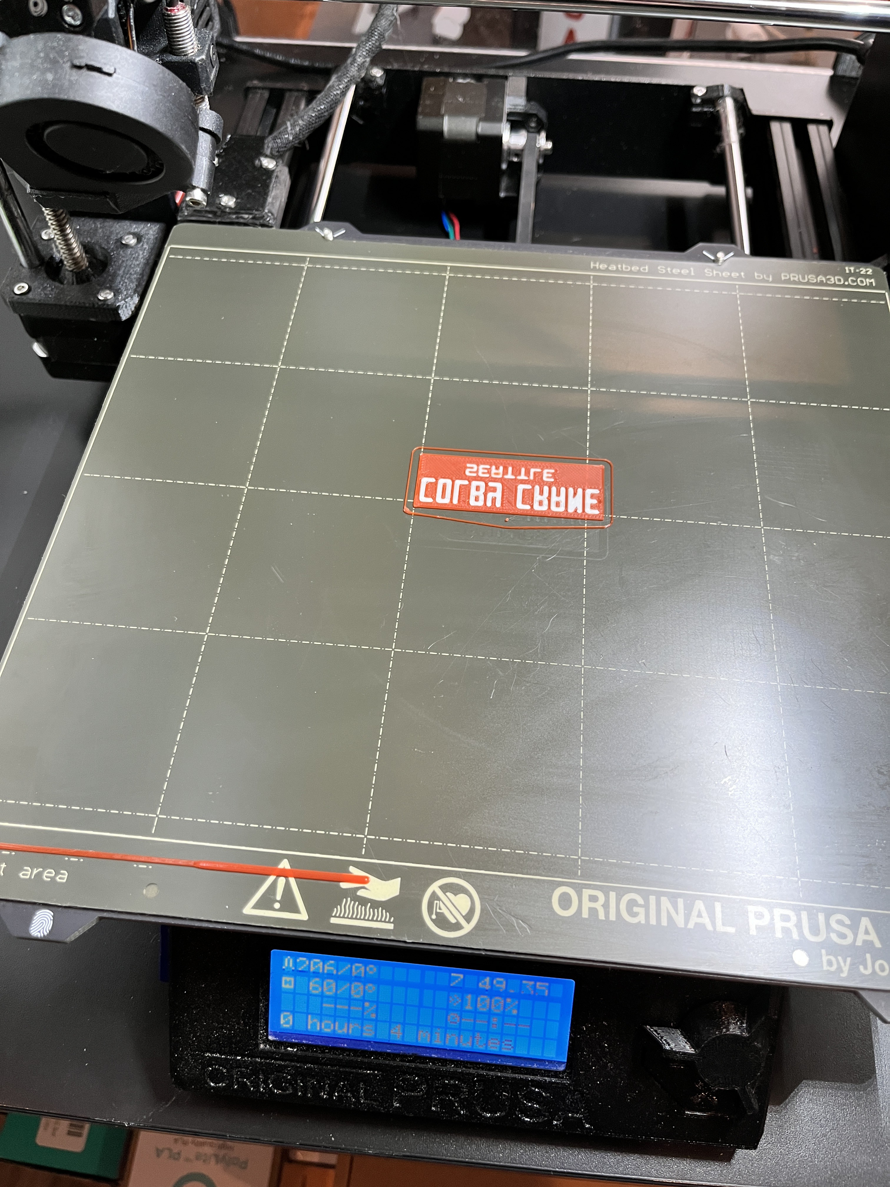
Start by printing the letters. Leave the letters in place. Now print the red background and the printer will carefully work around the white and adhere to the letters without disturbing them.
GTGeo wrote: The dent in the lower left was never fixed, compare this photo to it on display at the cape.
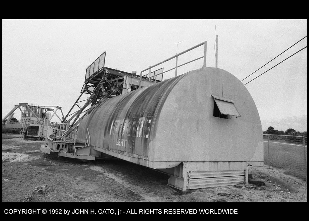
The dent in the lower left of the crane that you said was never fixed, I see that in at least two pictures. Is there some cool story behind that? I'm considering modeling it. When you model the USS Missouri most people add the dent in the hull where the kamikazi plane crashed. If there's not a cool story maybe we can make one up and turn it into urban legend.
GTGeo wrote: LOL, no cool story. My guess is the Demo/Salvage company just rammed some cribbing under it after it was removed. They didn't give a s*#t because to them it was just scrap metal.
How about an alien space craft was monitoring a launch when the roar of the engines startled them and they bumped into the crane trying to get out of the way.
Crane Motor House redesign: I will make two versions; automated and non-automated. For those that don't wish to automate the crane, the top will be one whole part that is glued onto the base just like the original model. For those that wish to automate their crane the top will be split into two parts to allow access to the electronics inside. The front half will be glued to the base and support the boom. The rear half will be removable. My first thought was to have the back slide on/off. After some though I have decided to have the back attach with screws using the knowledge obtained from building the jeep model that uses no glue, only screws.
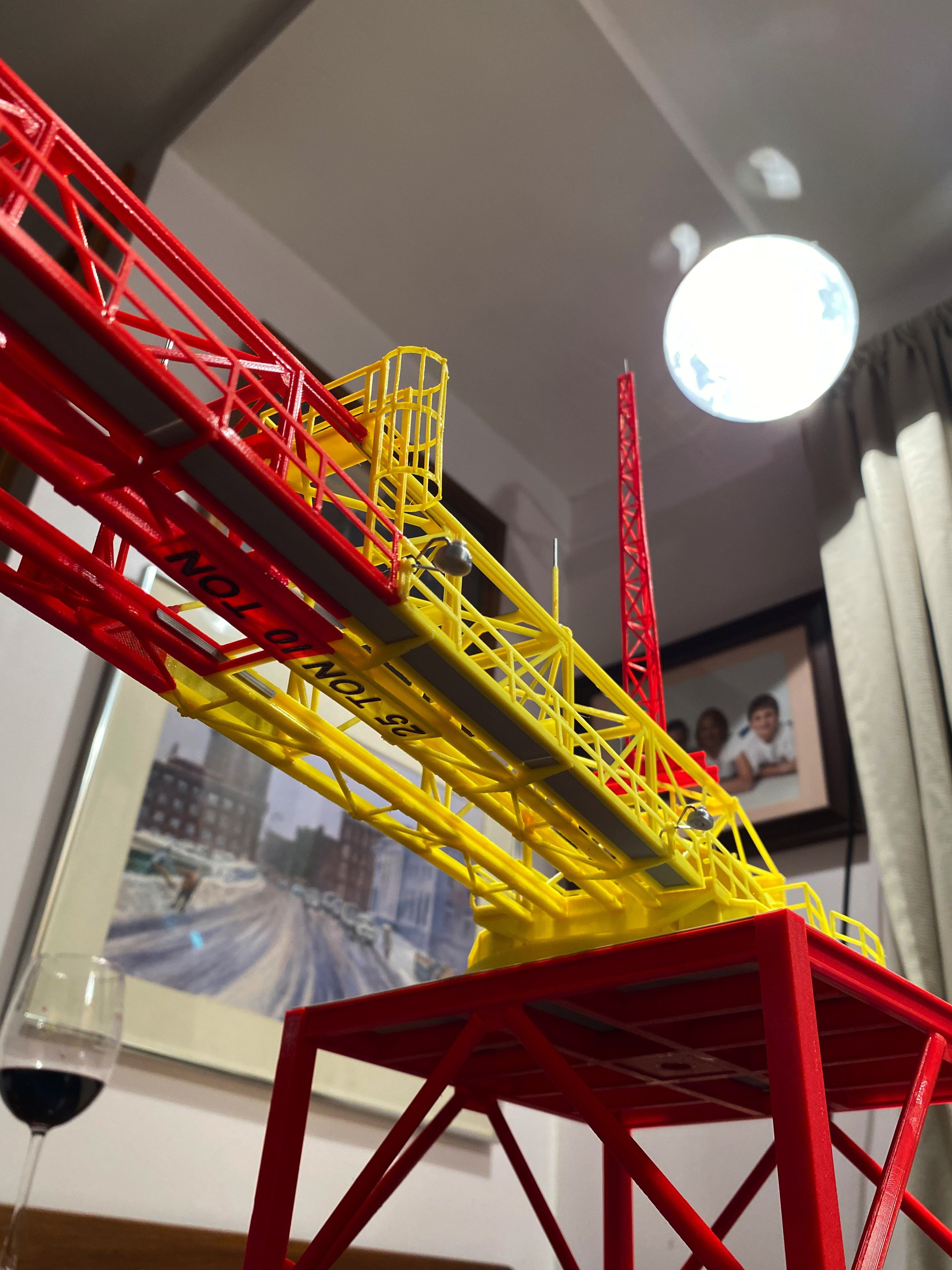
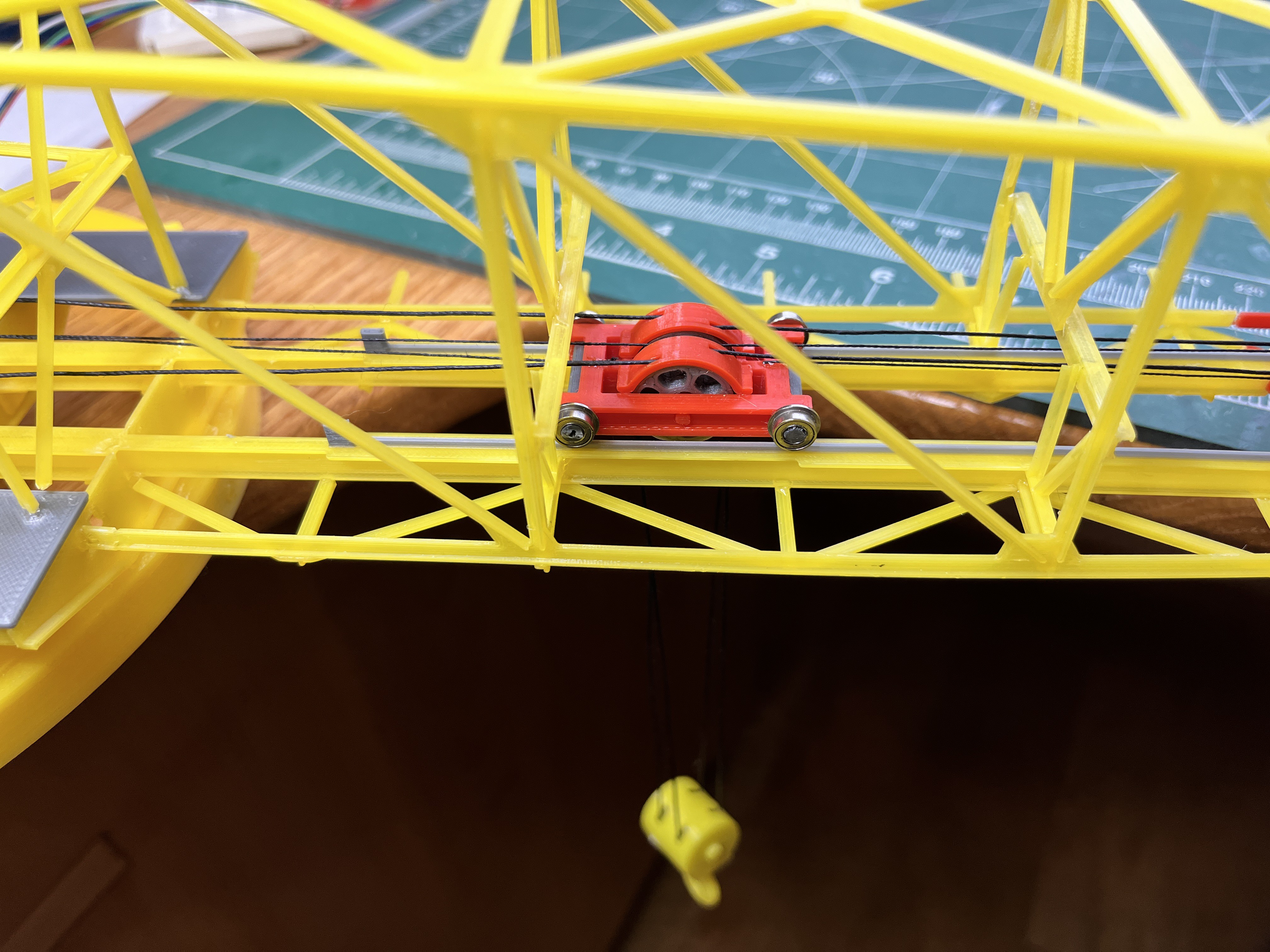
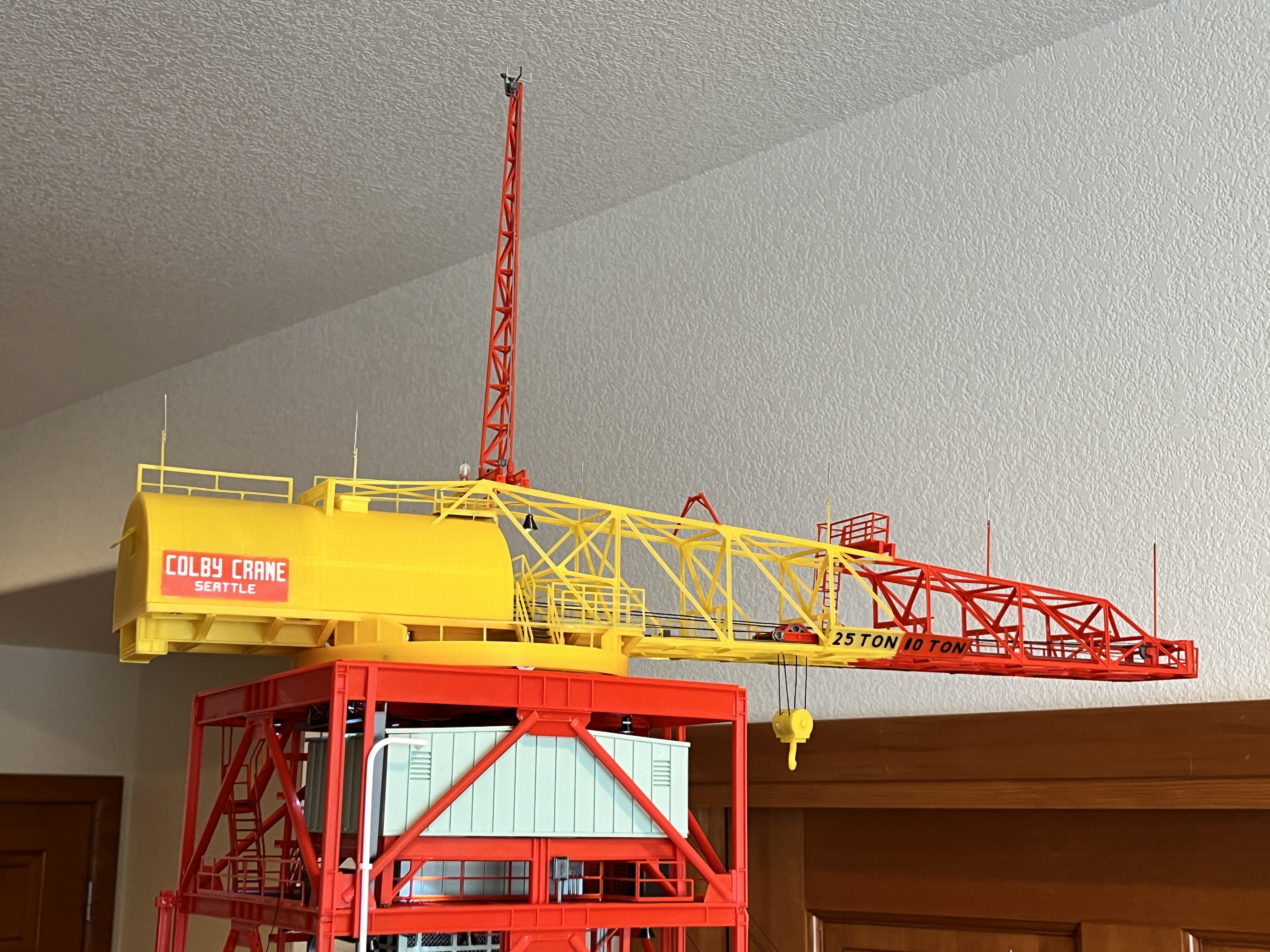
Now that SA9 is complete I am looking at the crane trolley. The trolley sits on top a pair of rails with cables hanging down between the rails. The trolley travels the length of these rails. I assume the crane model is complete given the glass of wine. Between the rails where the color transitions for red to yellow there is a cross beam that would block the trolley. I could see these cross beams as temporary construction parts to keep the rails at the correct distance that would be cut away once the structure is glued in place. On top of these I-Beams I don't see rails for the trolley to ride on.
There should definitely be a set of rails given the Cato field notes which also agrees with the MicroArtwork and the TurboSquid pictures.

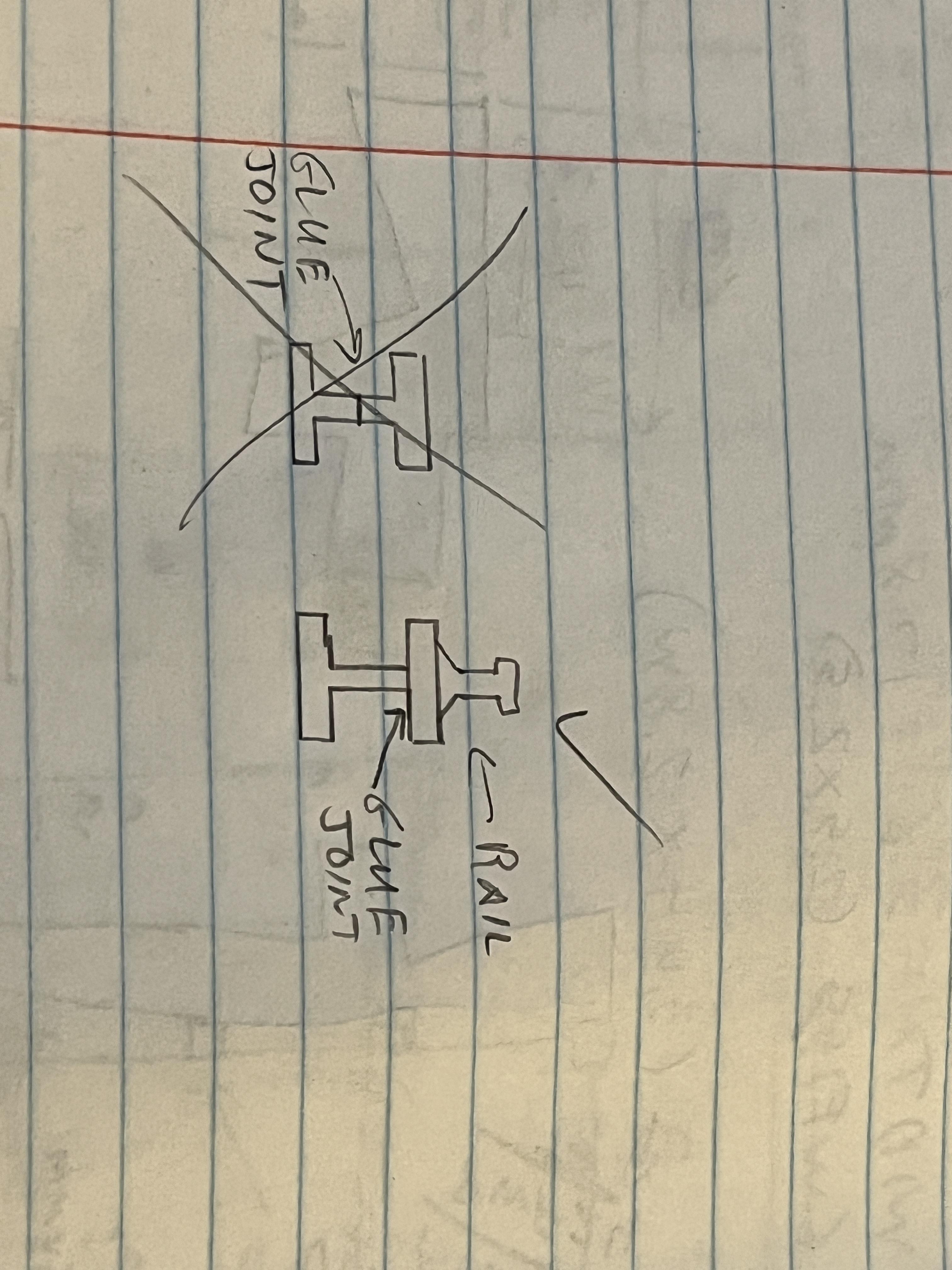
The other thing I don't like about these I-beams is that for some reason everyone wants to split them in the middle of the webbing. This leaves a very visible glue line and if your alignment is off even a little bit that will accentuate the glue line. These rails obviously need to be redesigned. I will use my standard technique of moving the glue line to where the webbing joins the flange and add an integrated rail.
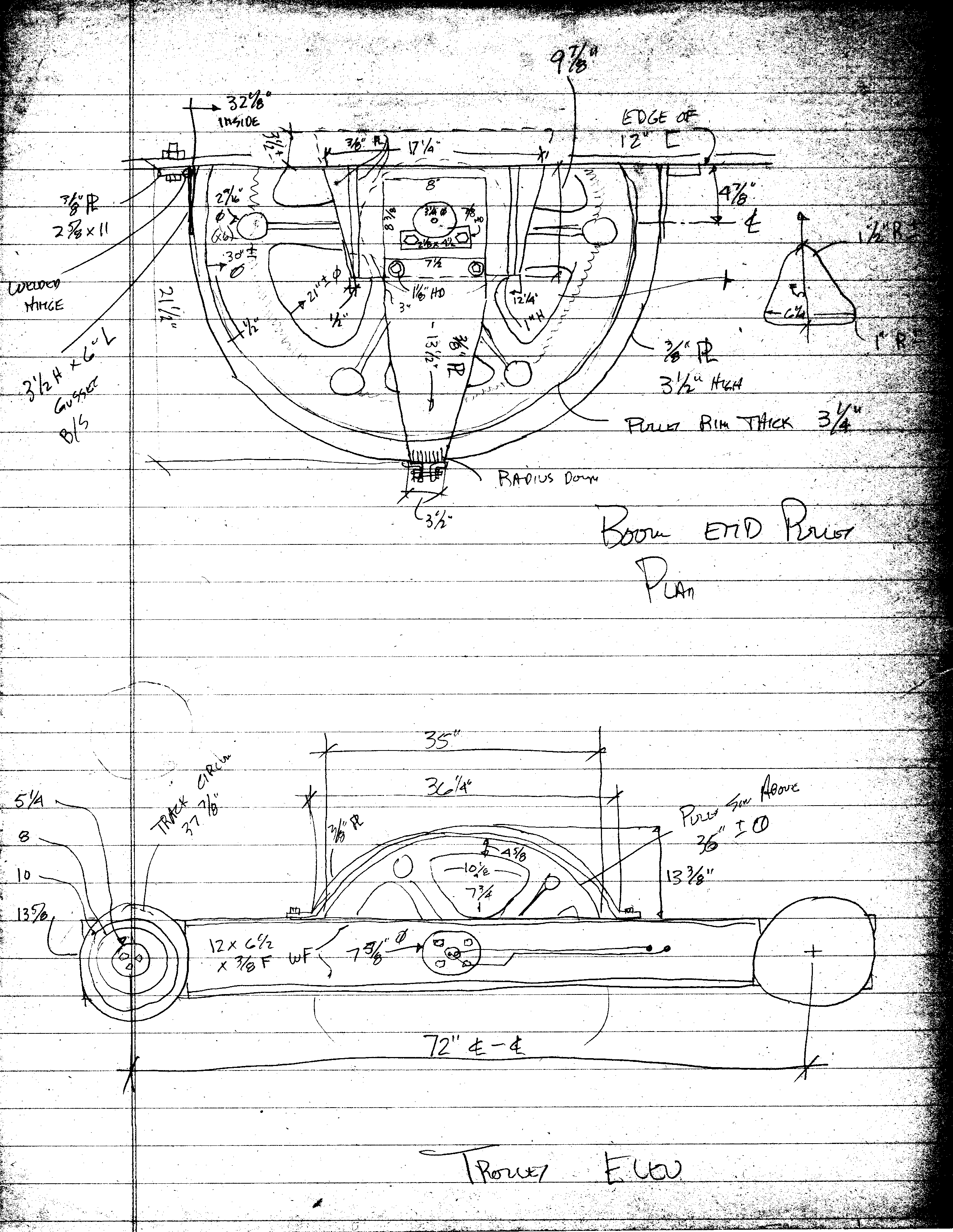
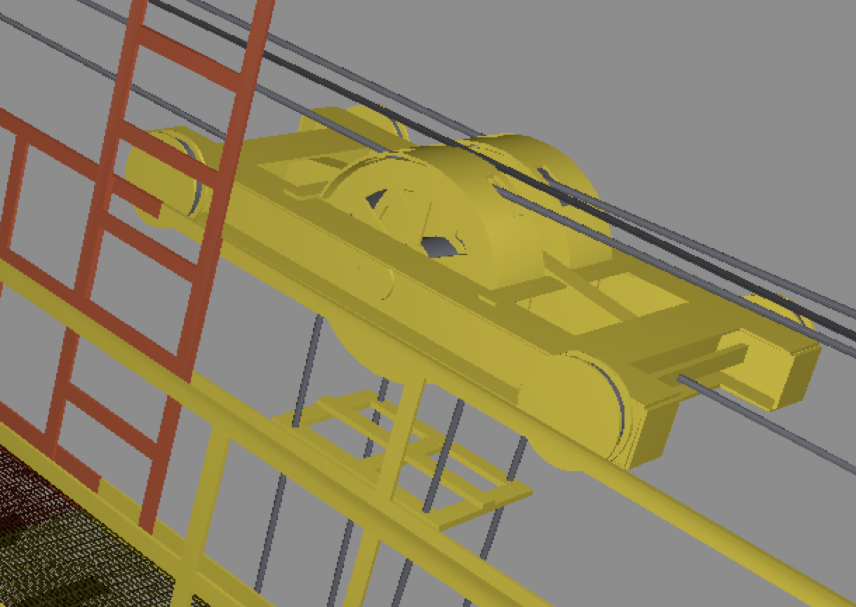
Now on to the trolley itself. There are two versions; the TurboSquid and model versus the MicroArtwork and Cato field notes. I am considering the Cato field notes the best source. The TurboSquid picture is above. The Cato field notes and MicroArtwork are below. This will take some head scratching to figure out how to get the bearings imbedded into this structure.
The other thing I looked at is the pulley that holds the hook. The MicroArtwork has it at just under 18mm diameter where the model has it at 16mm. That's close enough that I won't redesign this.
GTGeo verified this: John's field notes are the most reliable source other than a photo. Not sure how Christine installed cross bracing between the rails but I didn't. The trolly is free to move from one end to the other.

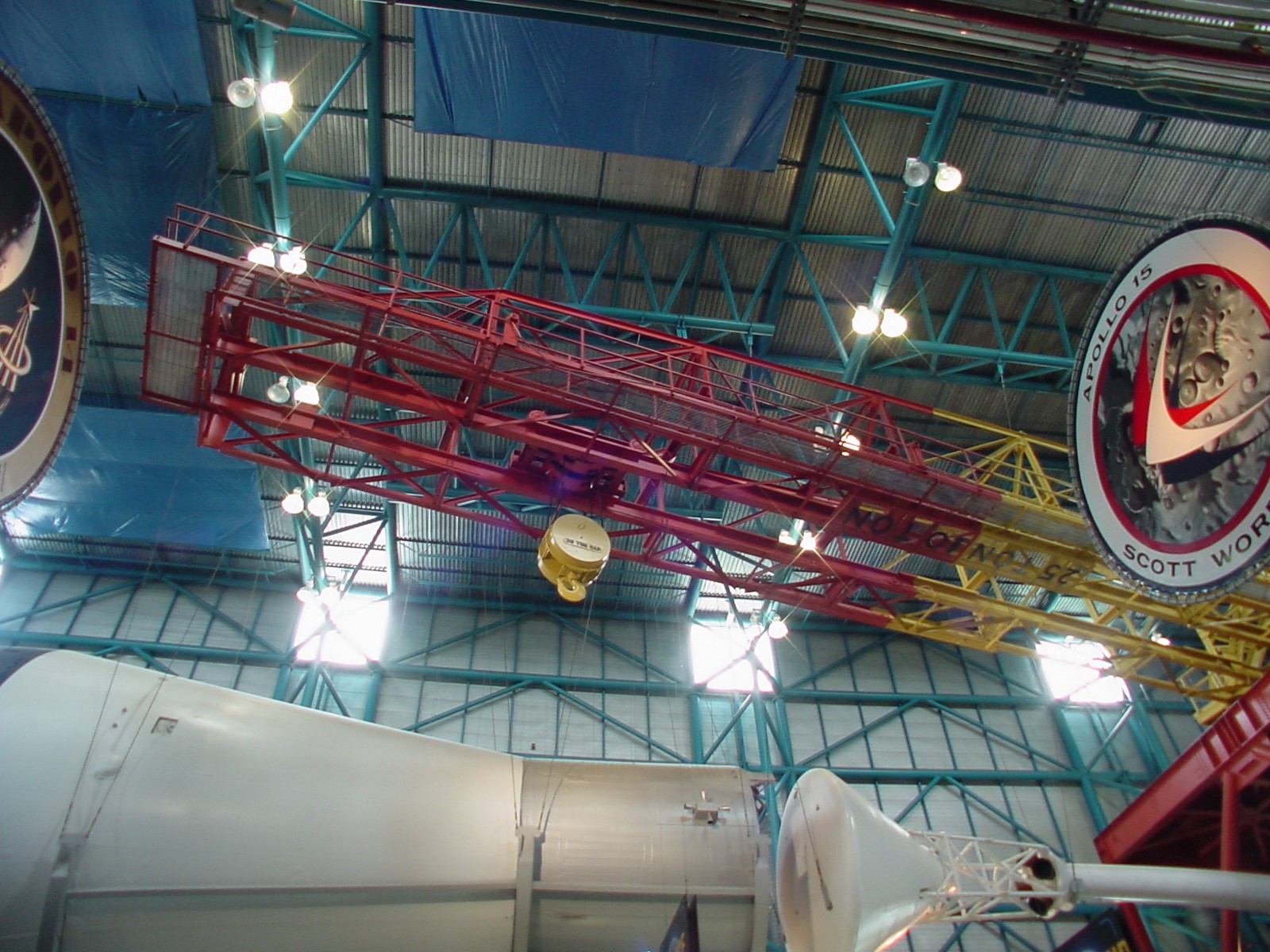
Here is a picture of the actual crane that verifies the above information. I also see that the trolley is red, not yellow.
I was able to easily source bearings that are 2.3mm wide. The field notes show that the opening for a pair of pulleys is 11 3/8" wide or 4.81mm at scale. I will use M3 washers between the pulleys and pulleys and the sides for a total of 3 bearings at 0.3mm thick. This gives an opening width of 2 x 2.3 + 3 x 0.3 = 5.5mm which is close enough to 4.81mm. Here is the trolley frame, pulleys and pulley covers. Notice that the bearing has a flange so there is an inset into the pulley for the flange. These will face each other so as not to be visible. I plan to print the pulleys as steel so they blend in with the bearing color and give some dimension to the trolley. I also sources some bearings for the wheels. The field notes show these at 13 5/8" diameter or 5.8mm at scale. I plan to use 6mm bearings at 3mm wide.
I'm going to have to redesign the hammerhead end the crane. The sheaves on the model are not correct. For some reason they are not even on the finished model. Again, the Micro Artwork agrees with the Cato field notes as far as sheave placement and for some unknown reason the model's hammerhead structure does not include the gussets as it does for the rest of the structure.
I have updated the rails for the trolley. The existing model's I-beams that support the rails are only 0.8mm too narrow which is close enough. Since I made the trolley using the exact dimensions I placed the rails on top of the existing I-beams so I don't have to redesign most of the crane structure. As a result the rails are not exactly centered, they are off center by 0.4mm which again is close enough.
OK, so I was holding out hope the crane would be accurate. It is not. The I-beams that support the rails are 6 13/16" x 13 13/16" which is 2.884 mm x 4.4715 mm. The model has them at 5.4 mm x 6.0 mm. Add to that there are no rail I-beam stiffeners along the sides. I guess I will be redesigning most of the crane although I was hoping not to.
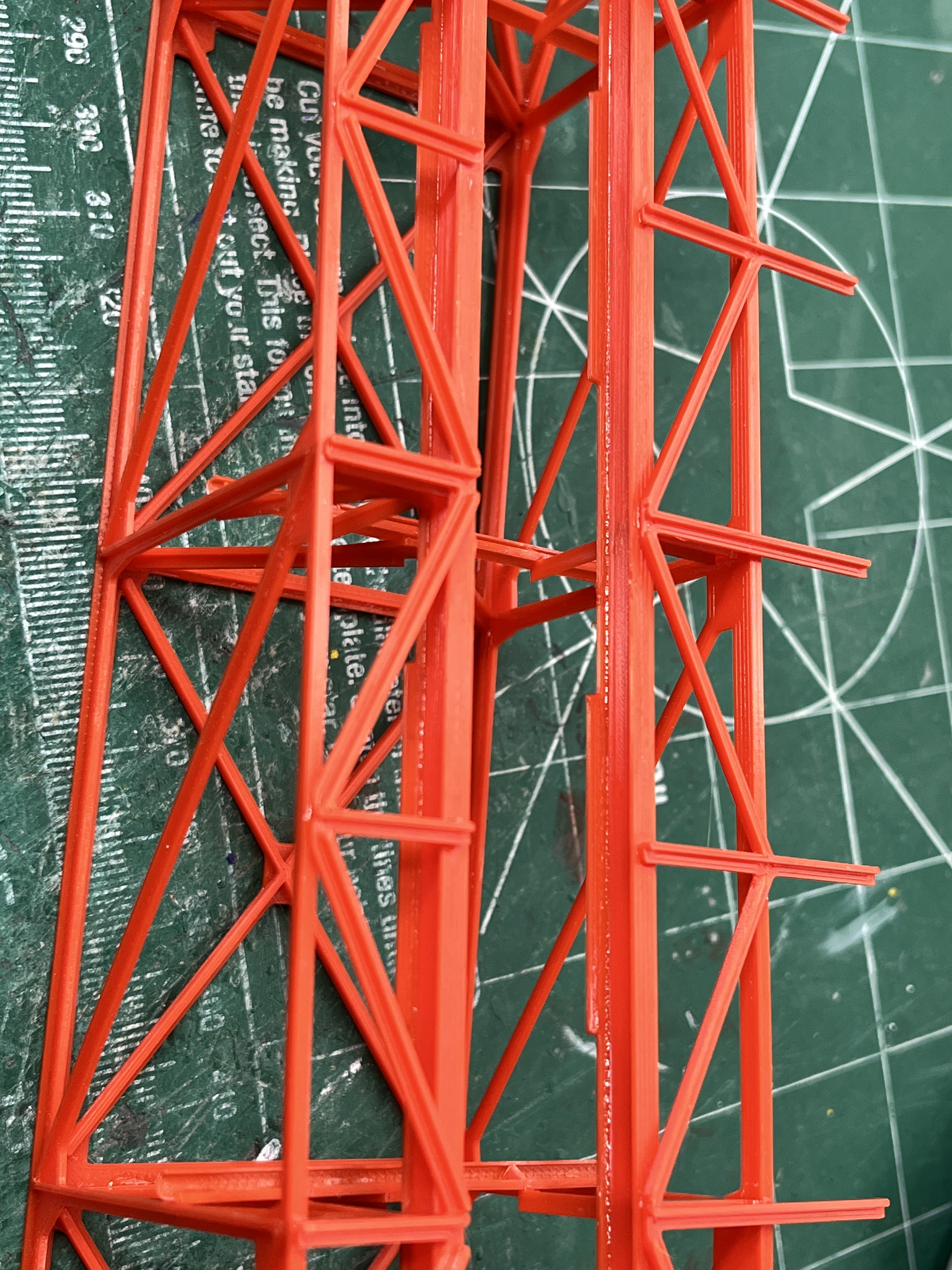
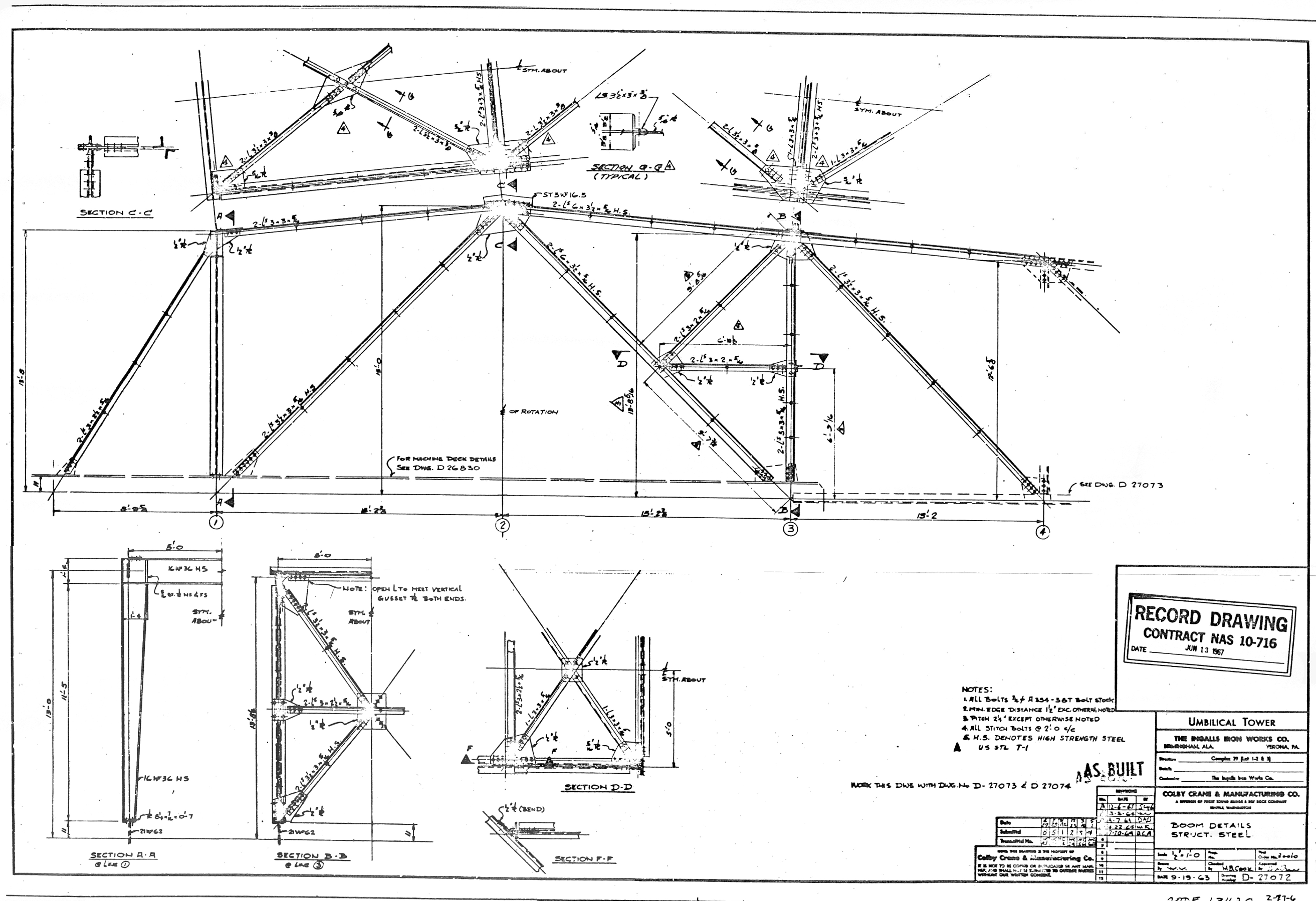
Unfortunately the more I look at the existing model the more I see wrong. Not only is the trolley incorrect along with the rails it rides on, but the steel boom structure is incorrect. If you look at the structural steel drawing side view you can see that the top and bottom beams are wider (~3mm at scale) than the horizontal and diagonal beams (~2mm at scale0. The model has the horizontal beams wider with the top and diagonal beams narrower.

In general the overall measurements are correct except where the trolley rails are concerned but given the obvious structural steel error I am going to redesign these parts.
Between cross section 2 and 3 there is a mid level horizontal structure called out in section D-D. You can see that it is a square with cross beams. You can also clearly see it in the Microartwork. Yes, it is missing in the model. The inaccuracies are piling up so I feel compelled to redesign a more accurate crane.
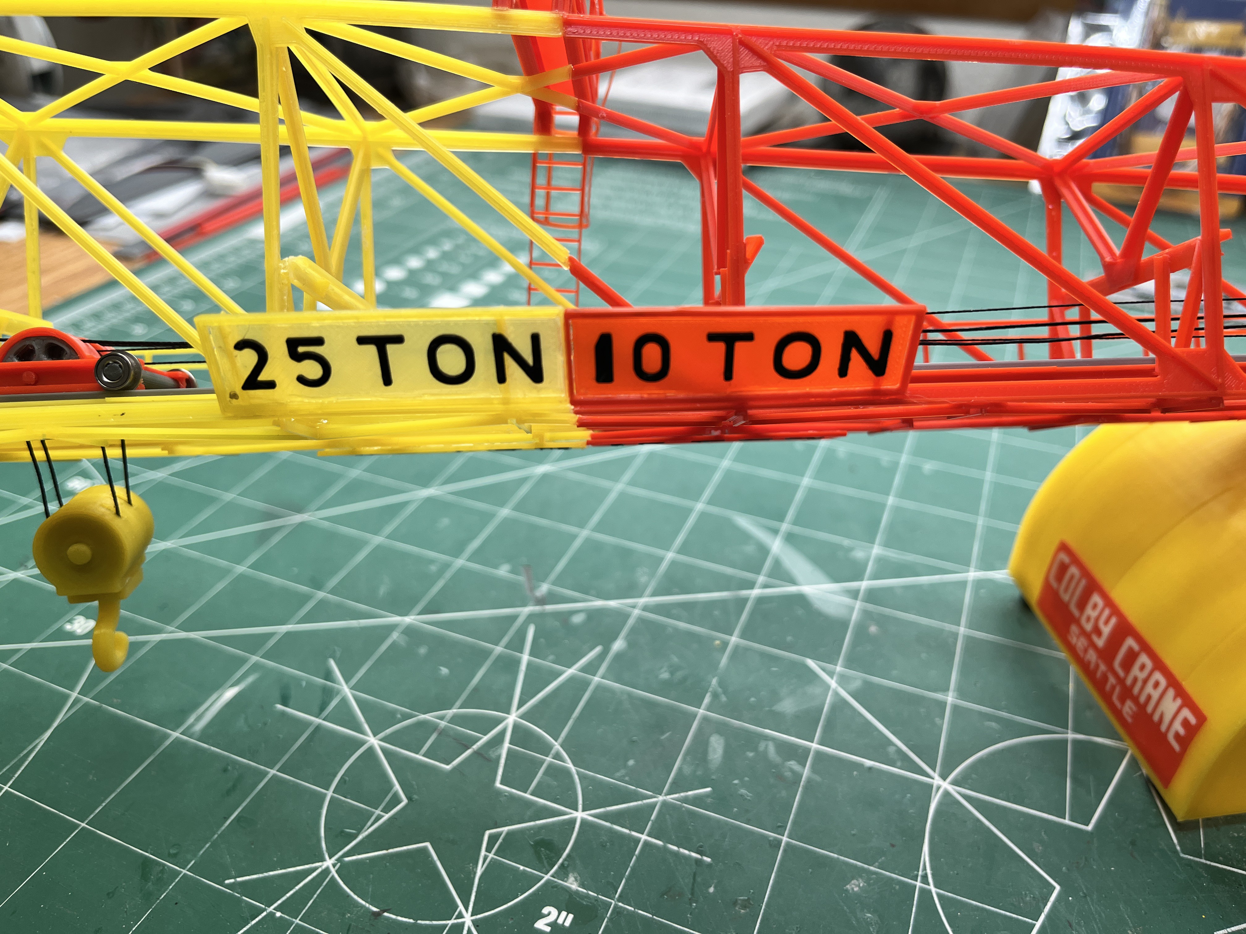
Another inaccuracy to fix. The weight limit sign on the model is not at an angle. I assume it is angled so you can read it 400' in the air from the ground. Here is the angled sign on the Microartwork and in the museum. And fortunately the exact dimensions are given by the Cato drawings.

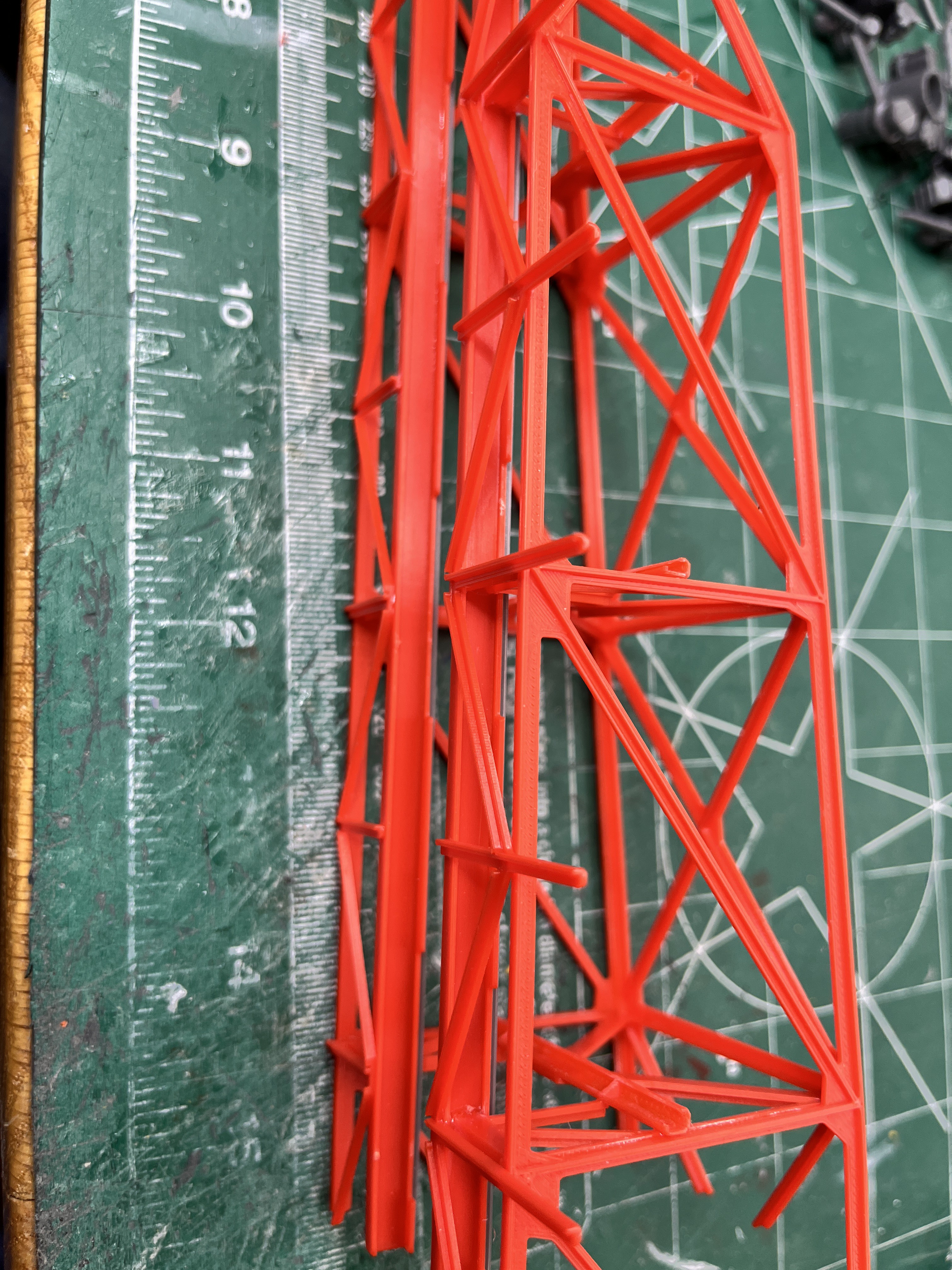
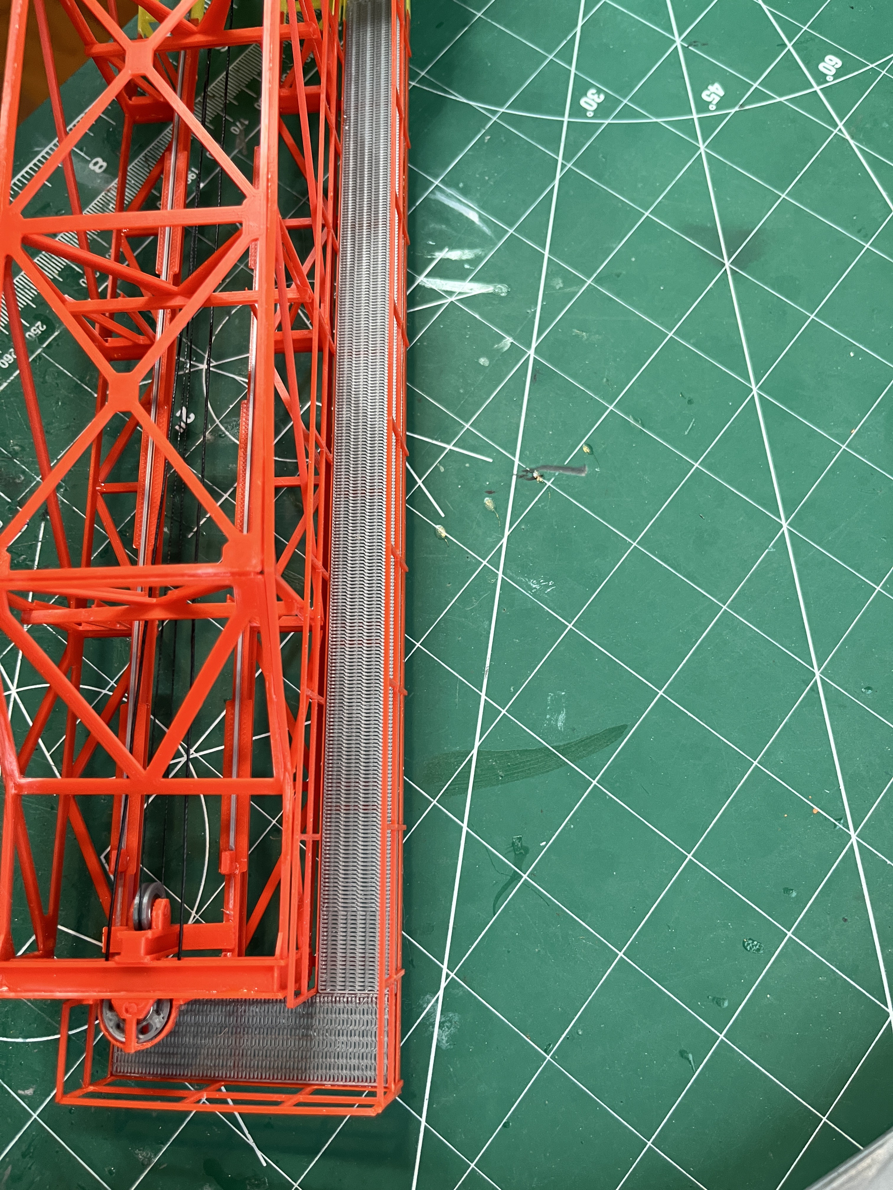
The 10 ton end is coming together nicely. The way in which the beams are oriented make it perfect to look at from the underside. Notice that the rails have temporary 1x1mm cross supports that are cut away once the structure is glued up so that the rails are held in the correct orientation. You can also see that there are brackets welded to the top of the rail I-Beam. The rail I-beam is composed of two parts, the top and the bottom. When I printed the top I performed a color change so the rails themselves are steel colored instead of red.

There is a cross beam that is composed of two parts. This is a bit tricky to glue.

The end of the crane has two little angled brackets that are glued to the inside of the end.
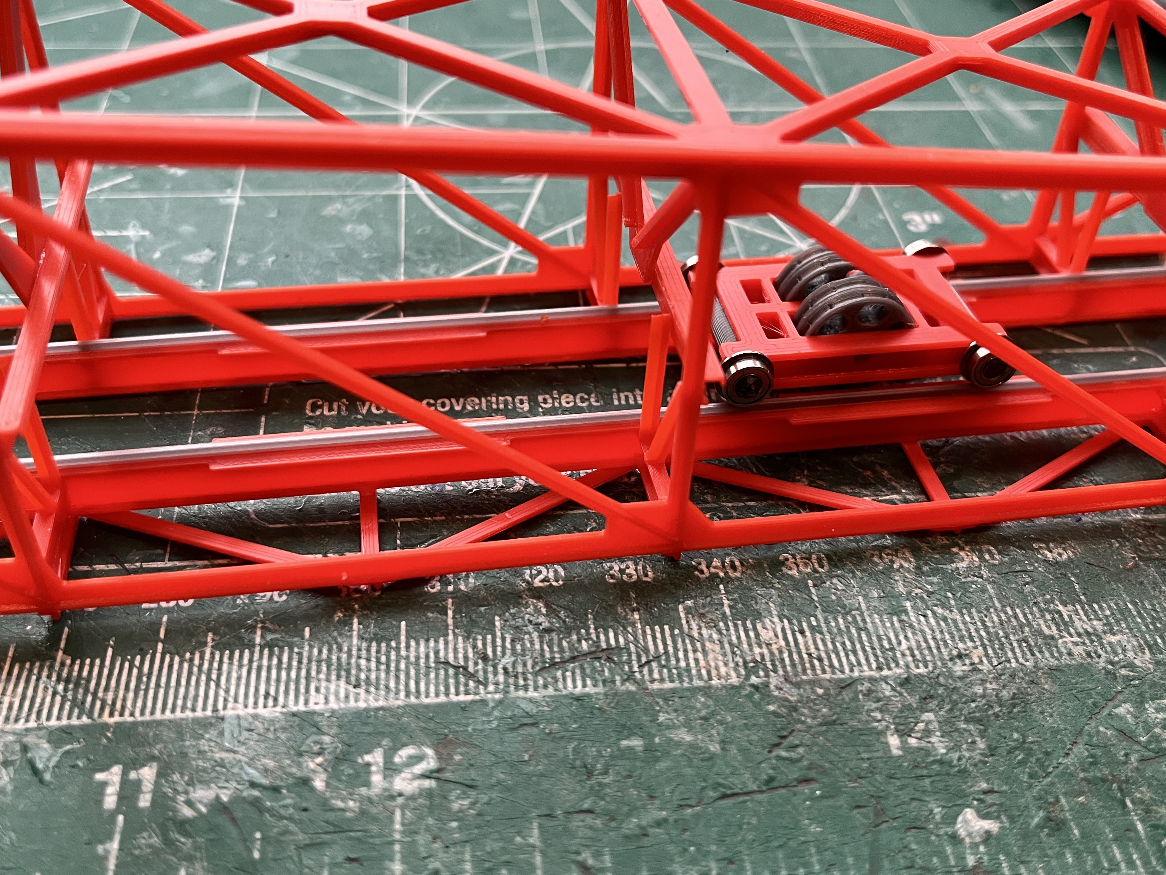
So here is the 10 Ton section glued up with the temporary cross supports removed and the trolley in place. It slides really smoothly along the rails with bearings for wheels.
The end pulleys are made and glued into place. I forgot the stops at this end so instead of reprinting all the parts I cut off the ends of the rails and glued on the square blocks. The parts to be published have been updated.
Here is the hoist winch. Notice that the lower tab is bent over. This will be glued to the floor inside the machinery house. Both automated features use these small stepper motors.
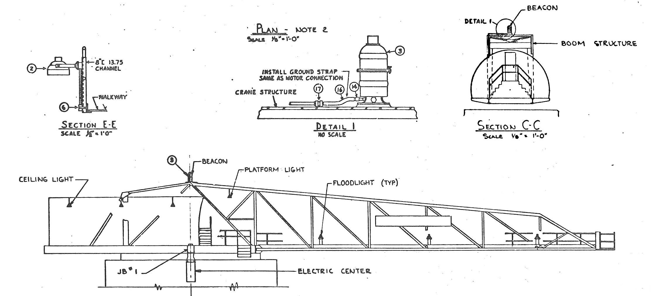
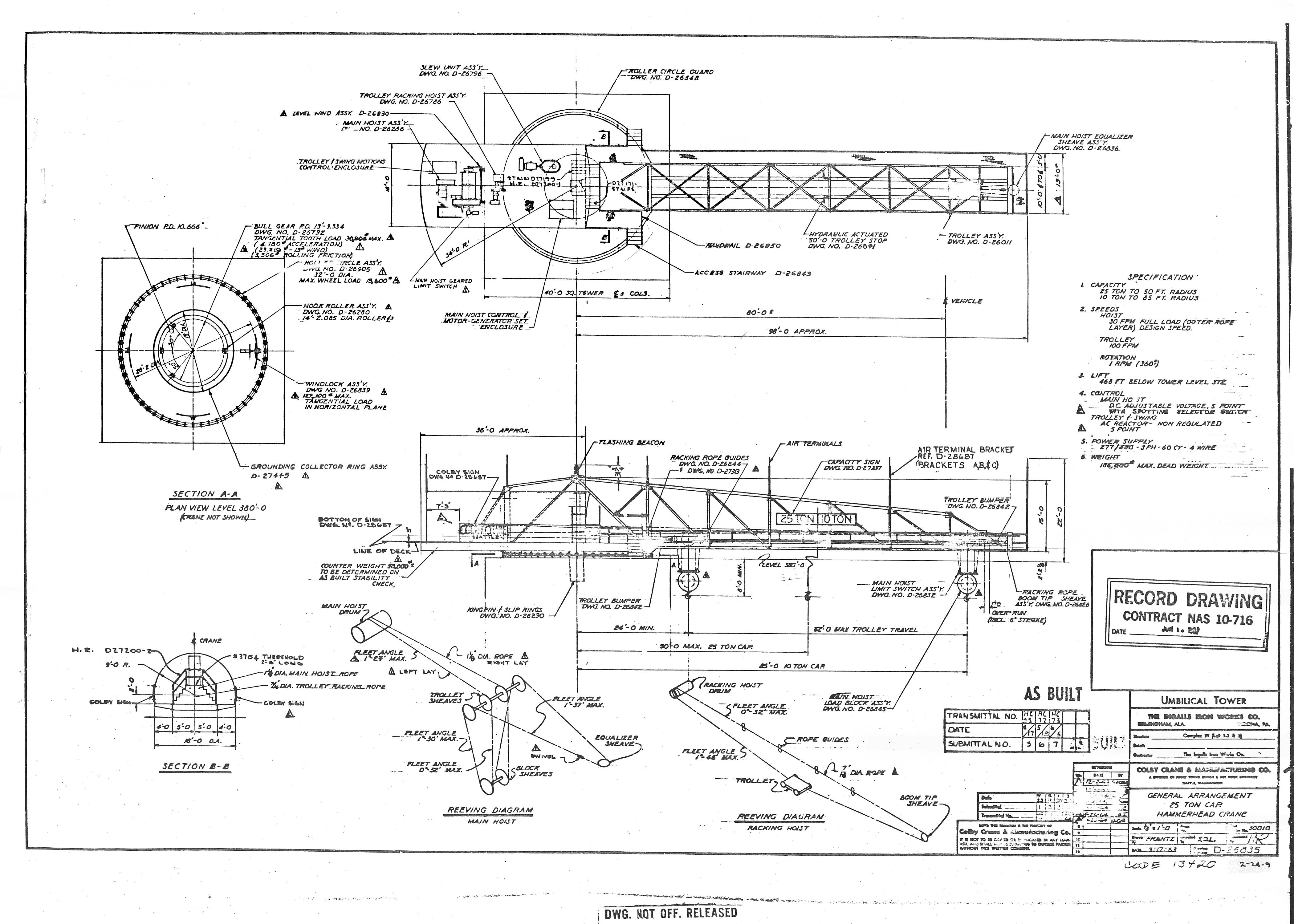
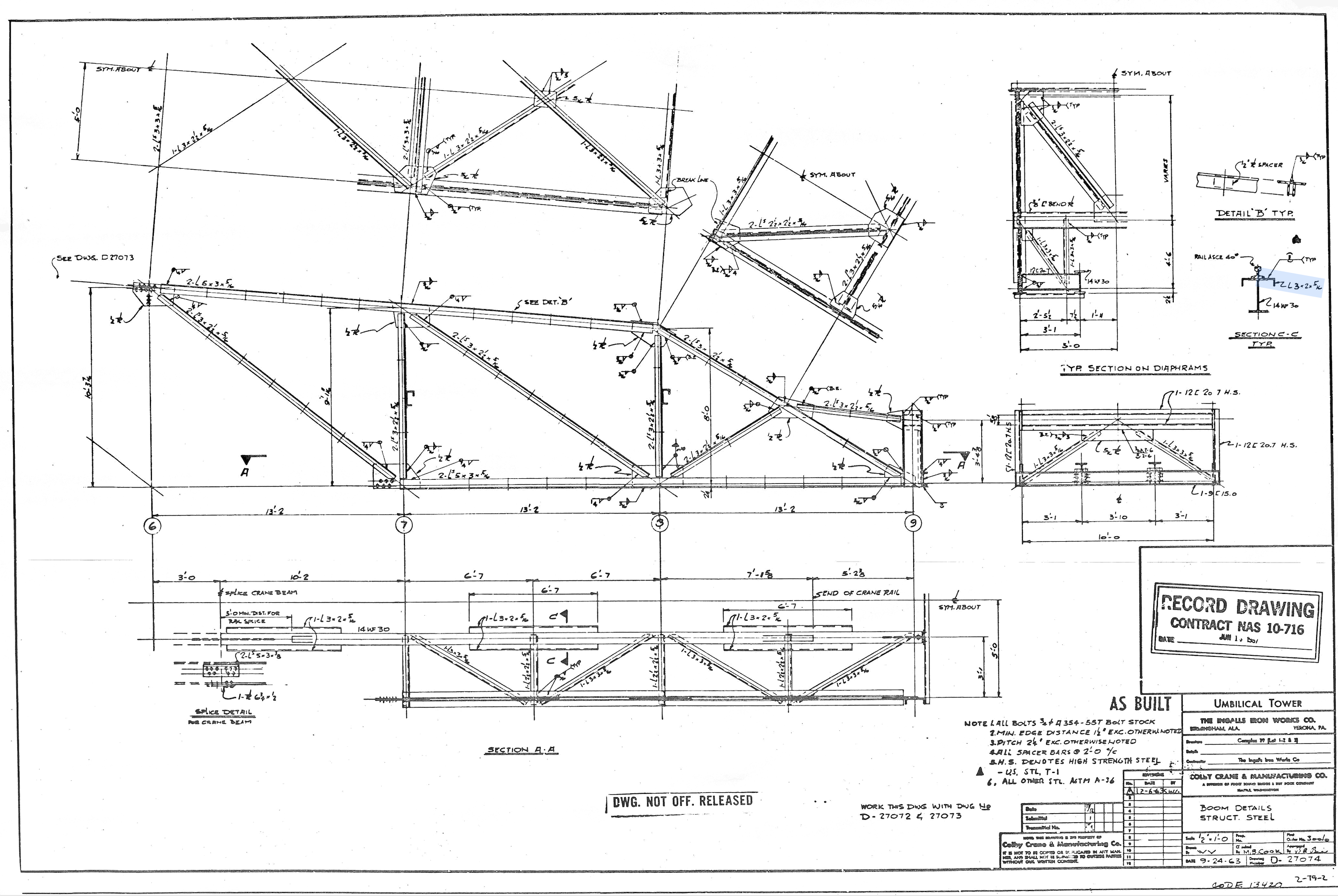
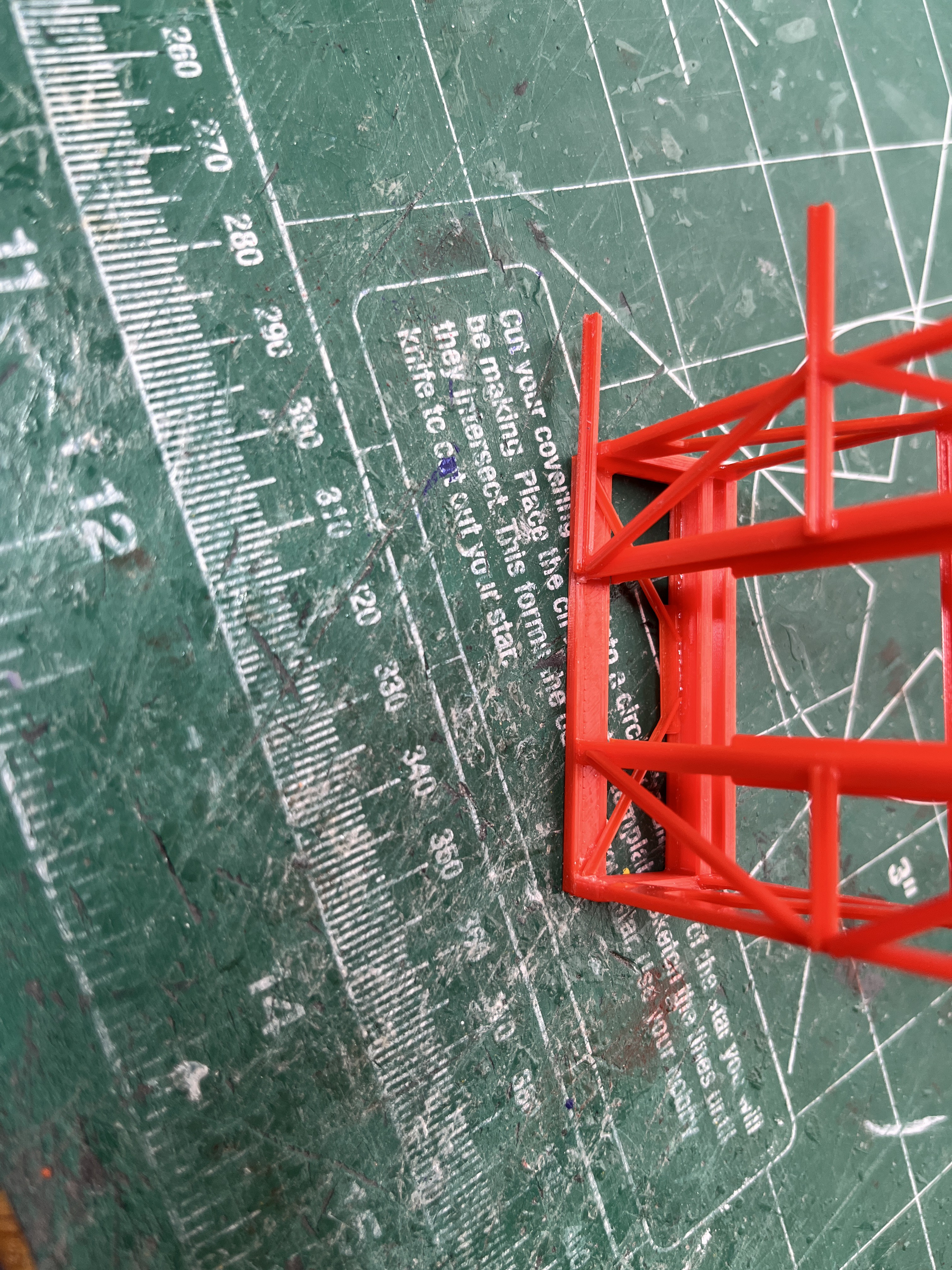
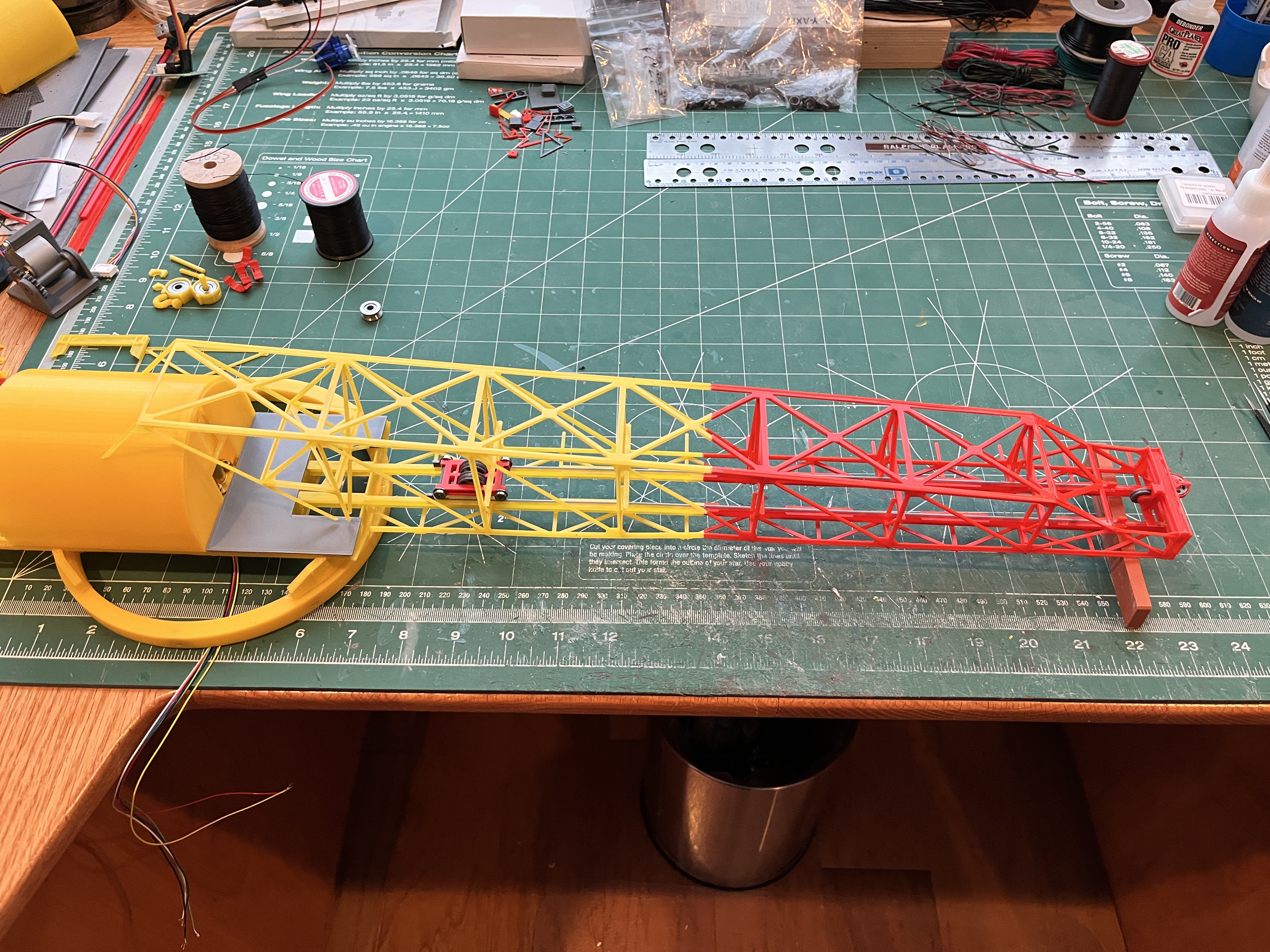
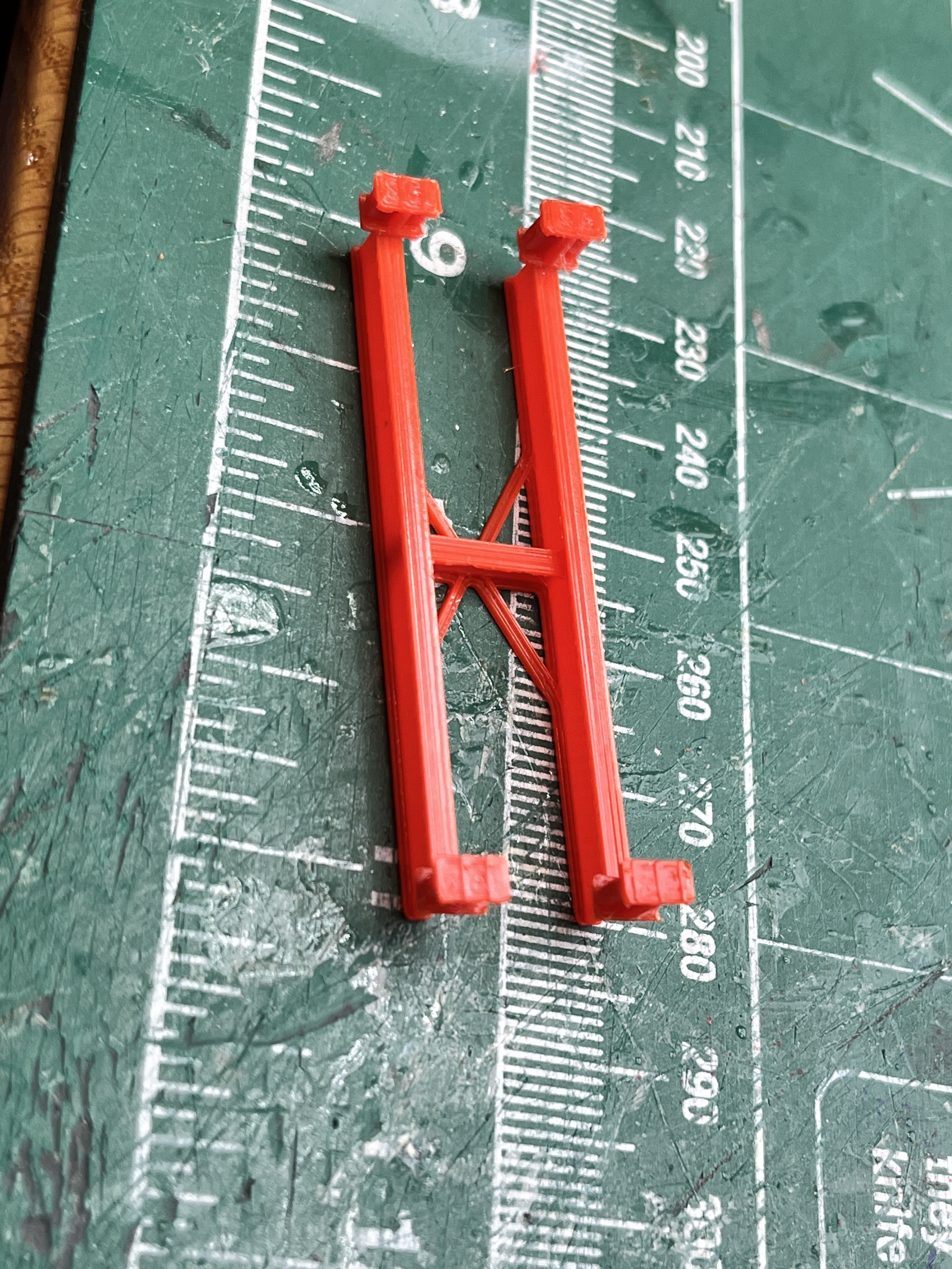
The crane boom parts are labeled based on the original drawings. Notice that below the side view there are circled numbers starting with 1. These numbers go up to 9 which is the end of the boom. These are the section numbers I use.
The parts are really thin and delicate when you take them off the print plate. Most of the angle beams are 2x2x0.8mm thick. Once the entire structure is glued up it is surprisingly strong.
Once the boom is glued up, remove the temporary cross supports that align the two rails. At this point set the trolley in place and tilt the boom back and forth making sure the trolley rolls along the rails. I had an issue at section 5. When I looked down the rails, one of them pinched in a bit. The rail positions are controlled by the cross beams. I had to unglue the cross beam on the side that was pinched, straightened out the rail and reglue it. Now the trolley rolls along the rails end to end when I tilt the boom. Here is a picture of the underside of the fixed rails.

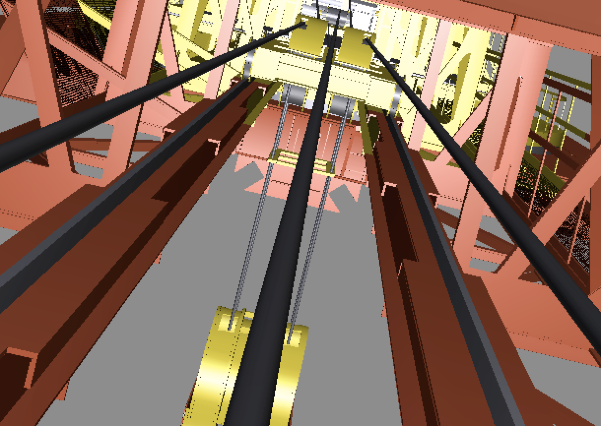
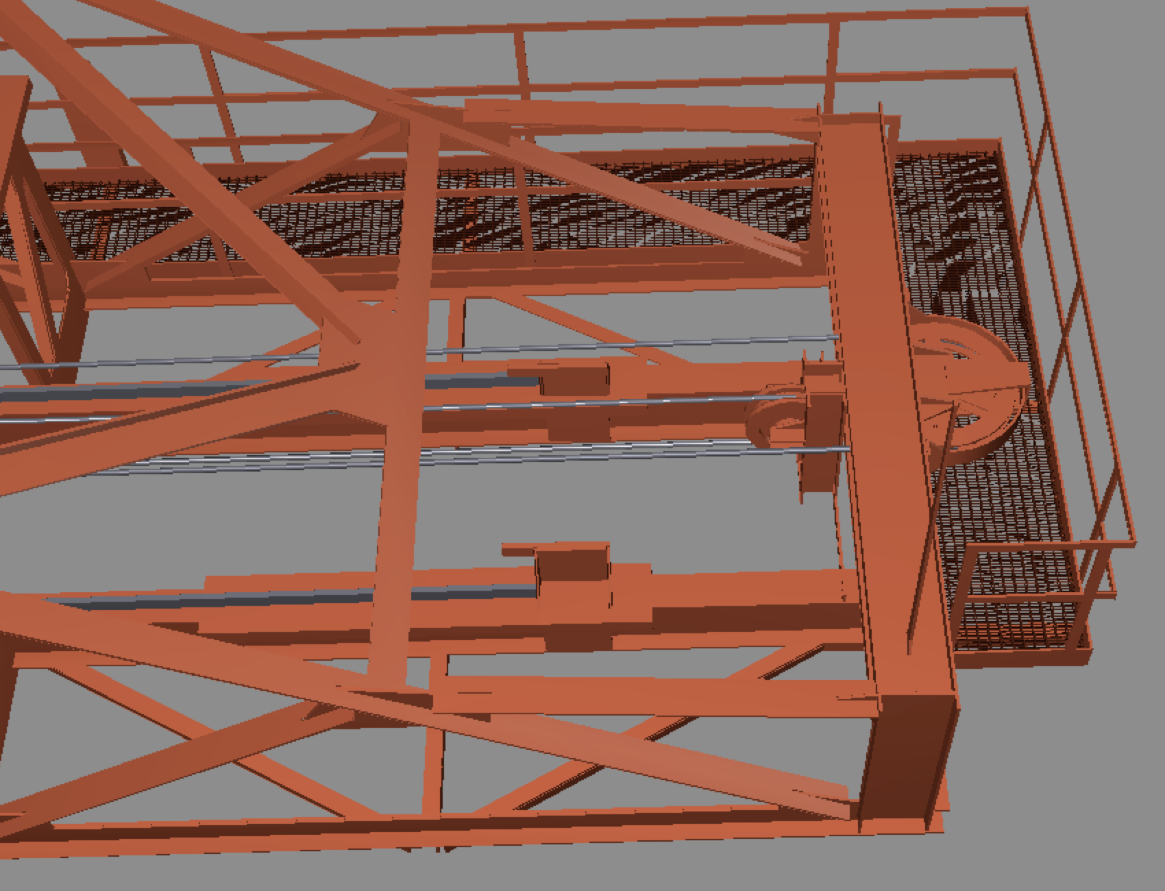
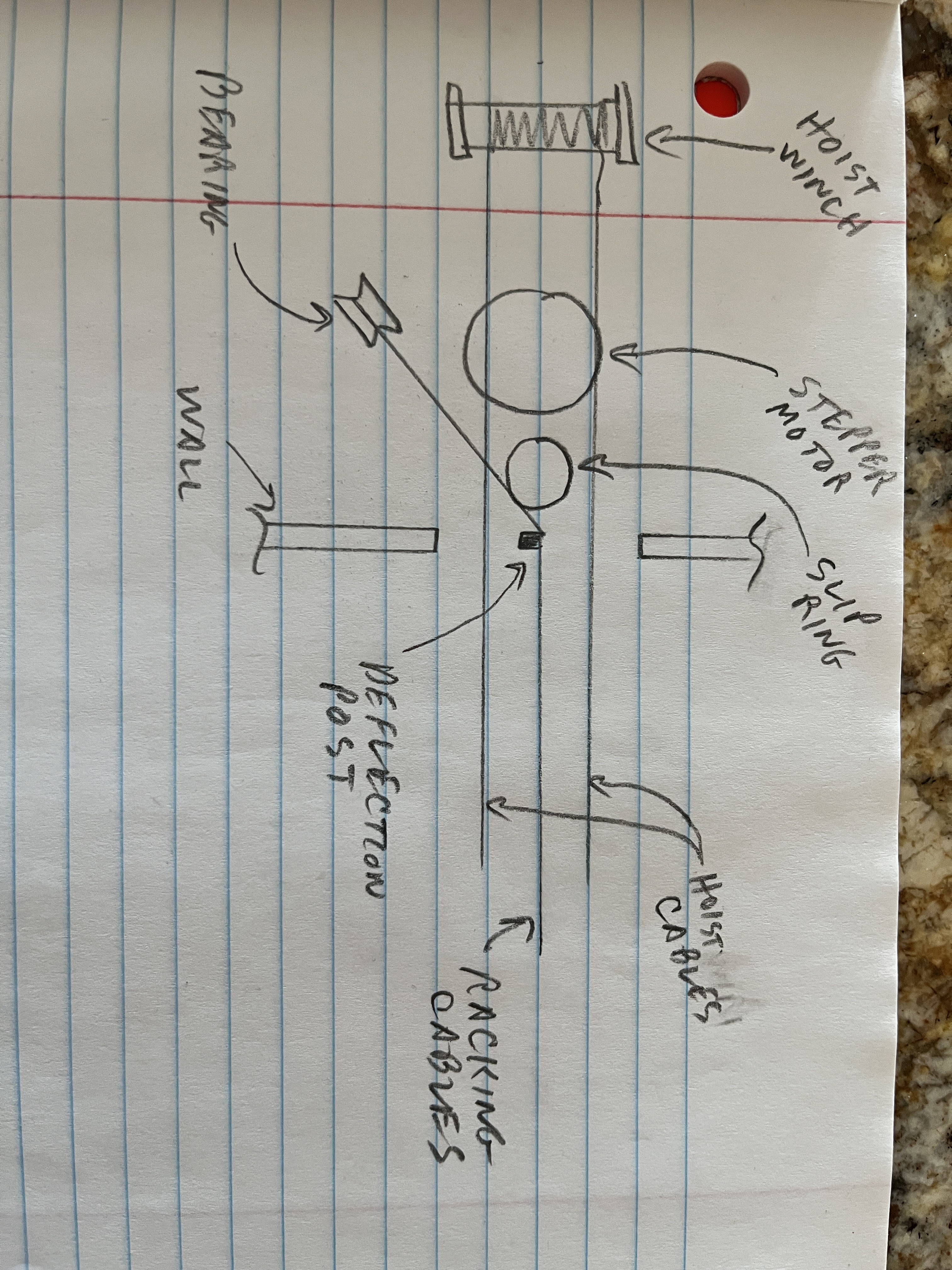
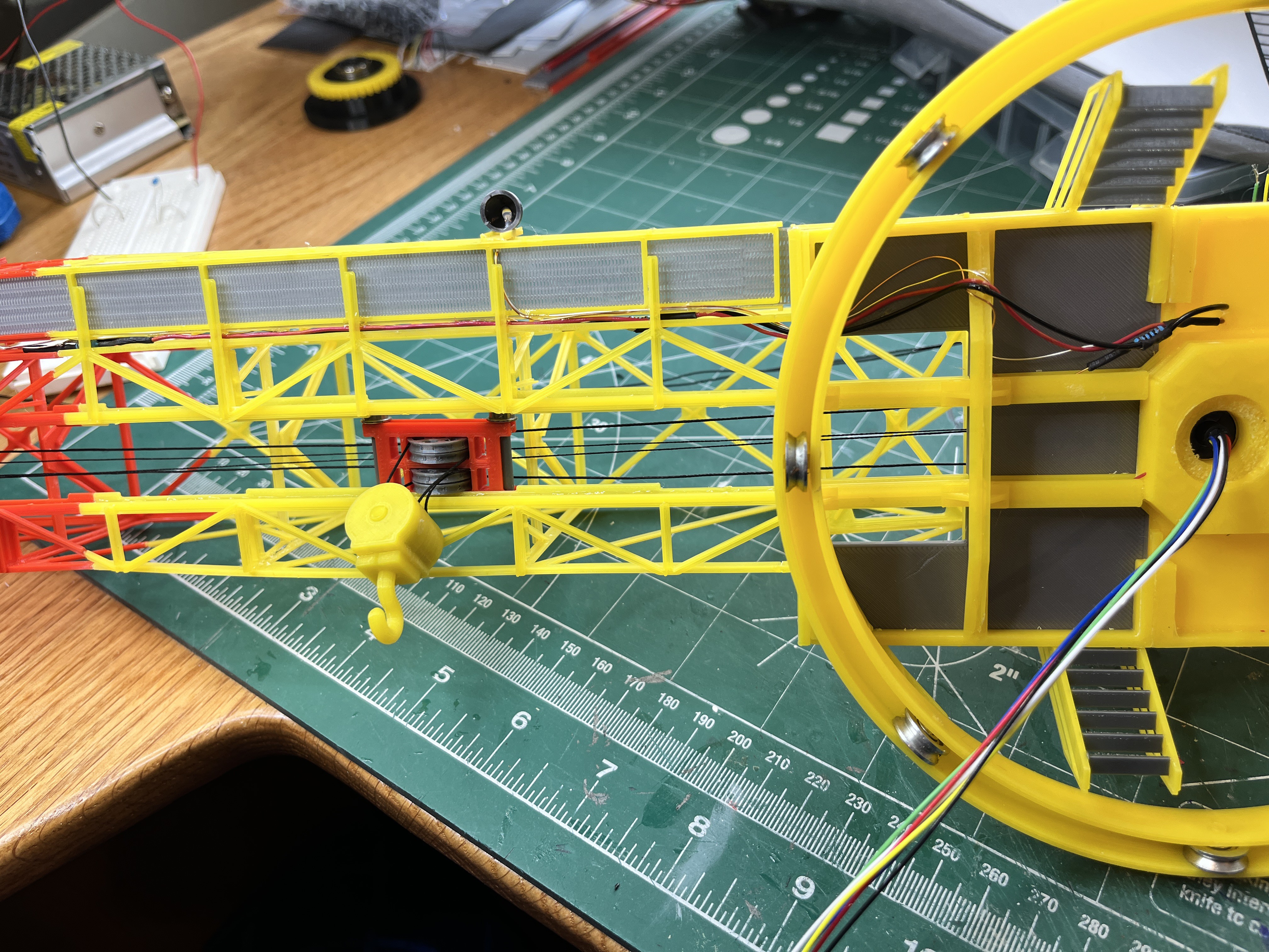
Before I glue the boom to the machinery house there are few parts that need to be addressed while access is easy. There are four cables that go from the machinery house out to the boom; two hoist cables and two racking cables. The hoist cables are easy because they will go around the slip ring and over the stepper motor to the hoist winch. These two cables are aligned horizontally. The racking cables are a bit more interesting. These two cables are aligned vertically and should go right through the middle of the opening. The lower one is attached to the middle of the trolley so after it enters the opening the slip ring is in the way. Since this cable will not be automated my solution is to add a vertical deflection post to redirect the cables over at an angle to an interior pulley. This will be hard to photograph once installed so I drew a quick picture of the layout.
Here is a three dimensional layout or reeving diagram of the cable runs.
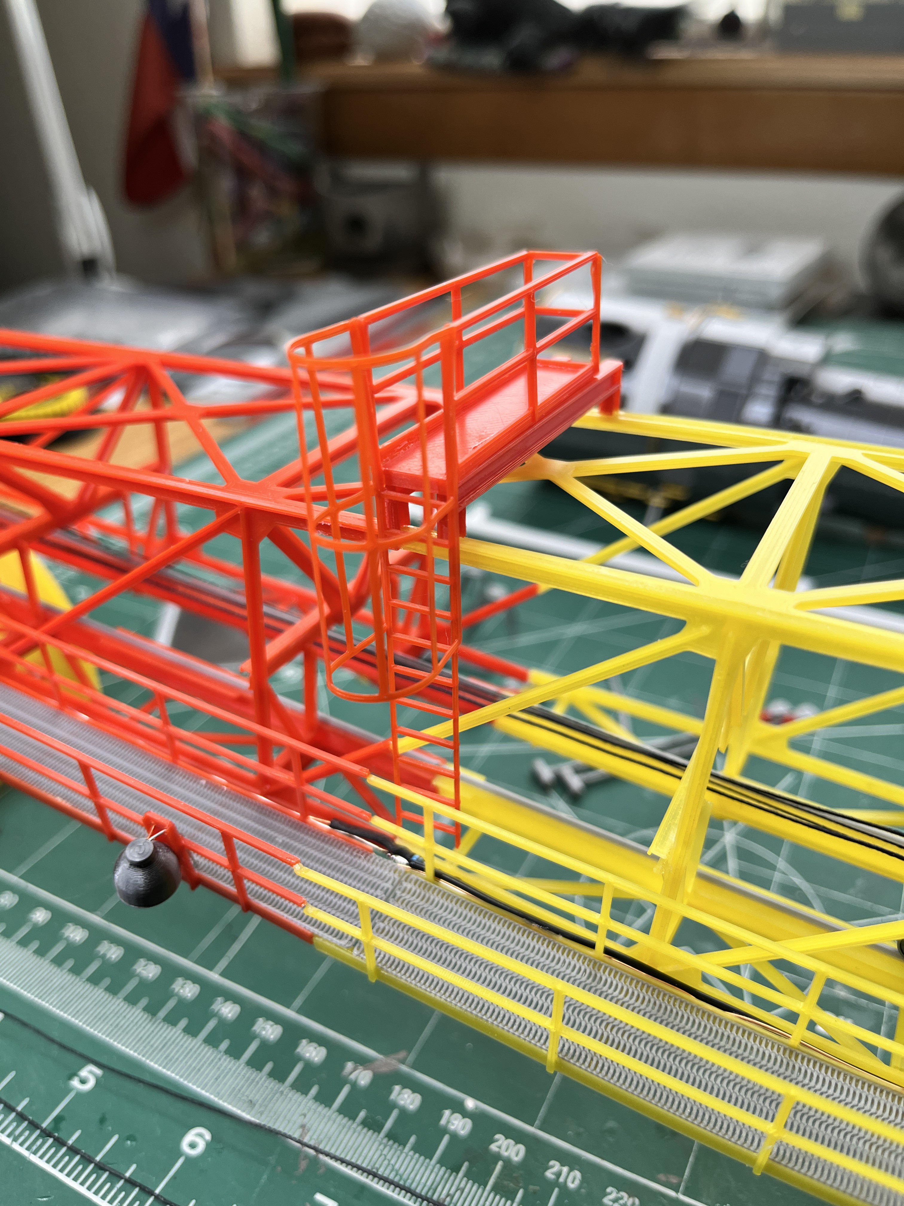
Here is a picture of the cable deflector as well as the upper platform. Notice that the floor grating is actual grating. For the stair steps instead of printing grating I built the steps as I did for the LUT and did a filament change to get the correct color.


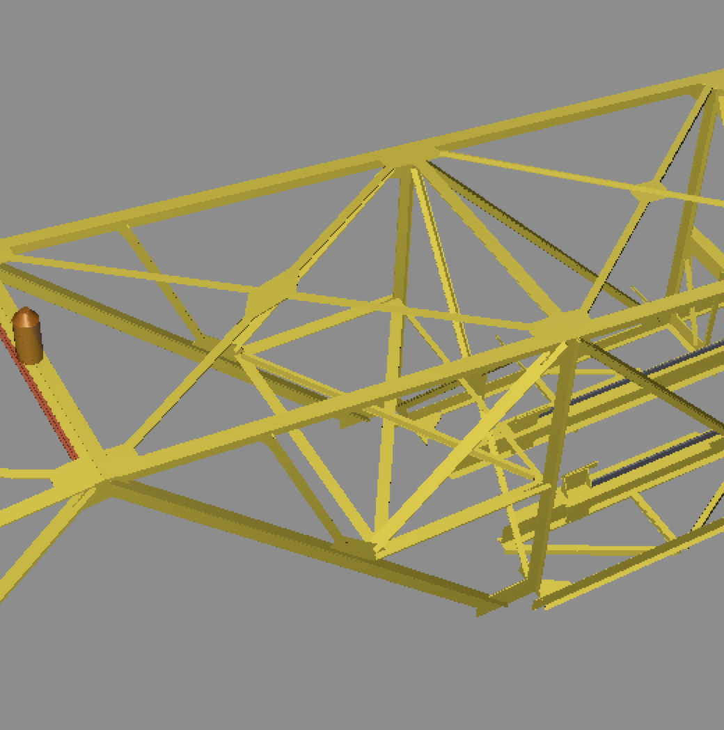
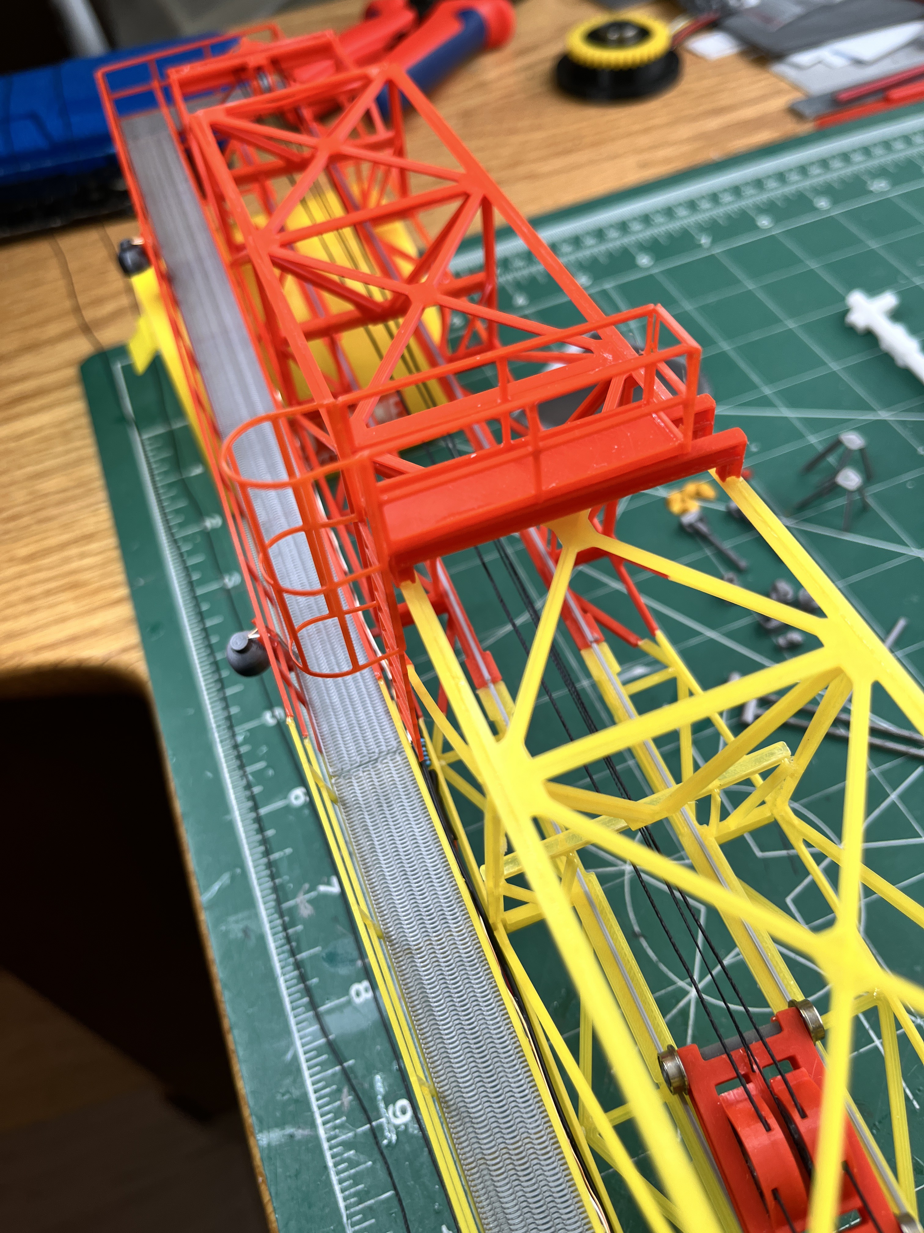
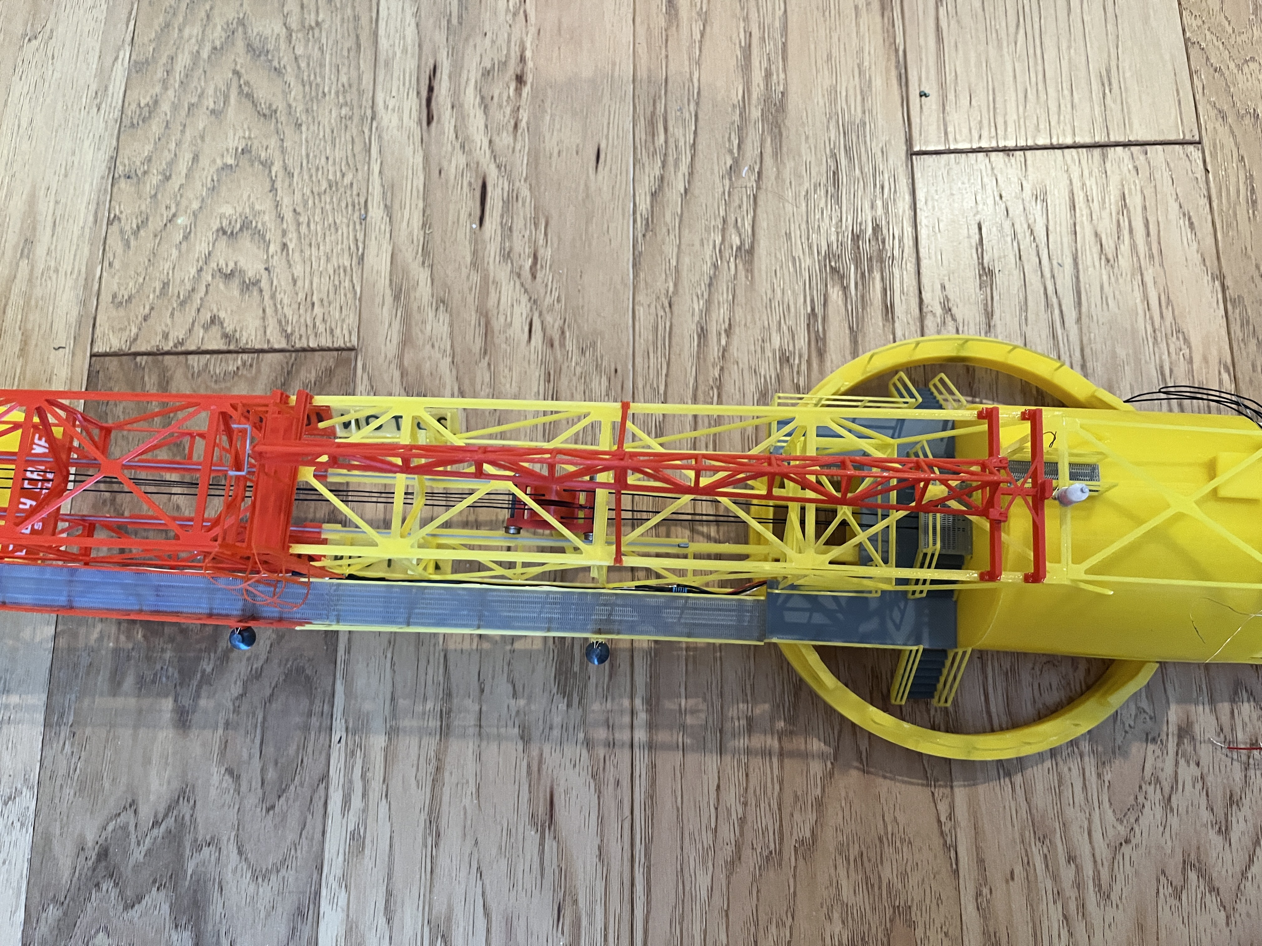
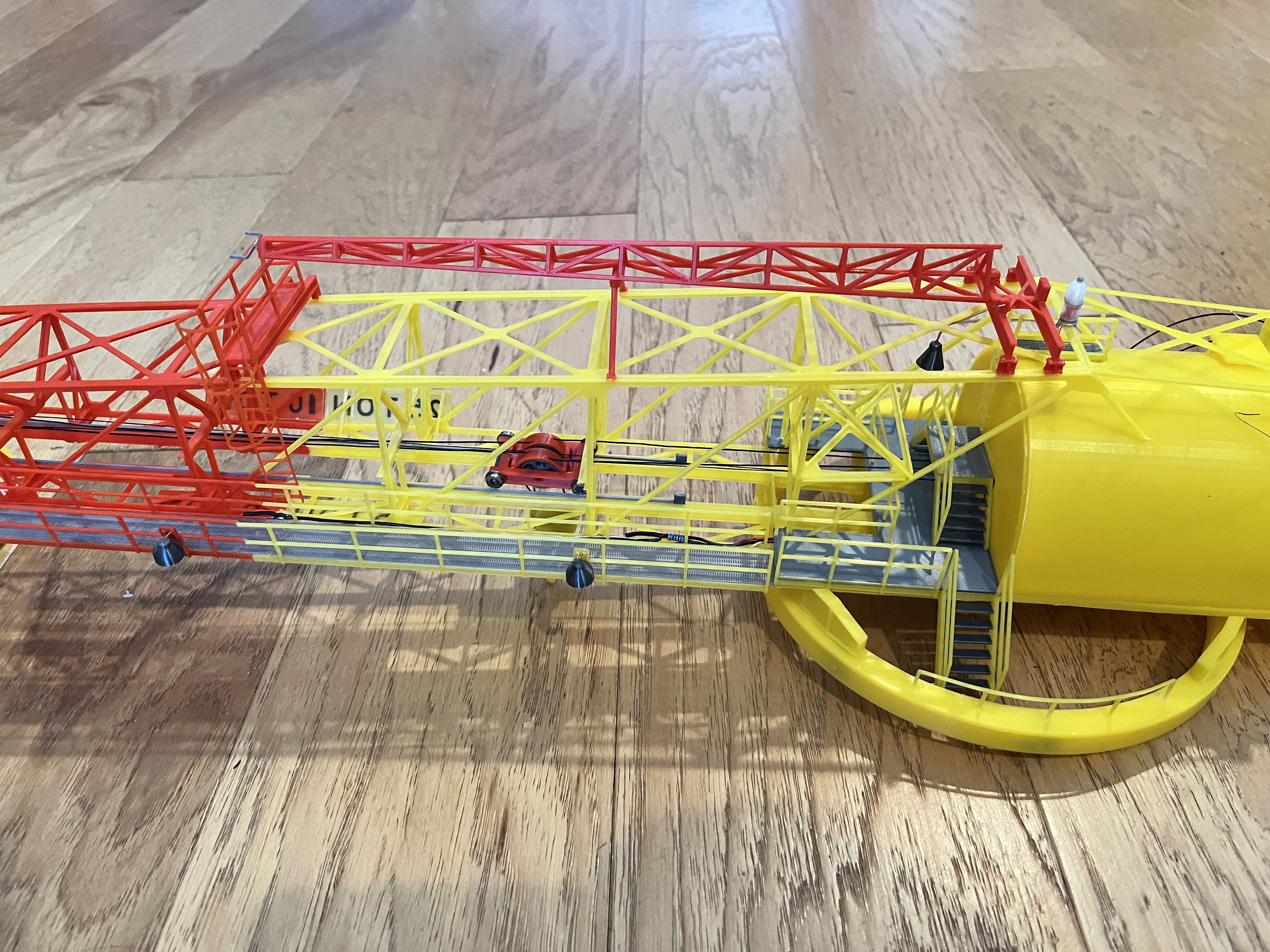
The boom is now attached. It is light and airy but surprisingly strong. My initial thought was I would have to add real weights such as washers inside the end of the machinery room to offset the weight of the boom. As it turns out the hoist servo weighs enough that it more than offsets the boom. You can see in the last photo that CarrierBeam1A has holes for the old boom lower rails which no longer line up with the new boom. I will correct this part but probably not go back and fix my version. From this photo you can see how much smaller my boom C-beams are. Mine are more accurate so the crane looks more accurate and to scale.
Here is the trolley all roped up. It was a bit tedious. Once everything was roughly roped up with the ropes untangled I then glued together the two halves of the hoist and glued on the two top rope guides. As long as no equalization is required, the hoist operates on the two outer pulleys of the trolley. Only when moving the trolley does the inner trolley pulleys move.

Here is the walkway. I have not yet glued it on until I figure out where the lighting wires will run. I am going to try out some micro LEDs. I want the wires to be as hidden as possible. The wires will probably run between the boom and the walkway.


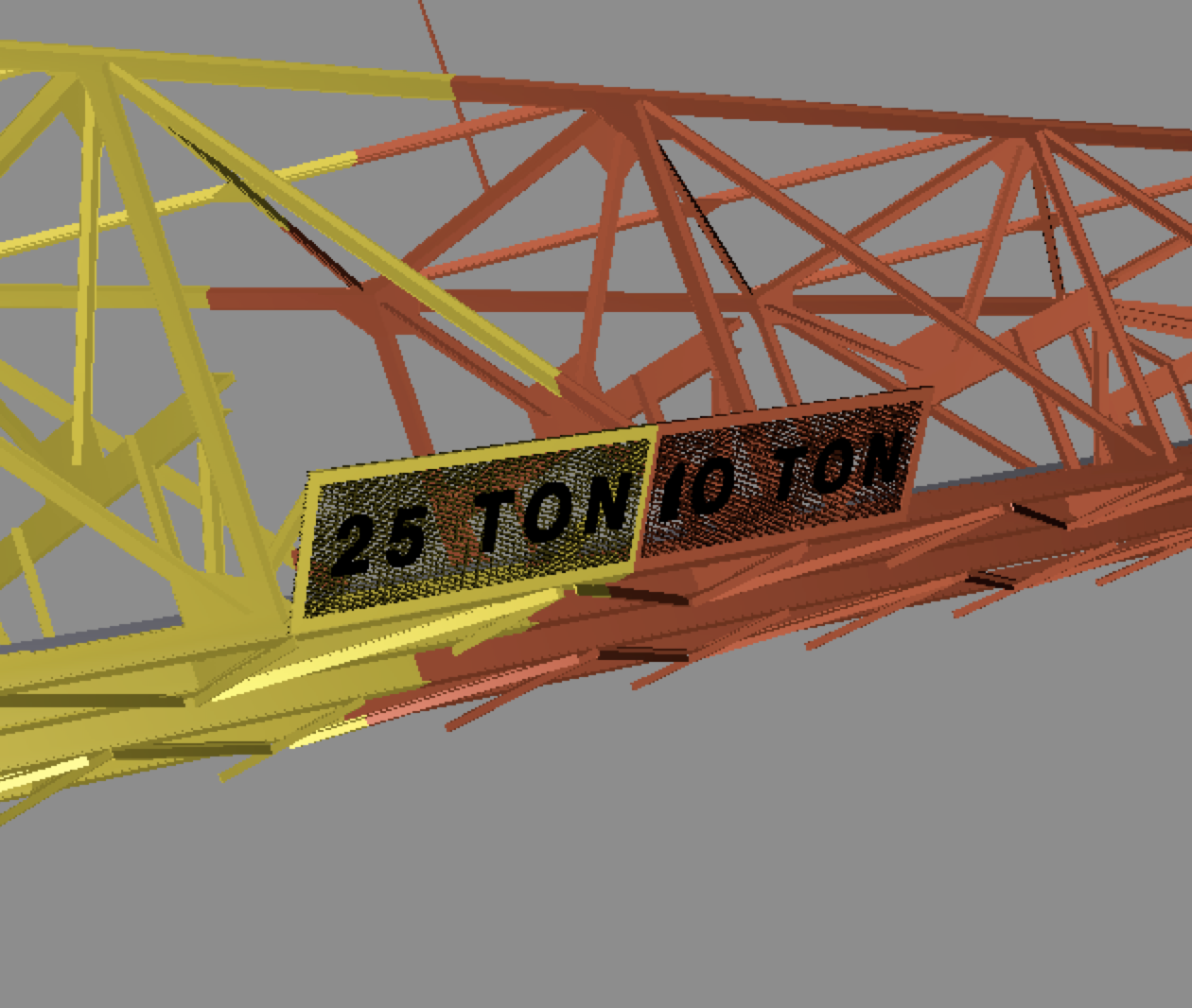
Here's a question for y'all. The sign on the crane "25 Ton | 10 Ton" has a perforated plate background according to the Cato field notes with the color of this background plate as sea green. The pictures of the crane in the museum show this plate as yellow/red. The MicroArtwork shows the plate as black. I'm thinking it is either sea green or yellow/red. I can't seem to find a definitive picture of this sign back in the day. The museum more than likely repainted the crane before displaying it. Does anyone have the answer???
George wrote: His 1992 field notes about the sign also mentioned the 10 Ton end (red) as having a yellow background which doesn't make sense. I'd say it was yellow (25Ton) / red (10Ton) because back in the day that's how it would have been painted, nothing fancy.
Here are the Colby Crane signs printed with the new printer, elephant foot compensation turned off. This is a much better result. These are only two layers thick.
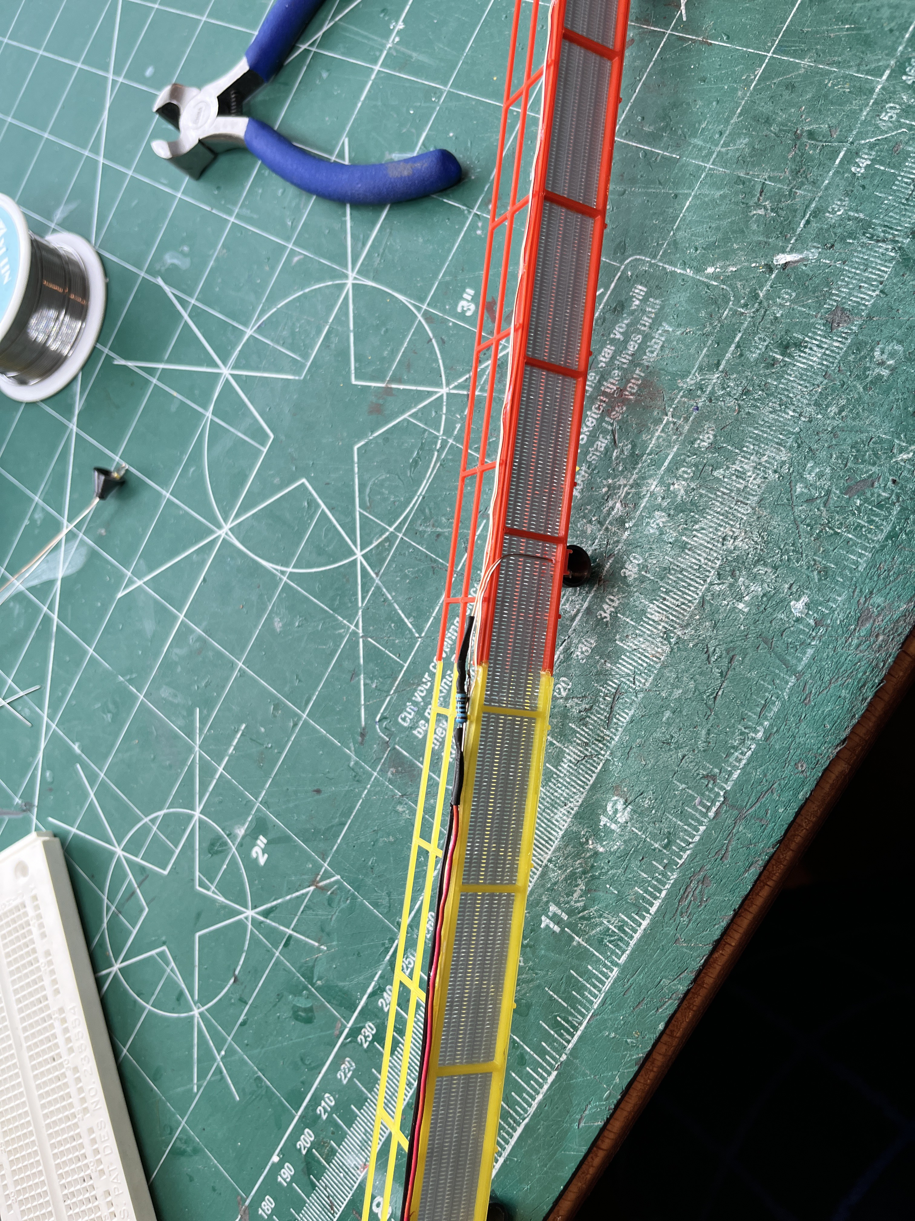
Here are the boom lights installed. I really like the micro LEDs, not because of the LED but because of the tiny wires.

Here are the wires glued to the inside edge of the walkway.
And here is the walkway glued on. This is the underside of the boom since that is what is the most visible. Note that the wires inside the roller circle will not be visible.
And then there is a fourth light, the platform light. Once I put on the ladder to the roof and the associated platform I will then route the wires to this will hide the wires.
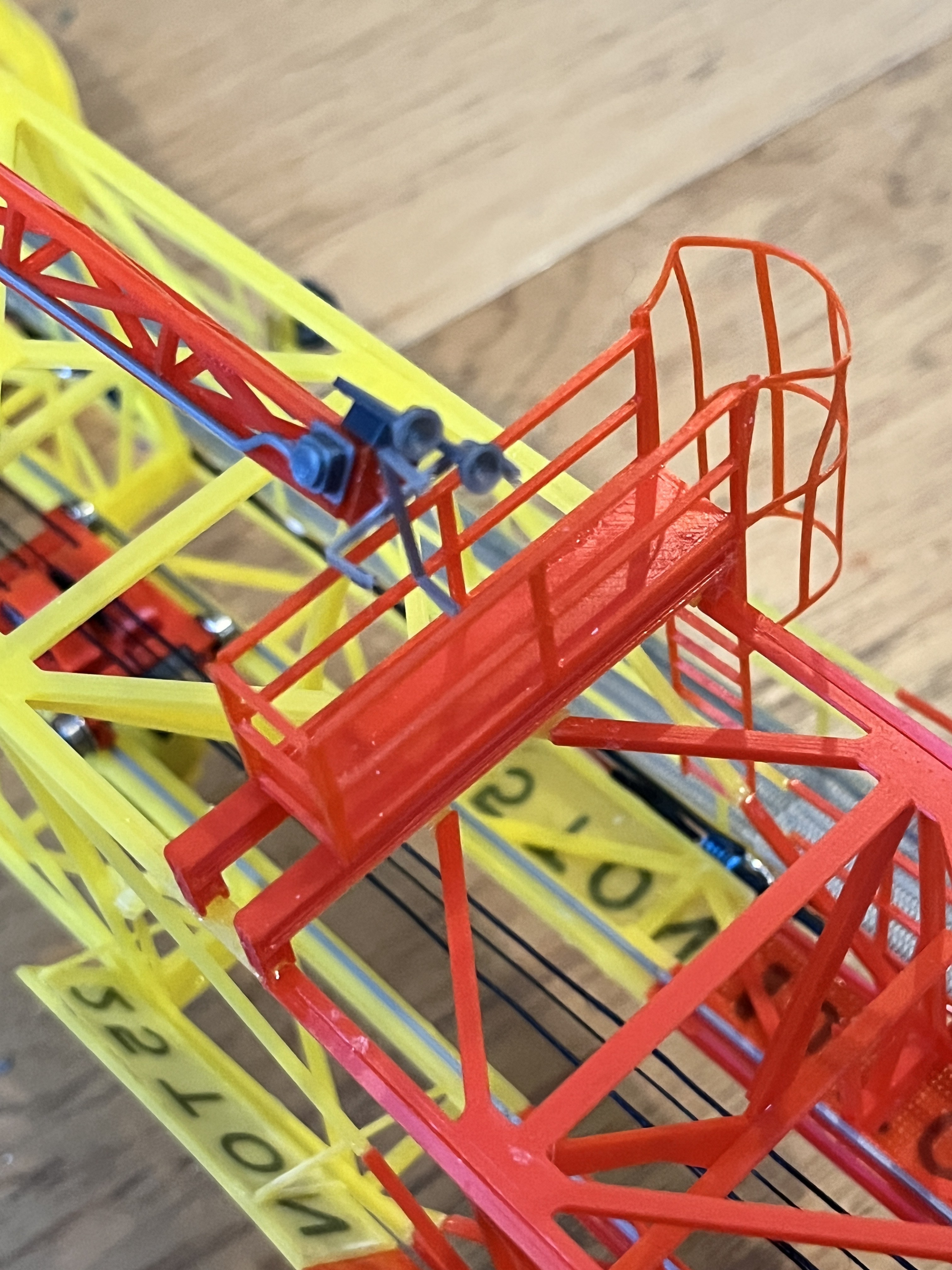
Here is the catwalk. Notice that instead of creating the cage as 9 separate parts and trying to get them to line up I chose to print it as one part that is only 2 layers thick. It is easily bendable, just glue it to the two sides of the ladder. Both this ladder and the other one are really thin and fragile but are more to scale.
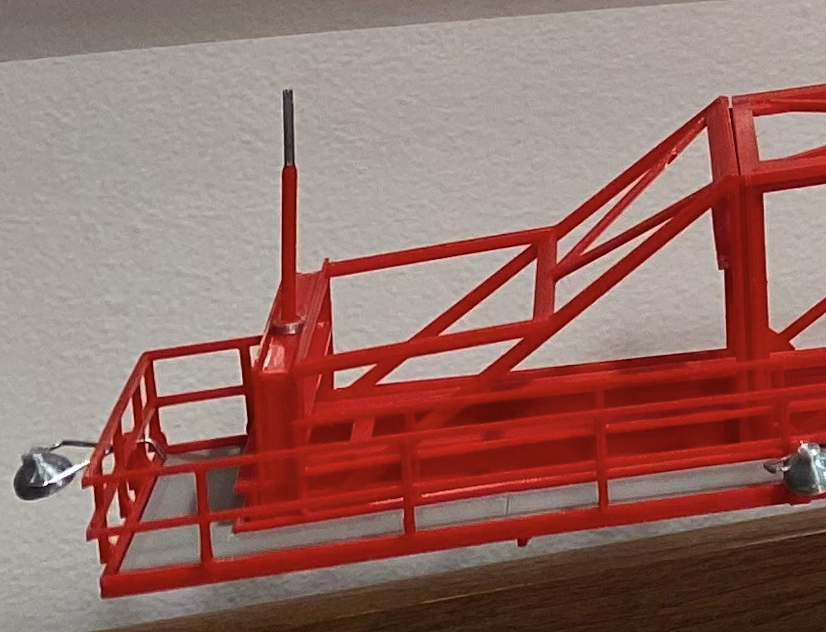
I am looking at the "air terminals" (another term for lightning rods) on the top of the crane. The as built drawing of record shows a specific number; 2 on the roof, and then at sections 3, 5, 7 & 9. They are also all at the same height. Both the MicroArtwork and TurboSquid have fewer and they are not at the same height. In the enlarged picture I can just see these terminals and they agree with the as built drawing. The end one at section 9 and the 2 on the roof are centered. The others at sections 3, 5 & 7 alternate from side to side. The way I will model these is since the upper portion is really skinny and metal, about the side of a sewing pin, I will use sewing pins with the heads cut off as the top end.
George wrote: Docs callout Air Terminals as Thompson 664 or equivalent 1/2" diameter or .2mm at 1/60th scale. Looks like they only make them 3/8" now.

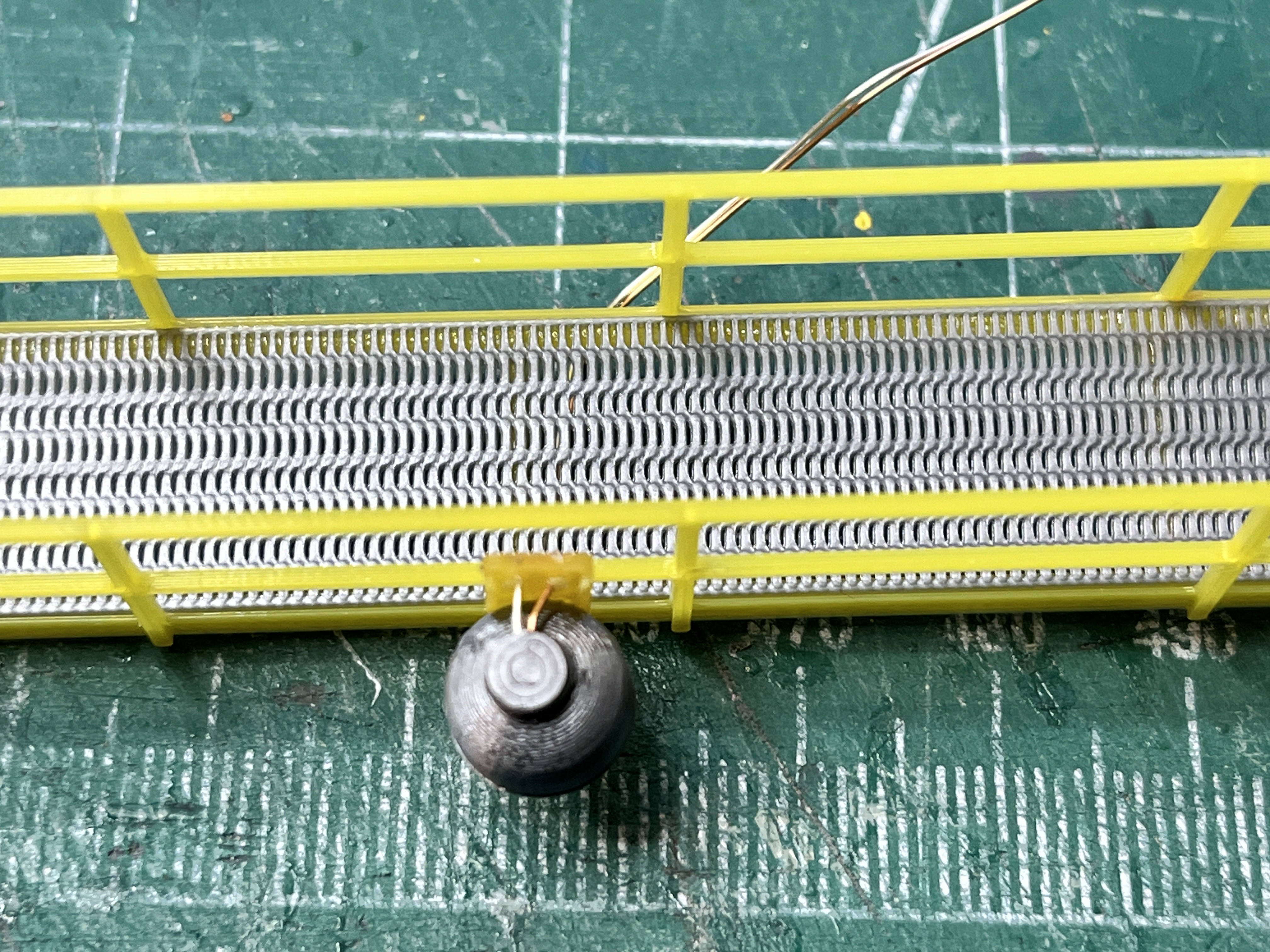
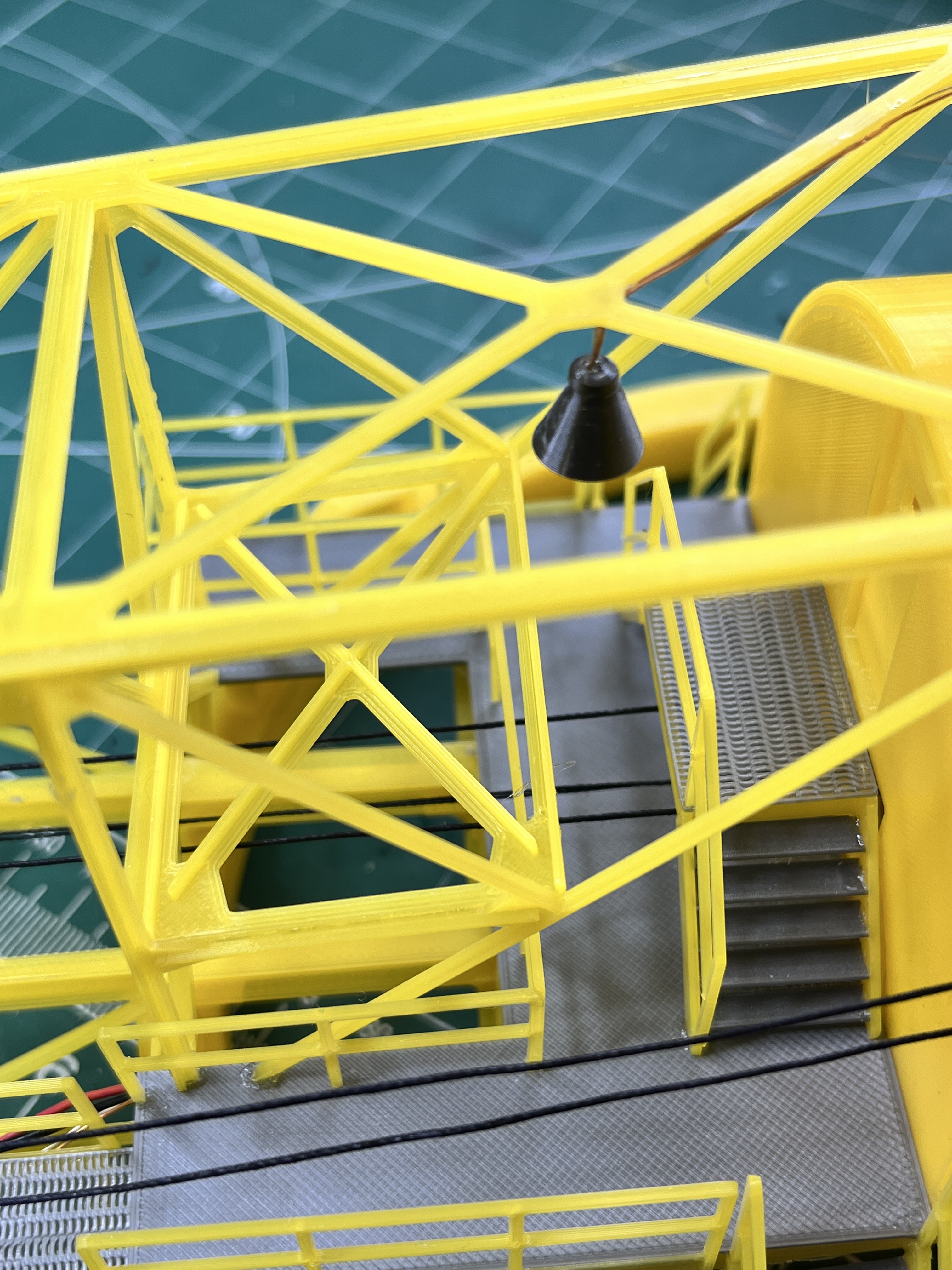
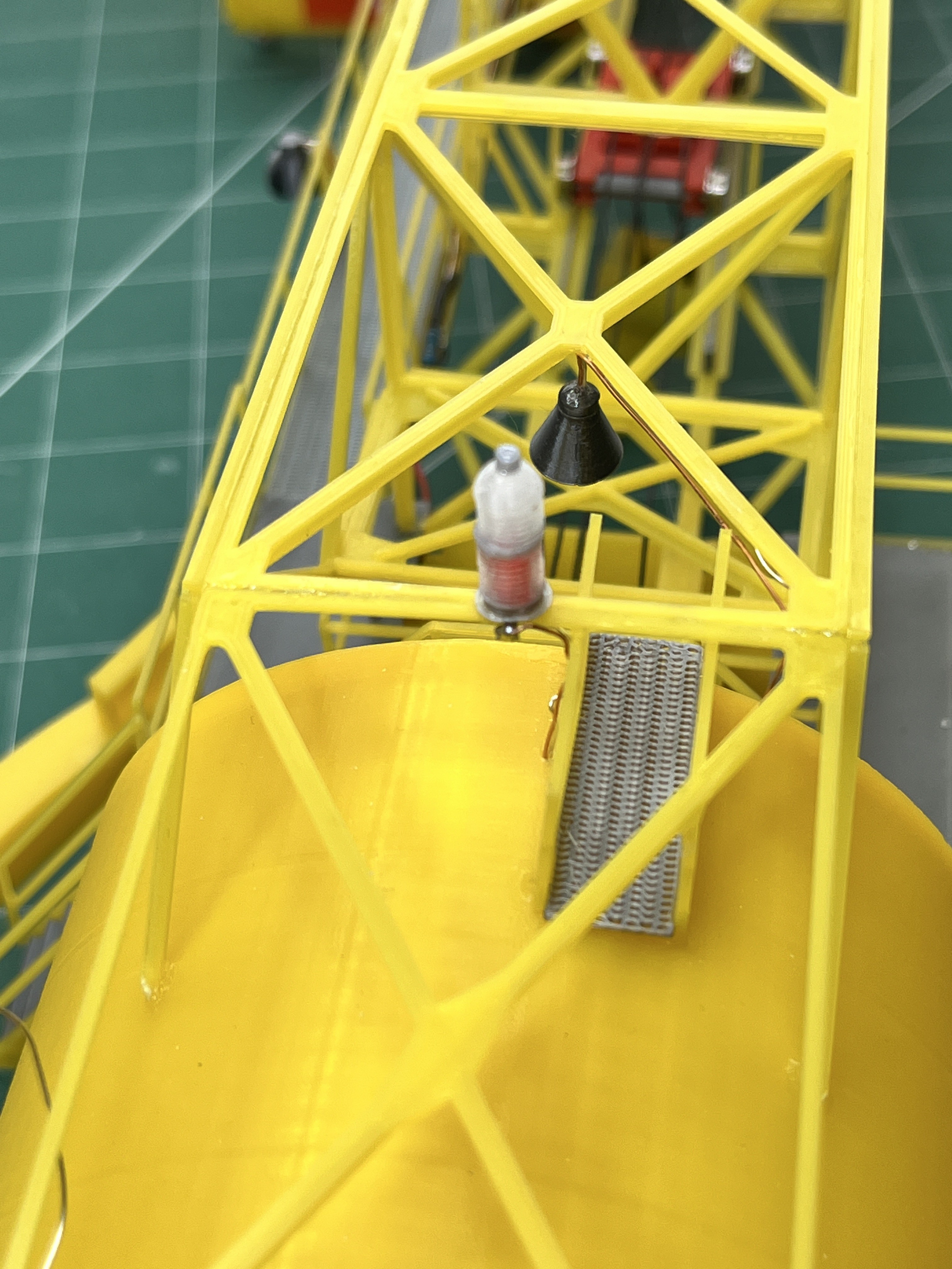
The beacon is installed. Notice that I cut the wires off one of the micro LEDs since they are so thin and soldered those on.
I also installed the signage, properly angled with angle braces.
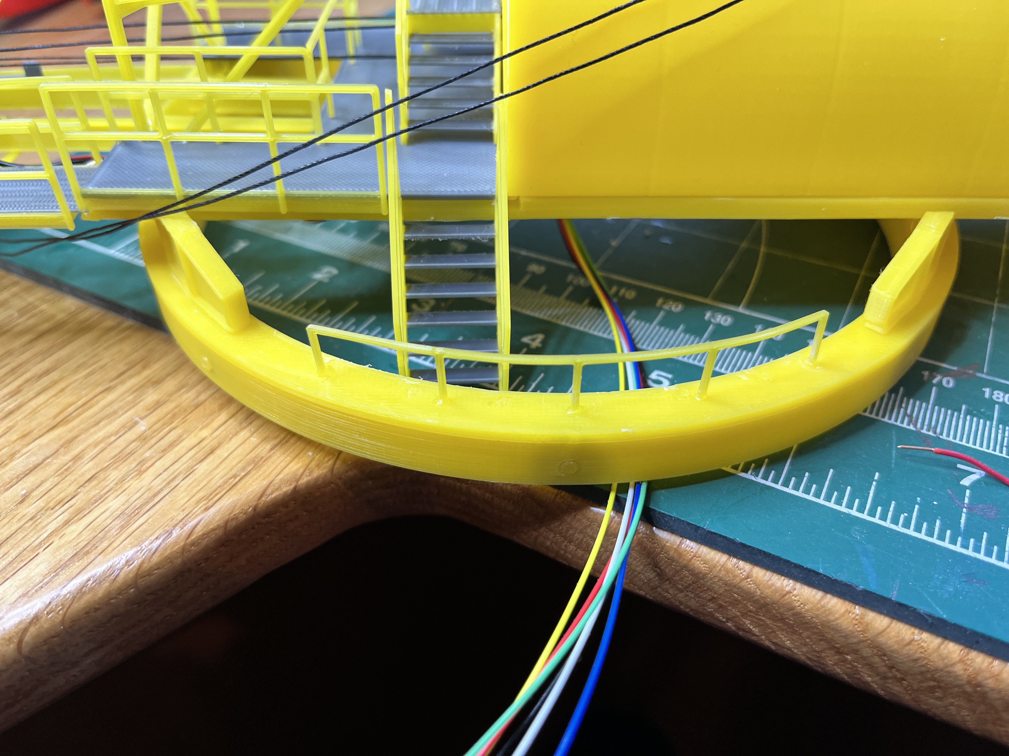
One thing I have learned over the last two years is not to stick with one source such as MicroArtwork or TurboSquid. You may end up with some inaccuracies. For the most part MicroArtwork is more accurate than TurboSquid, but here is an example where MicroArtwork is incorrect. There are railings on the roller circle. I can see them on the drawings but they are not drawn in detail so I looked at other people's work. The first picture is from MicroArtwork. It shows 3 sections with 4 posts. The next picture is TurboSquid that has 4 sections and 5 posts. The definitive picture, thanks to George, is the third one that agrees with TurboSquid.
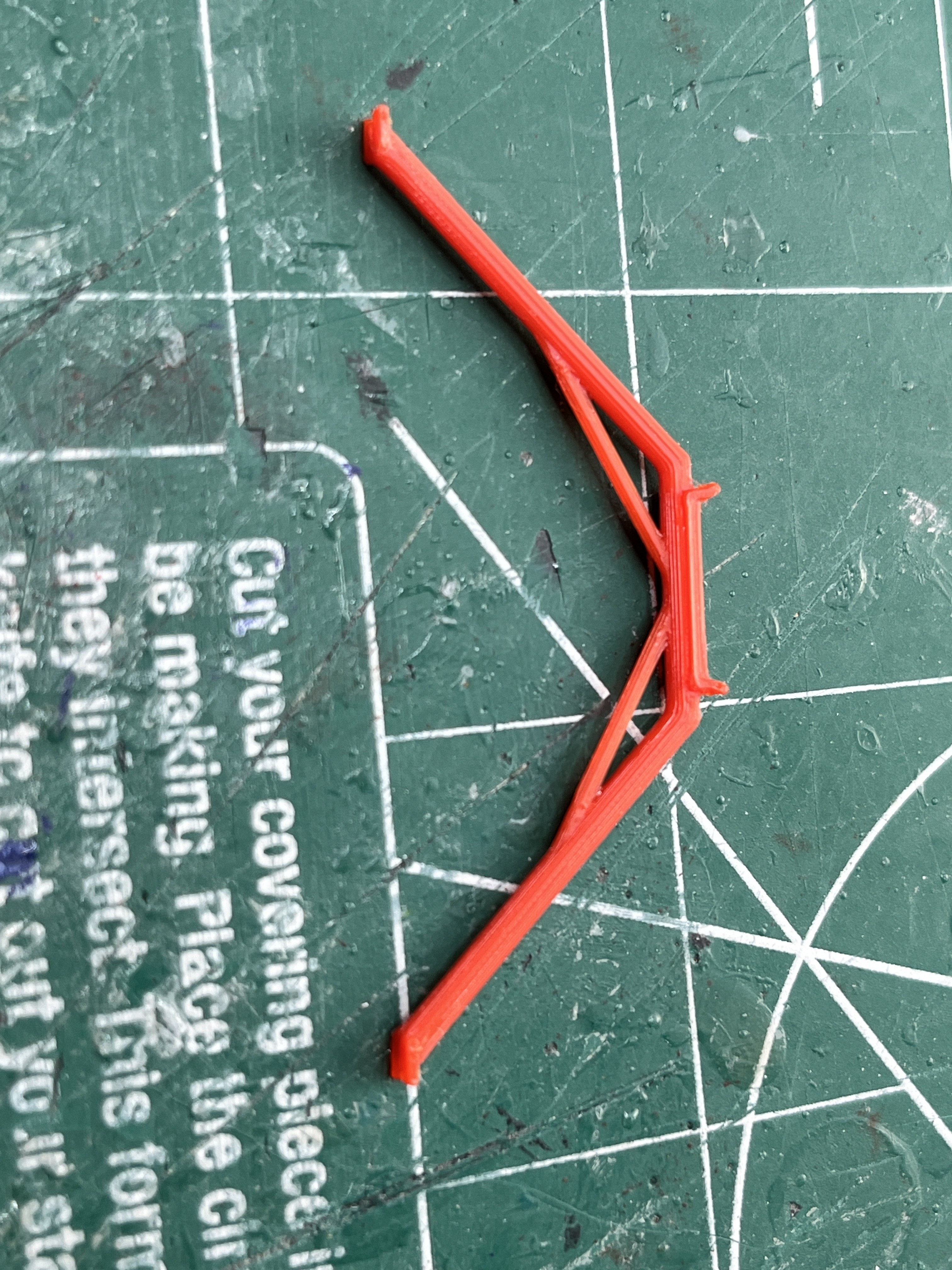
After all that I created a one piece rail (one on each side) that is to scale and is easily bent into a curved shape. This is much better than fiddling with trying to line up very small parts. Here is my solution.
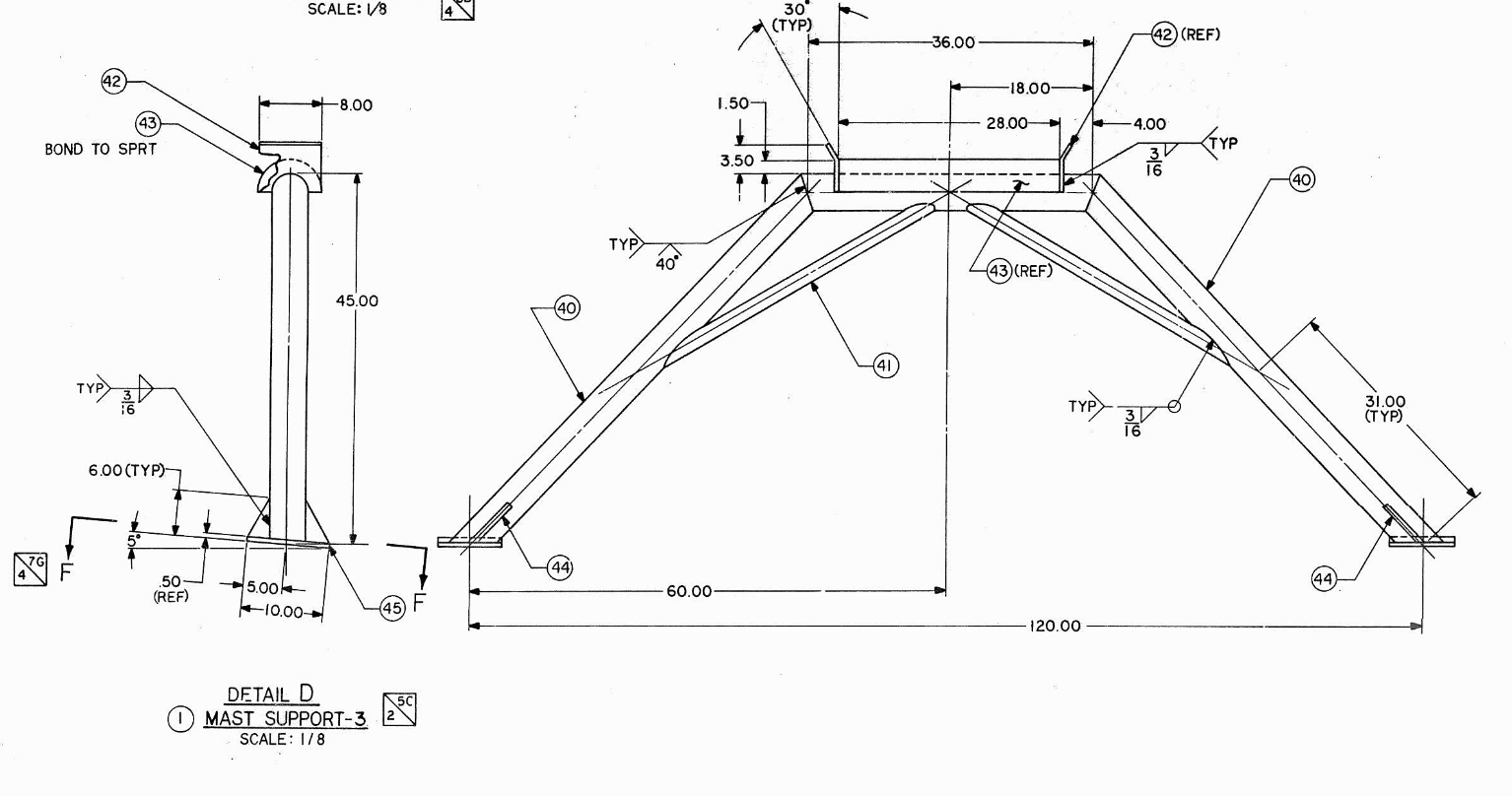
Here are some of the parts that make up the lightning mast. I'm not sure why people over simplify parts such as this boom support. Here is a picture of the ChristineZ part. It looks like something out of Minecraft or made from Legos.
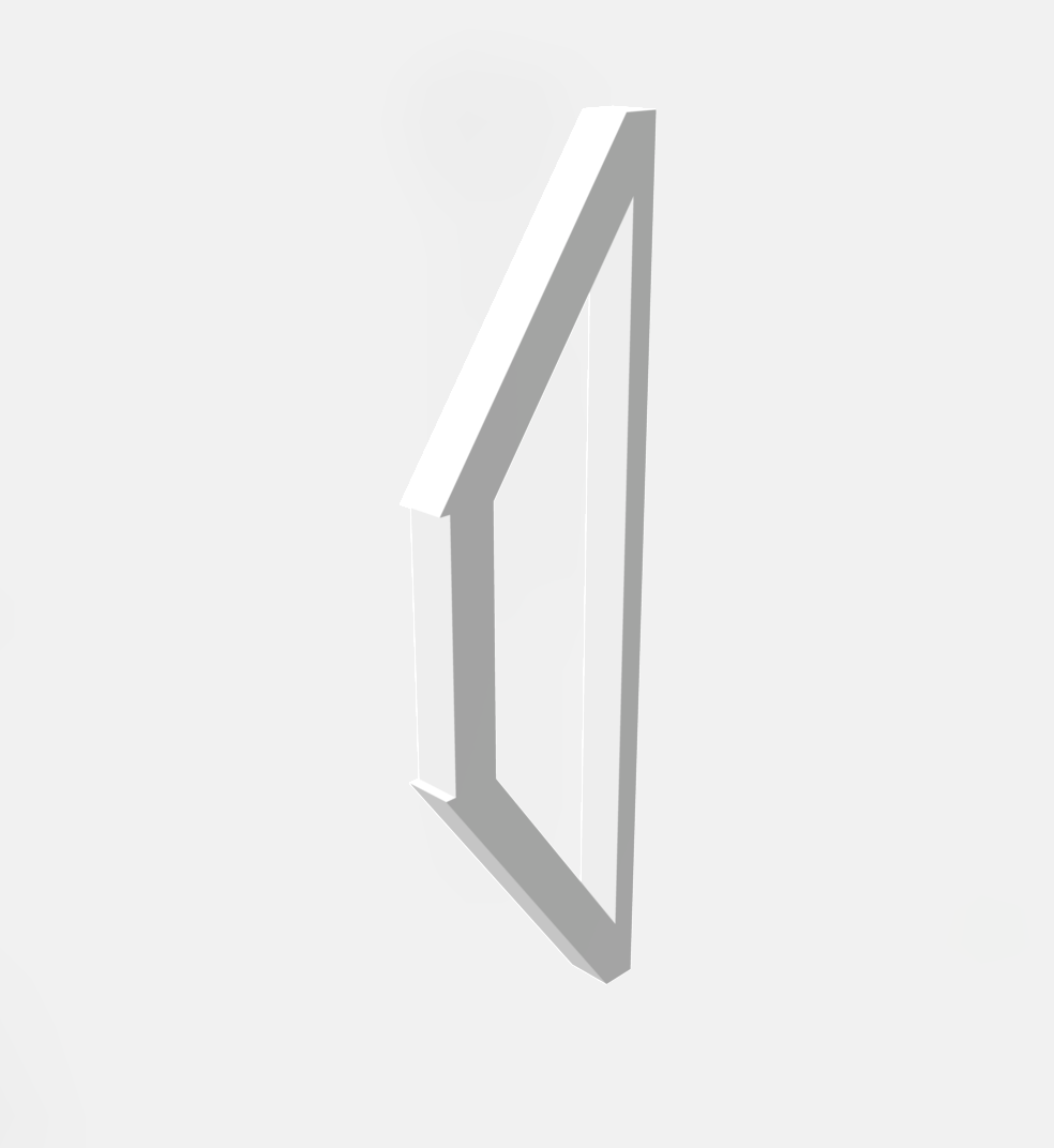
Here is the original as built drawing and my part. The support is made to the specifications in the documentation. I see no reason not to build the correct part as long as the part is large enough to print. In the spreadsheet it shows to print two of these parts. That is because the part to print is half of the part. Since this part is symmetrical, simply print two halves and glue them together.
Here are the small hinges. The hole through the hinge parts is intentionally small. Select a small wire or paperclip and drill the holes to the correct size. The smaller the wire the better. Here you can see I used a 0.025" or 72 drill bit. It helps to have a set of really small drill bits when modeling.

And here is the mast base which is printed as one part upside down.
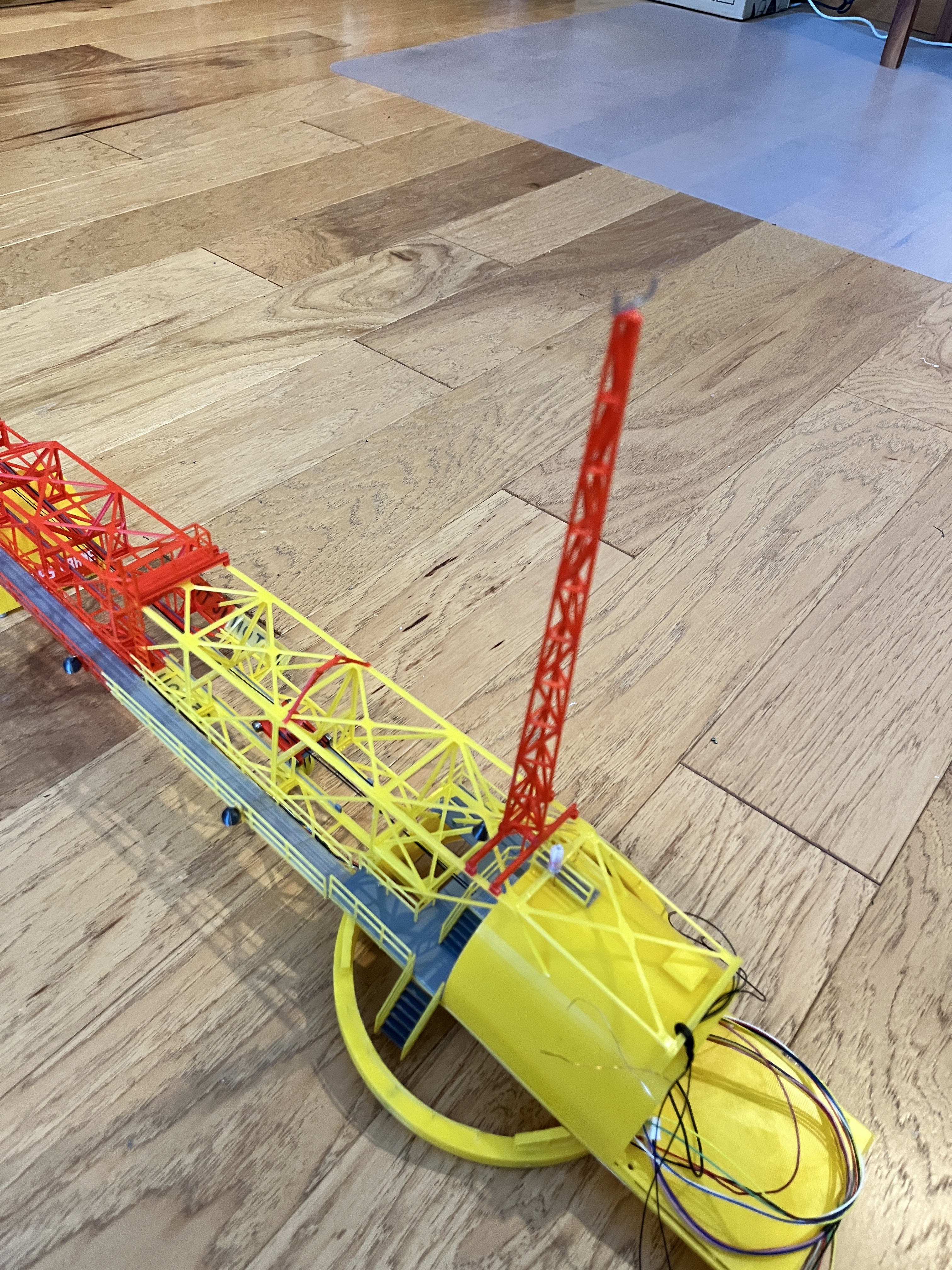
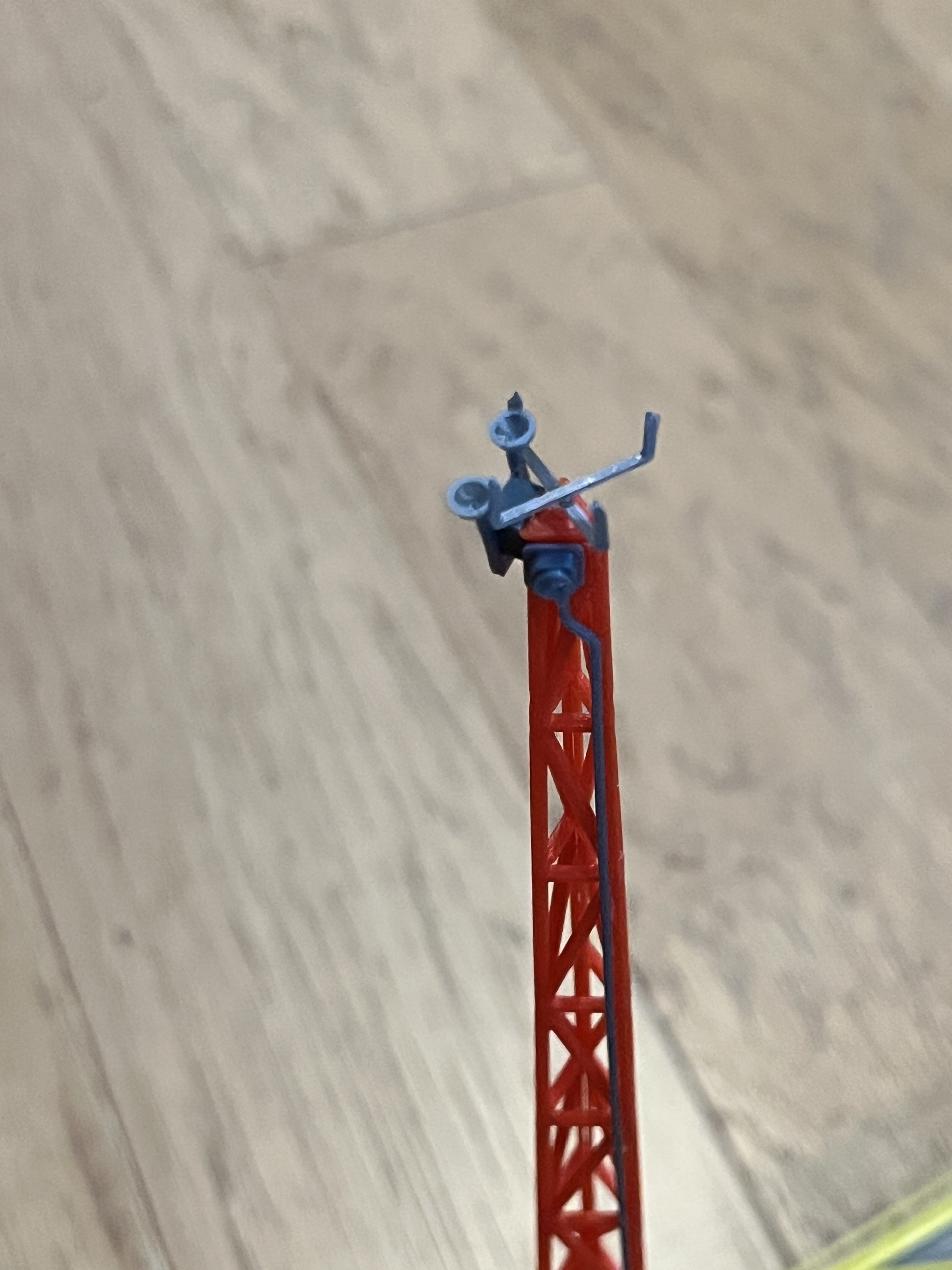
And here is the finished mast. You can see I added an anemometer to the top of the mast. Im not sure if this is correct but it makes sense to me and I have seen it in various works. The mast when lying down lined up perfectly with the catwalk which is obviously there to maintain the equipment at the end of the mast.
George wrote: Looks really good Bill! There were at least two Anemometers, probably temp and air pressure as well.

Thanks for the picture. I need to add another gizmo or two. This adds more credence to the air terminals all being the same height. I assume you don't want lightning to strike this "lightning mast" given all the instrumentation on top. With the mast laying down the air terminals will all be above the mast, protecting it from a strike. It seems like this mast would be more appropriately called the weather mast or instrumentation mast.
Here is the completed mast with all the gizmos and gadgets. Not sure what they all are but its the fine detail that makes a model. You can see there is a steel pipe going down the side of the mast along with what looks like a junction box and some other box on the other side with two dish looking things, plus an added anemometer. Both of them form a cross.
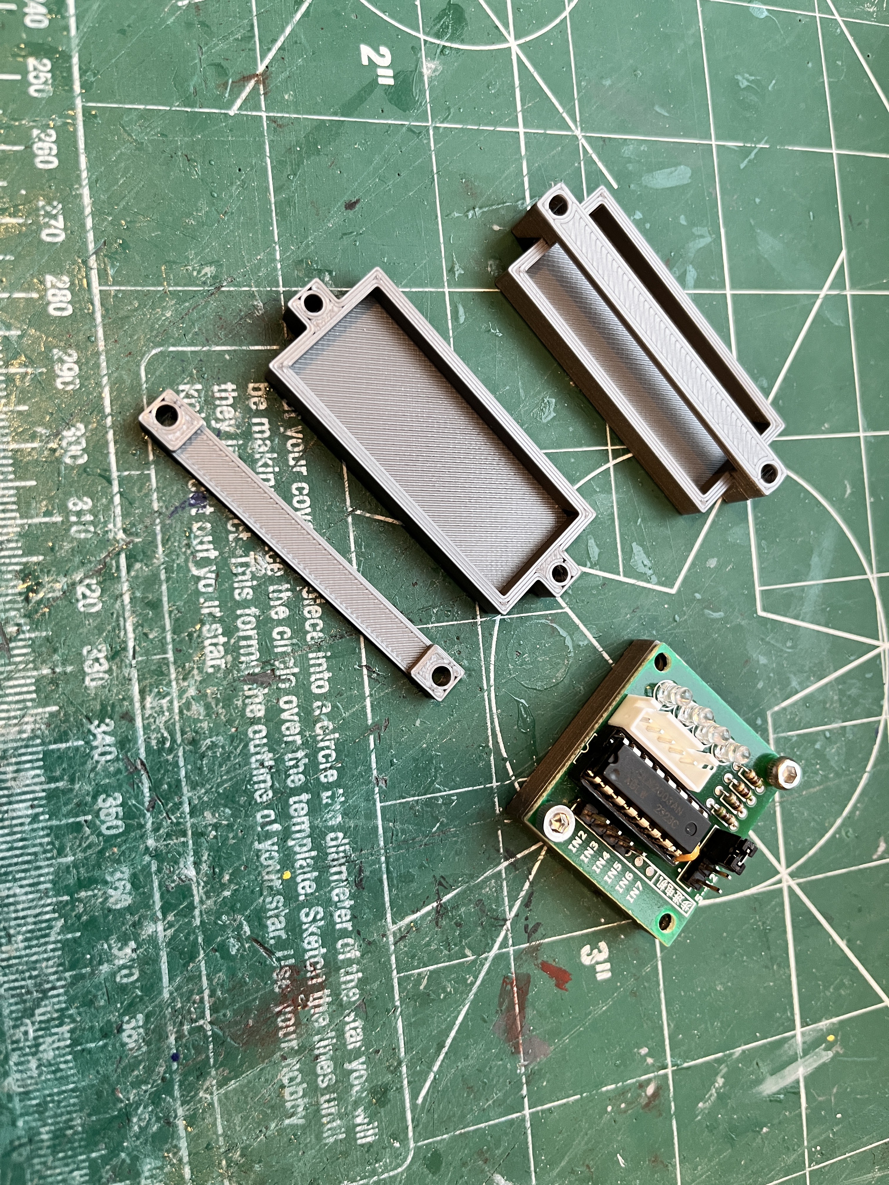
I have been working on the control box and circuitry. Both the Arduinos and the stepper motor controller boards have mounts. The controller board has an indent so the board sits flush on top. Two screws should be enough. The Arduino has mounting holes that are so small I chose to use a cross strap to hold it in instead of fiddling with such small screws. Both these mounts have flat bottoms that can be glued in place.
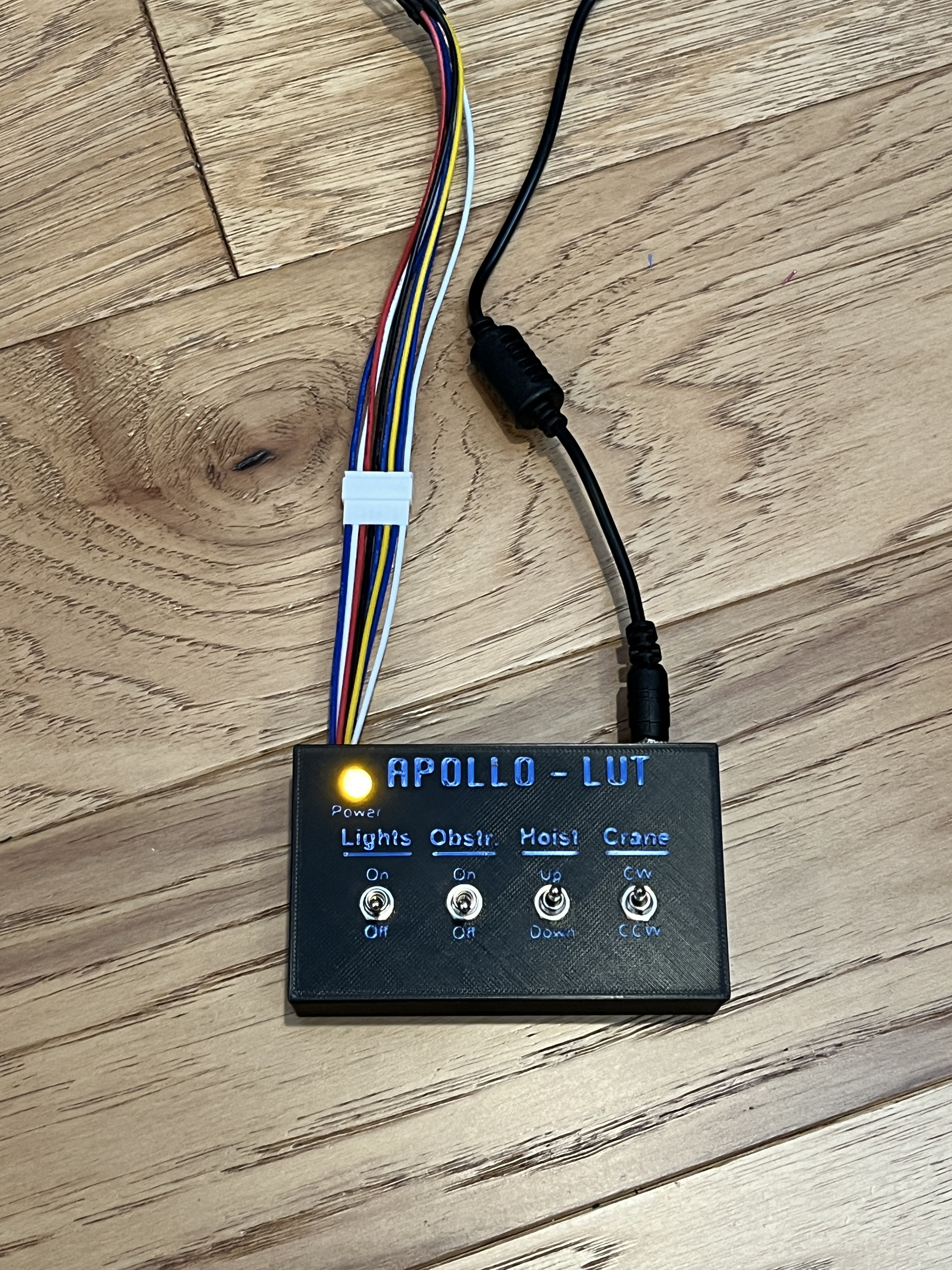
I also created a first cut at a control box. Instead of printing the entire box, I sliced the top off and printed just that with a color change for the lettering.

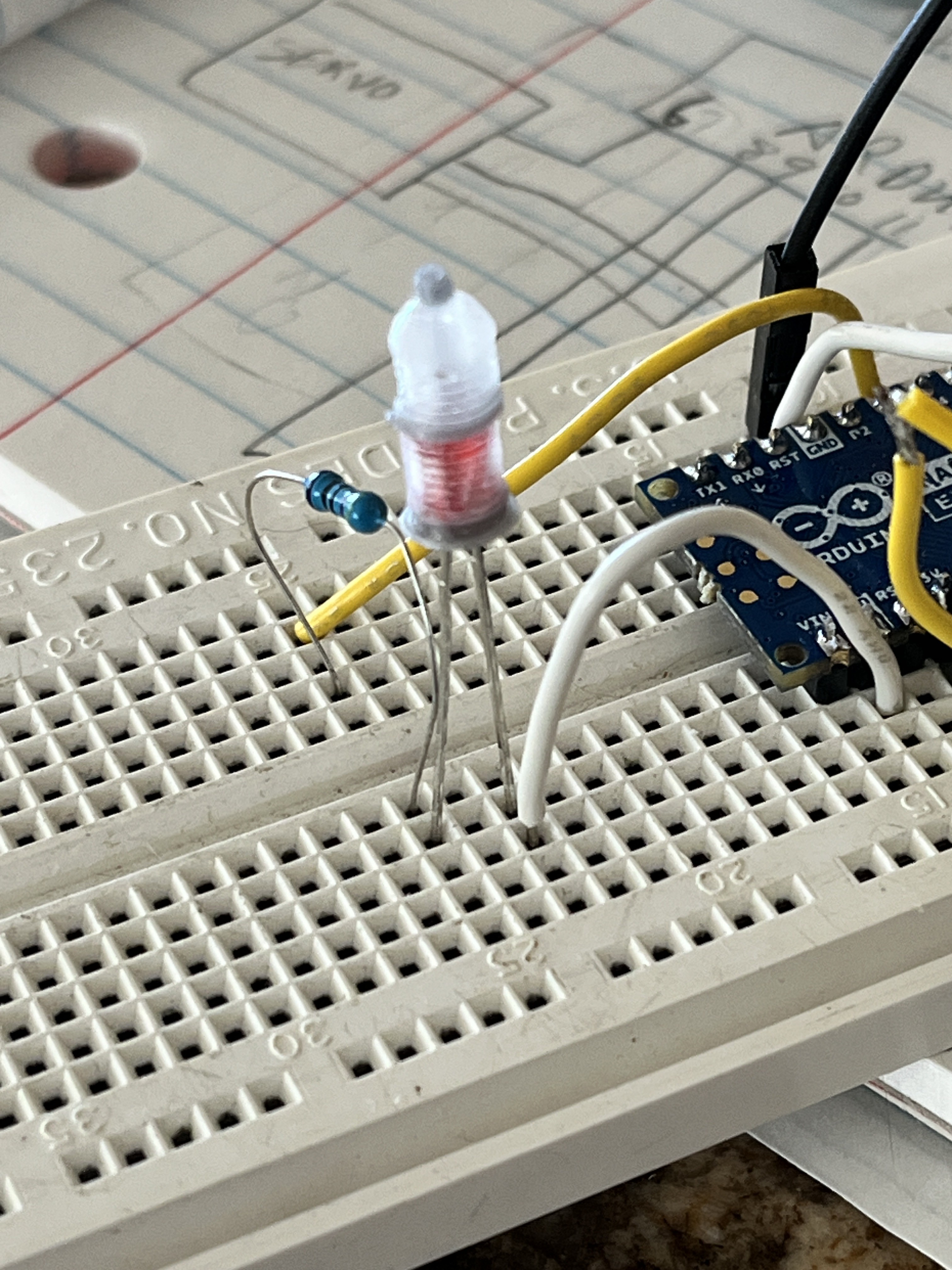
And here is the Arduino code being tested. The one switch turns on/off the blinking LED and the other switch activates the hoist up/down. It is still a work in progress. The hoist does not yet operate smoothly but has a slight pause due the LED blinking.
The components that need to be inside the machinery house are installed. Once I positioned the hoist winch there was just enough room on the side to mount the Arduino. I had hoped to mount the two stepper motor controllers flat but there was not enough room so I glued their mounts to each other back to back and then glued that the floor at an angle so the wires will route better. Everything is still removable and accessible. There are also three small C-clamps that I added to the parts list. These are used to glue the wires to the underside roof of the fixed portion of the house. This keeps the wires routed away from the winch. Now I just need to build a wiring harness to connect the various wires to the arduino and test everything out yet again. I also used an ohm meter to make sure I understood the wire colors from the underside of the launcher into the machinery house.

I have started wiring the control box.
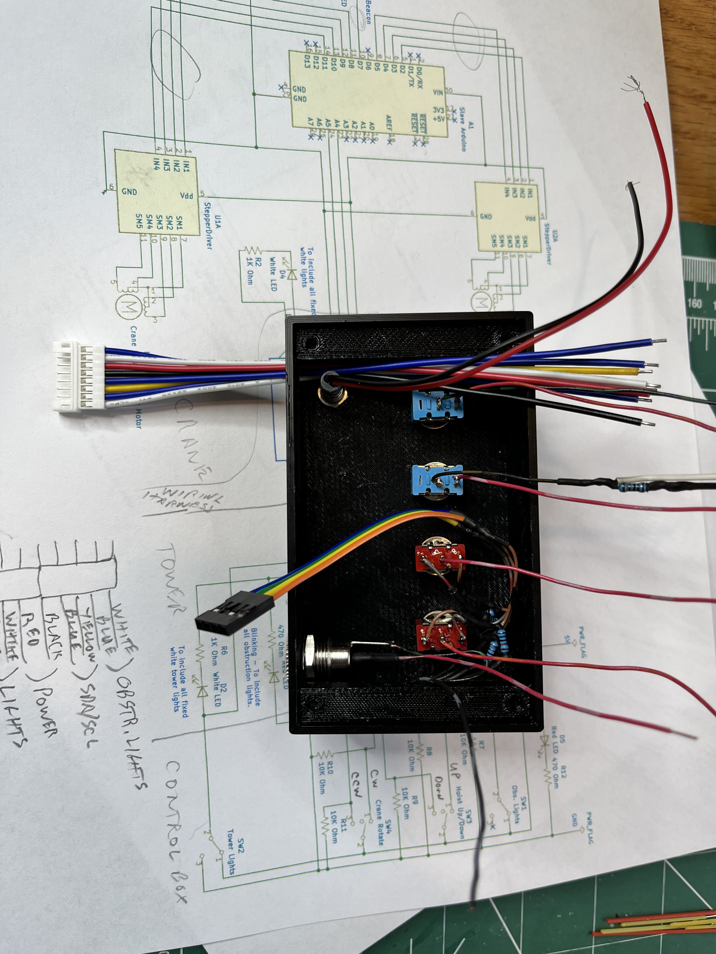
And here is an updated wiring diagram. Not much has changed other than reorganizing and clearly delineating what parts go where as in control box, tower, wiring harness (the wires going up through the elevator shaft) and the crane. I probably could have combined the ground wire for the lights and the obstruction lights but initially it made sense to run pairs of wires. I intentionally separated out the arduino slave power and ground from the lights.
Here is the control box with the wiring complete. I have bench tested it with an ohm meter. Now I will write another program to test the control box, make sure all the I2C commands are being generated. Then I will hook it up to the tower and verify the lights and obstruction lights.


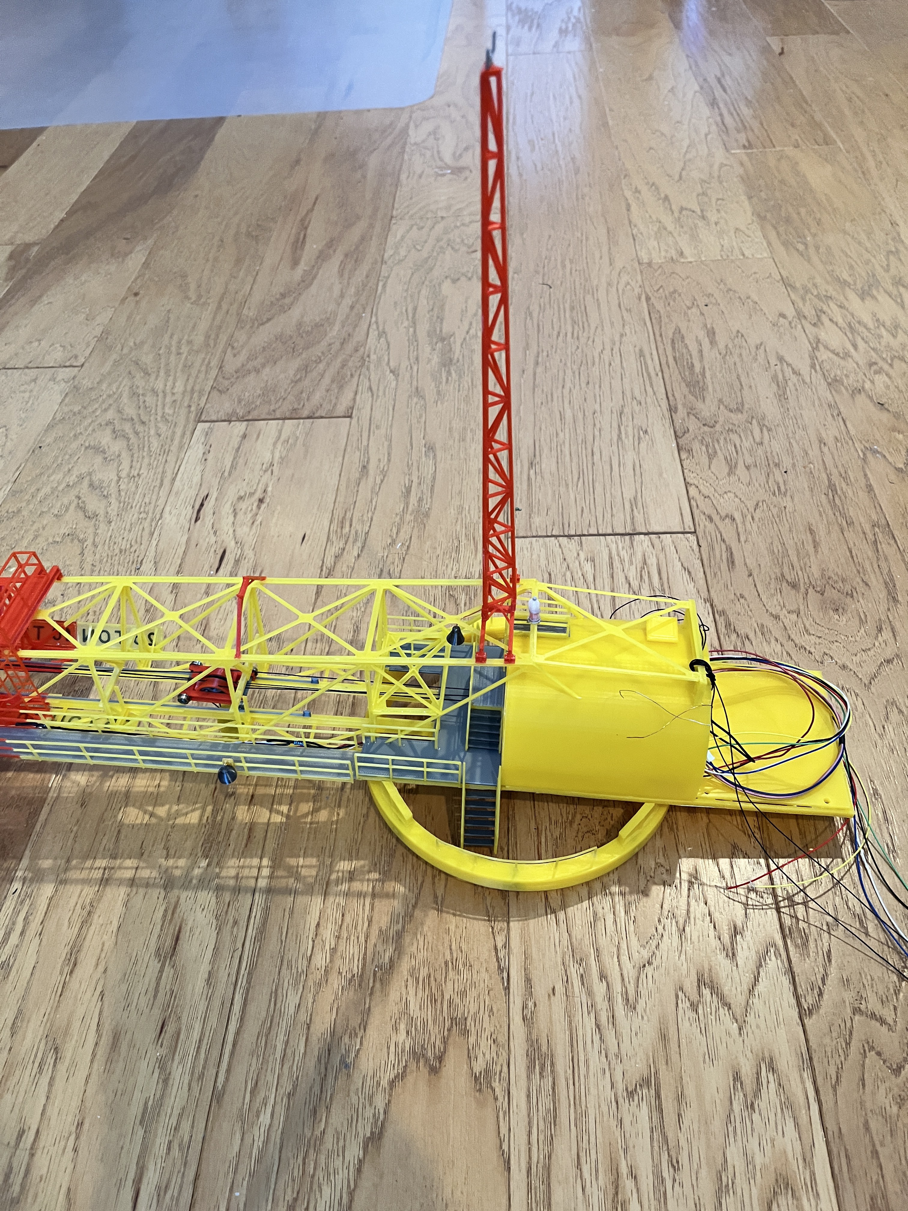
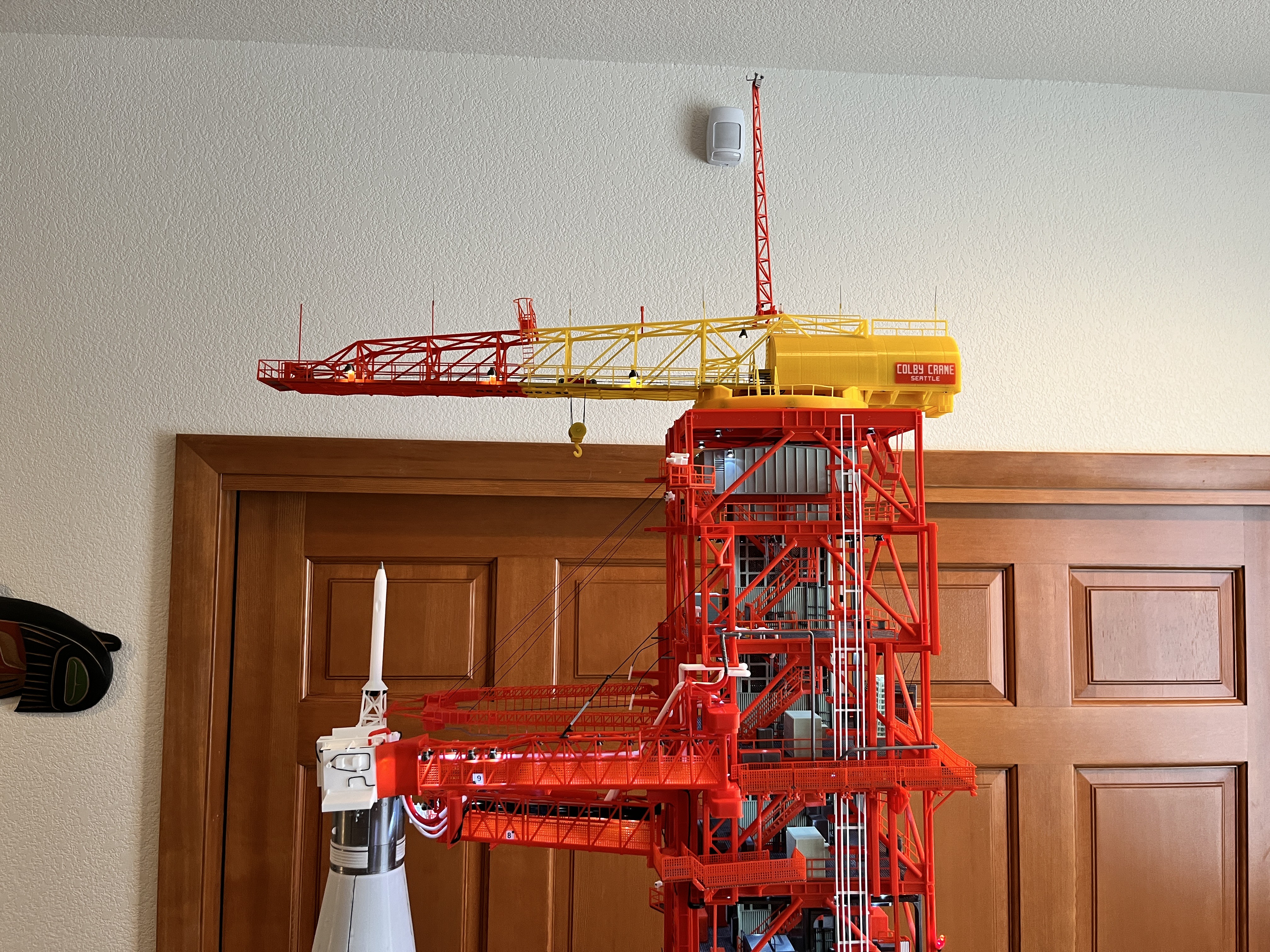
The crane is now complete, on the LUT and functioning. The hoist is slow so I still have some software updates to do but I will publish what I have.
Discussions
Become a Hackaday.io Member
Create an account to leave a comment. Already have an account? Log In.