Why? Fair question… this plotter was the fallout of 2 converging topics. (1) Recently I was debugging a current mirror and was frustrated that there were no IV curves on the BJT’s datasheet, and (2) I’ve been meaning to find an excuse to start automating my lab.
The Humble Current Mirror…
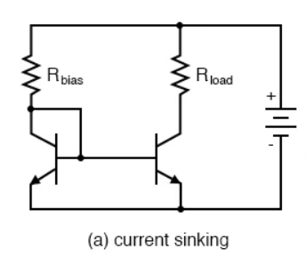
As a reminder the basic current mirror that was drilled into my head through university is shown below. The key idea of this design is that the base-emitter voltage drop is mirrored by both transistors. If the two parts are well matched this should lead to identical base current, and thus similar collector current (Ic = B*Ib). The current across Rload is set by changing the value of Rbias…. Current = (Vcc-0.6)/Rbias.
Current Mirror Woes…
While debugging a circuit at work, I started to think about this design a bit more critically… and came to the realization “WOW the generic current mirror sucks!” Or at least, you NEED to look very closely at the BJT pair you’re using. Let’s go over the common issues with this circuit, hopefully when I inevitably run into another of these in the future, I’ll know the red flags.
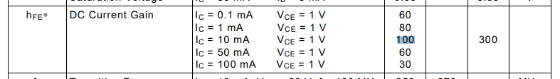
First and most common issue is BJT matching. This issue can be explained by (Ic = B*Ib)… since Vbe should be mirrored, we’ll assume Ib is too. In this case, Ic will be directly proportional to the gain beta. Any error in beta between these two transistors result in an error of our expected collected current. If we look at the datasheet for a jellybean npn BJT we see a wide spec for min/max gain (100/300).
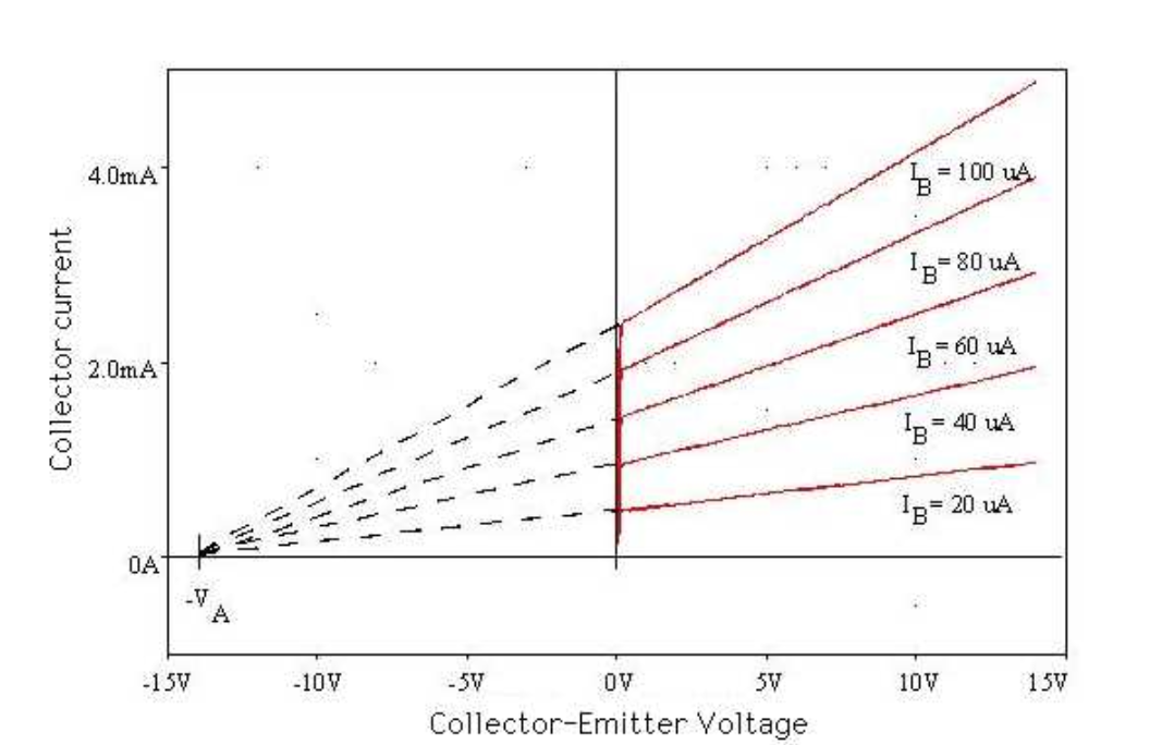
Next issue, the early effect! The early effect shows itself as a gradual increase in collector current as Vce is increased (see below). We previously mentioned our leftmost transistor has its Vce “locked” around 1 diode drop, but the right one is meant to maintain its current regardless of Vce… Clearly, looking at the graph below, collector current is still a function of collector-emitter voltage!!! If we want our current mirror to function well, we want the Early Voltage "Va" to be as large as possible. Otherwise, we’ll see a sizeable error that is dependent on Vce.
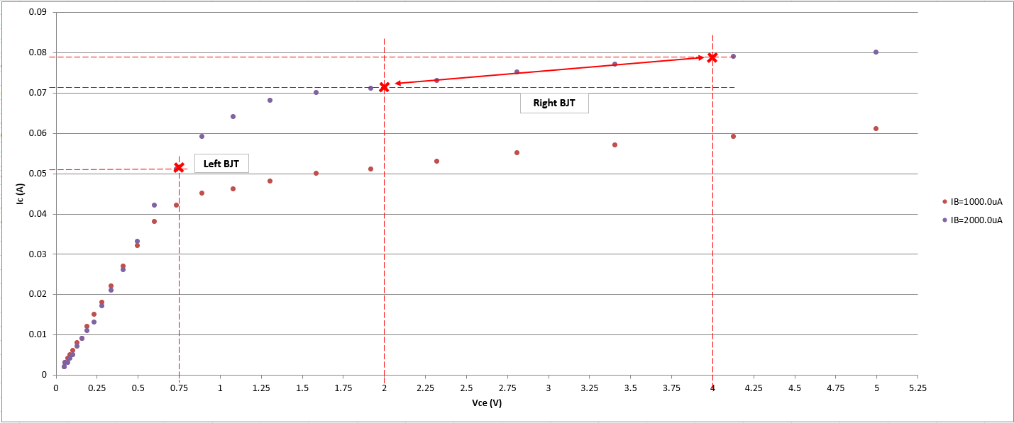
Last issue, is the operating point of the leftmost transistor. We know that Vce will be locked near 0.6V, what happens if the left transistor is in saturation while the right is active? See an example below (taken from Nexperia BCM56DSF)… If I used a BCM56DSF based current mirror set to 50mA, it seems like one part will be operating in the “knee region” (errr saturation) while the other would be comfortably in the active region. We expect the two set points to be along the same Ib “curve” of this BJT characteristic, see below. We can avoid this problem, with our transistor (low saturation voltage) & setpoint.
Note: I couldn't find any mention of this "issue" with current mirrors online, so maybe I'm missing something here... take my last gripe with a pinch of salt
TLDR - Don't use a half baked Current Mirror in your circuit.
- Gain Errors, Early Effect, Ensure both BJT's in active region
Discussions
Become a Hackaday.io Member
Create an account to leave a comment. Already have an account? Log In.