In this blog post, we’re going to draw the circuit schematic of 61-key variant of Carpenter Tau keyboard. we will take into consideration that the microcontroller circuit can also be applied to the 87-key and 104-key models, ensuring that we allocate enough GPIO ports and maintain the circuit’s reusability.
Before we start
To begin with, it is essential to select a reliable EDA software that allows us to create accurate circuit schematics. My favorite option is KiCAD, which stands out for its open-source nature, impressive capabilities, and user-friendly interface. However, when it comes to finding all the necessary footprints and managing BOM assignments, it can sometimes pose a challenge.
In such cases, an alternative worth considering is EasyEDA, a free software developed by JLCPCB, a renowned PCB manufacturer and electronic components distributor. One of the notable advantages of EasyEDA is the availability of real-world electronic parts, complete with their respective prices and stock information. This invaluable feature allows us to plan and produce the projects more effectively. In this particular project, there’s no symbol library and footprint for the CH582 maincontroller but it’s right available in EasyEDA.
Now, when choosing between EasyEDA Pro and EasyEDA STD, it’s important to note that despite the “Pro” label, EasyEDA Pro remains a free software. The key difference lies in the underlying technology. EasyEDA Pro utilizes WebGL, a powerful graphics rendering technology, which ensures scalability even when dealing with complex schematics and PCB designs. On the other hand, EasyEDA STD is based on SVG, which may have limitations when handling a large number of elements. Therefore we’ll going to use EasyEDA pro for this project.
Draw the keyboard core circuit
First we draw the microcontroller part, the minuimum system, the USBC, power supply and the battery charging.
The CH582M SoC minimum system
We can find a CH582M datasheet and reference minimum system schematic from their official github:
We want the on-chip DC to DC feature to reduce battery consumption. So we can mostly copy this minimum system schematic, and let’s also have the boot key and reset key to help download and debug our program.
In order to optimize battery consumption, we aim to incorporate the on-chip DC to DC feature. By implementing this feature, we can significantly reduce power usage. To achieve this, we can leverage the minimum system schematic as reference because it by default includes the DC to DC circuit. Additionally, it would be beneficial to include dedicated boot and reset keys in the design. These keys will help the program downloading and debugging processes during our development.

USB Type C
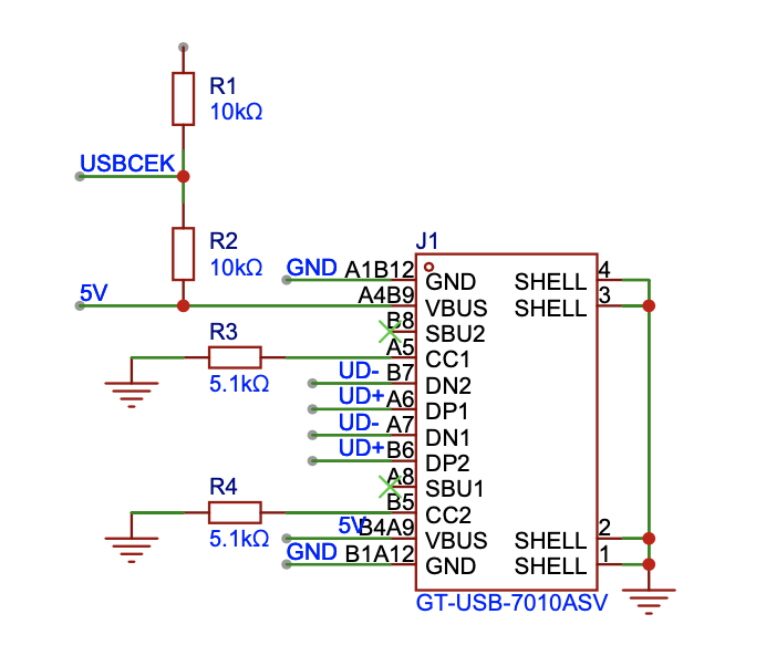
Now, let’s delve into the USB Type C component. As the keyboard functions as a Human Interface Device (HID), the need for USB 3.0 is unnecessary. Hence, we opt for a 12-pin (equivalent to 16-pin) Type C interface. Additionally, we leave SBU1/SBU2 unconnected. In our firmware program, it is crucial to detect when the USB Type C is connected. This is because the keyboard can be powered either by USB Type C or the battery. To address this, we establish a connection between the CC pin and one of the GPIO ports, which we label as USBCEK:

The power and charging
Let’s list the basic requirements of power and battery charging for your keyboard. Our desired behavior is as follows:
- When the user connects the keyboard using a USB Type-C cable, it should automatically power on.
- When the keyboard is not connected via USB Type-C, the user should have the option to turn it on for wireless use or turn it off to conserve battery power.
Based on these requirements, we can draw the power and charging setup in the following way:

The battery charging sub circuit remains constantly connected to the USB Type C port. As a result, the charging process is always active whenever the device is connected to a power source, regardless of the switch position. The purpose of the switch is to control whether the battery functions as the power supply or not. When turning off the switch, battery is disconnected and the keyboard will power off if it’s not wired.
Also CH582M requires a stable power output of 3.3V. We utilize the ME6211 LDO, which can convert either a 5V USB power source or a 3.5-4.2V lithium-ion battery power source to the required 3.3V power.
Draw the keys, backlight and tri-mode switcher
Now that we have successfully implemented a standard system that powers up the CH582M chip and supports USB Type C connectivity, including battery charging, let’s shift our focus to the crucial aspect of the keyboard - the keys themselves.
The keys
Every individual key on the keyboard functions as a switch, effectively connecting two GPIO ports. One port signifies a specific row, while the other represents a column. When a key is pressed, the corresponding column GPIO becomes linked to the respective row, allowing our firmware program to detect this signal. Additionally, we have incorporated a switching diode for each key, which serves to prevent any potential ghosting issues.

The backlight
In Carpenter Tau Keyboard it’s a wooden keyboard, which doesn’t play well with a shining RGB backlight. But we do want a plain white backlight to help pinpoint keys at night. We use a single PWM port, a MOSFET circuit to control the brightness of all keys.
The Carpenter Tau Keyboard uses a unique wooden design that doesn’t look compatible with a vibrant RGB backlight. But we do want to feature a practical plain white backlight that comes in handy during nighttime usage. To ensure optimal brightness control, the keyboard utilizes a single PWM port and a MOSFET circuit to adjust the brightness of all LED lights at once:

Tri-mode switcher
Finally we want a way to switch among wired, bluetooth and 2.4GHz connection. While a wired connection can be automatically detected through a USB Type-C cable, we also want to offer the flexibility of charging while using Bluetooth to connect to a mobile device.
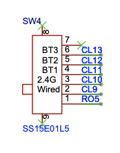
Unlike some keyboards that rely on keyboard shortcuts and firmware detection these shortcuts for connection mode switching, we will opt for a distinctive approach. Because we want to minimize the symbols engraved on the wooden keycap for simplicity, as well as the constraint of limited space for indicating connection mode switch keystrokes on the keycap. Furthermore, we aim to empower users full programmability of keyboard shortcuts so don’t want certain keystrokes are occupied by switching modes. To achieve this, we will use a sliding switch to switch among connection modes: wired, 2.4GHz, and three distinct Bluetooth devices.

Final clean up and summary
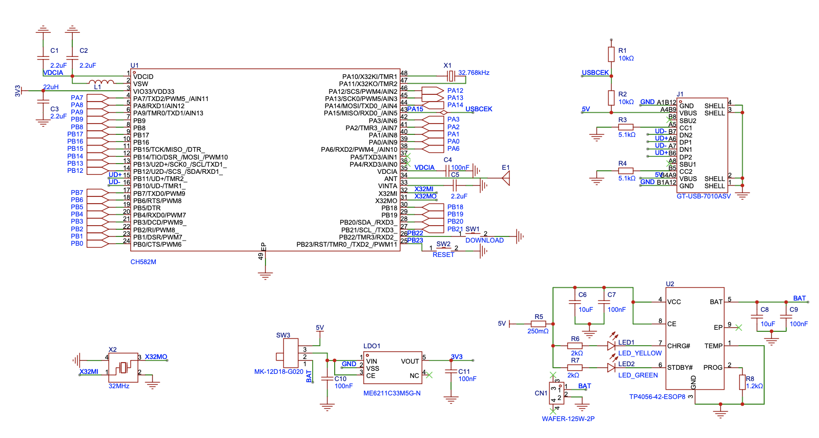
Now we’ve finished all parts of the 61 key Carpenter Tau Keyboard. In next post we’ll build quite similar 87 key and 104 key circuit and the 2.4GHz dongle circuit. So we are moving the common parts of the keyboard controller to a resuable module and name it as KeyboardCore. Only keep the 61 keys, 61 backlight LEDs and tri-mode switcher to the 61 key schematic file. The final layout looks like this:
We have successfully completed the assembly of all components for the 61-key Carpenter Tau Keyboard. In our upcoming post, we will be constructing circuits for the 87-key and 104-key variants, as well as the 2.4GHz dongle circuit. Because 87-key and 104-key will be quite similar in the schematic, we move the keyboard controller part of circuit into a reusable module, named KeyboardCore. The resulting layout is depicted below:


You can also find the result source code of the schematic in our github: https://github.com/taukeyboard/carpenter-tau-keyboard.
 Bo Yao
Discussions
Become a Hackaday.io Member
Create an account to leave a comment. Already have an account? Log In.