 mircemk
Light Emitting Diode as an electronic component are very often used in electronic devices. There are many different types with specific characteristics such as forward voltage and maximum current. Most often it is necessary to connect them to a higher voltage where it is necessary to connect a series resistor with a certain value.
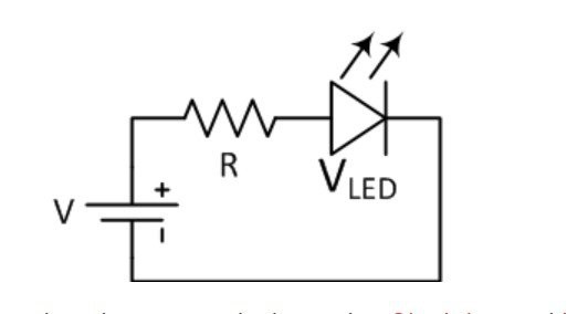
The device described in this video is a useful tool for testing, and determining characteristics of LEDs, as well as a calculator for calculating the series resistor depending on the connected voltage.
The idea for this project was taken from Dave Cook's model, processed with an Arduino from Jaycar Electronics, and I made some changes to the code where uses an I2C LCD display, and dedicated buttons to control the device, instead of an LCD keypad shield.
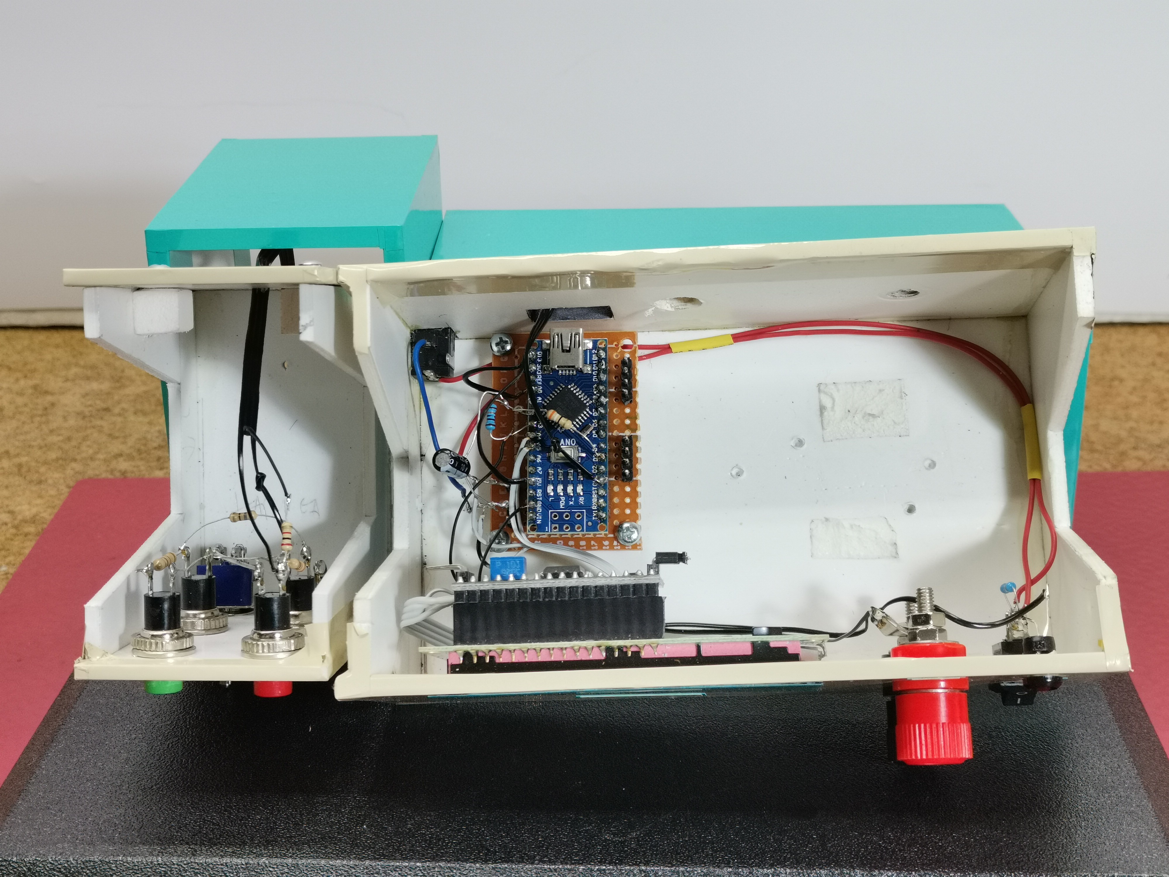
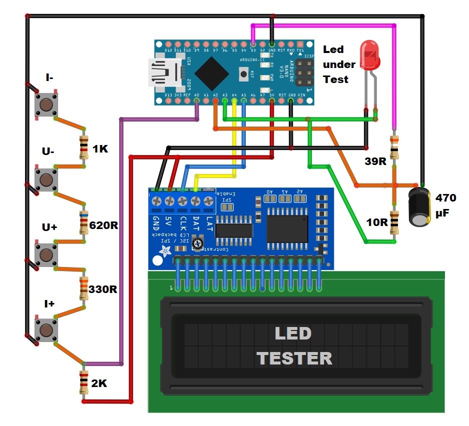
The device is very simple to build, and consists of several components:
- Arduino Nano microlontroller
- 16x2 LCD Display with I2C communication protocol
- 7 Resistors
- capacitor
- and four Buttons
If you want to make a PCB for this project, or for any other electronic project, PCBway is a great choice for you. PCBway is one of the most experienced PCB manufacturing company in China in field of PCB prototype and fabrication. They provide completed PCB assembly service with worldwide free shipping , and ISO9001 quality control system. Also, on their site there is an online gerber viewer where you can upload your gerber and drill files to render your board.

And now let's see how the tester works in real conditions. When turning on the display appear previously defined values for the current and voltage to which the LED would be connected, namely a current of 10mA and a voltage of 14V. With no LED attached, it will not show a resistor value, and current value blinking.
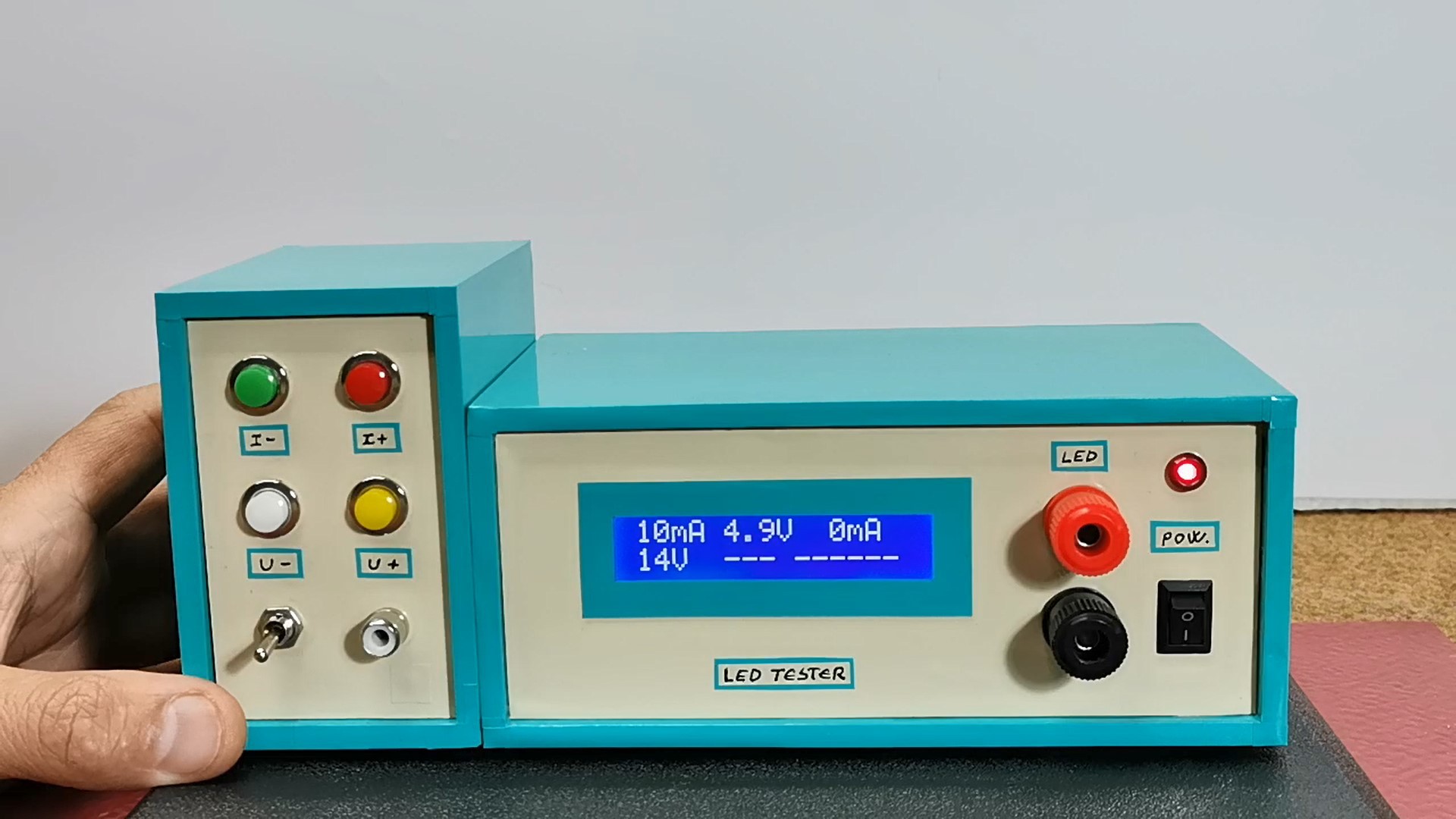
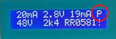
The upper buttons can be used to set the current that will flow through the LED in the range from 1 to 20mA. These are values that in most cases cannot cause damage to the LED. The lower buttons set the value of the voltage to which the diode would be connected through a series resistor in the real circuit. This voltage can be set from 1 to 99 V, and the display then shows the required resistor value depending on the selected voltage and current. Also on the lower right part of the display appears the code of that resistor under which we can buy it in Jaycar Electronic shop. If the resistor would dissipate more than half a watt, a P flashes on the top line to let you know you might need to choose a more powerful resistor. If by mistake we connect the diode with reverse polarity, the diode remains functional, it just won't light up.
And finally a short conclusion. The device presented in this project is very simple to build, but it is a really useful instrument in the laboratory, especially due to the fact that many different types of LEDs are used nowadays. The device is embedded in a suitable box made of PVC material and lined with self-adhesive colored wallpaper

 Sagar 001
 Ben Holmes
Only one led can be tested individually