 Andrew Kotite
Overview
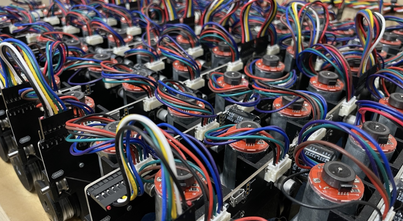
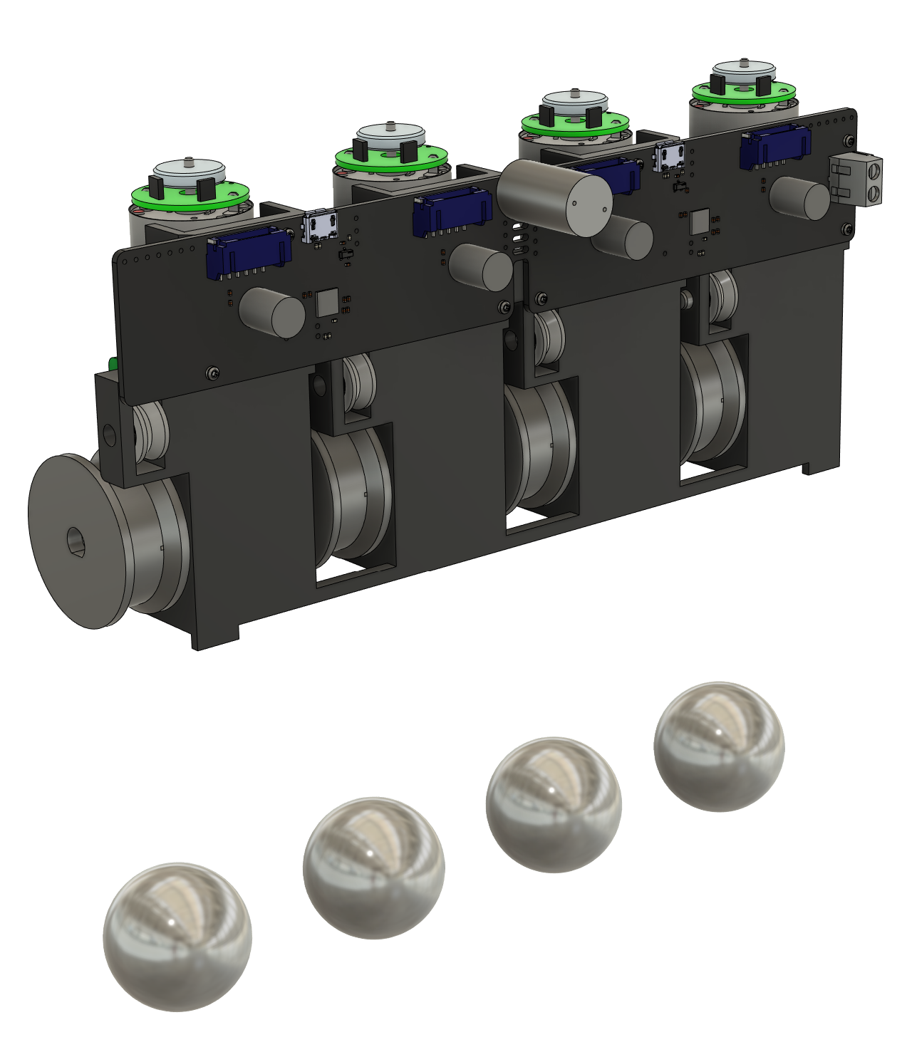
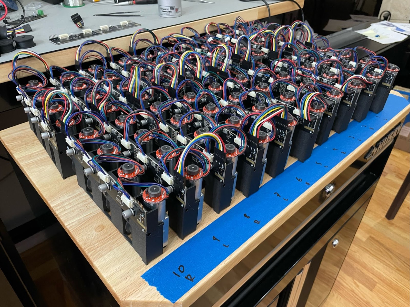
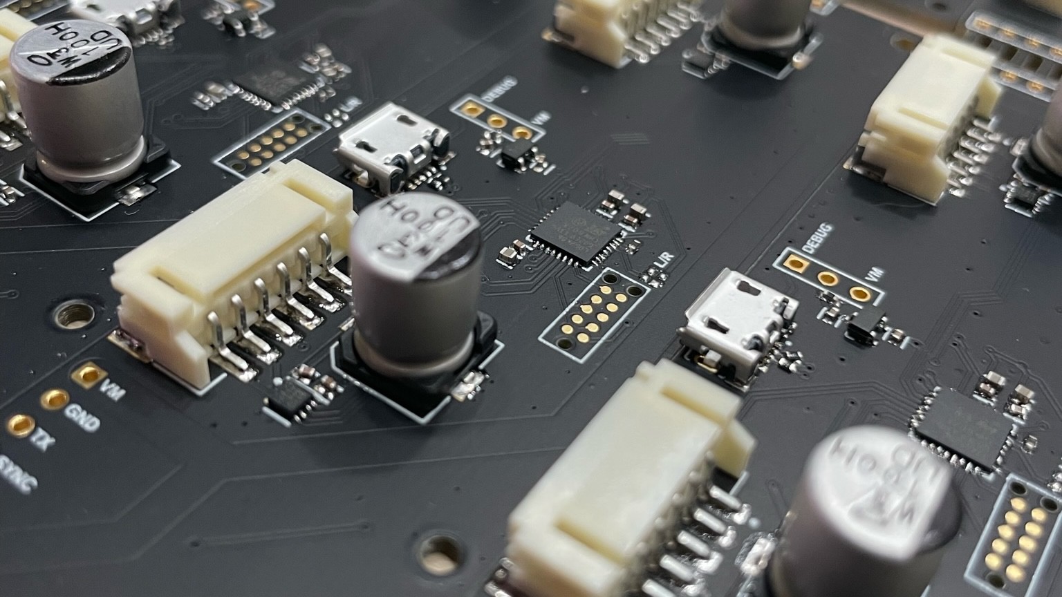
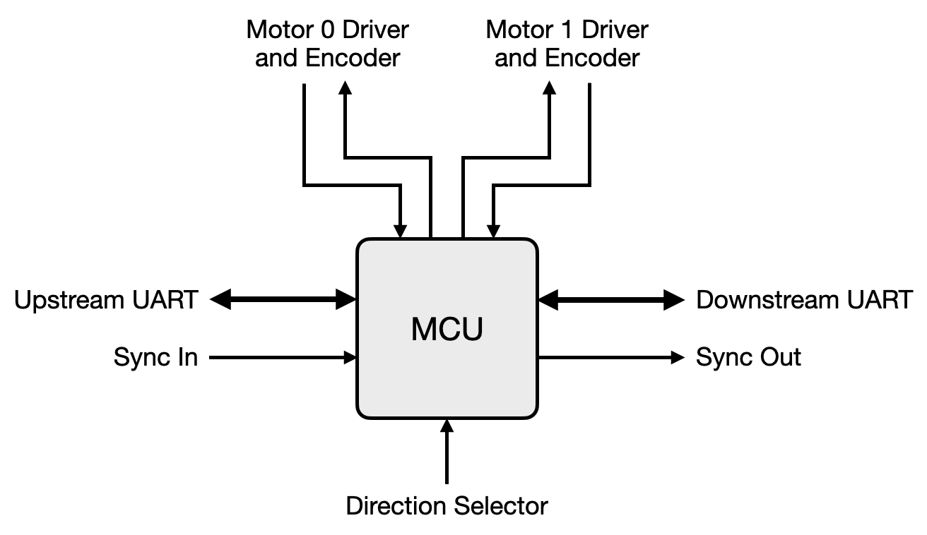
Internally, the sculpture is organized into modules of four motors. Every module has a circuit board with the motor drivers, power regulators, comms interfaces, and two microcontrollers. Each microcontroller is responsible for the position control of two motors.
The modules are chained together through 7-pin connectors that carry power and communications, zig-zagging back and forth to form the ten rows of the sculpture:
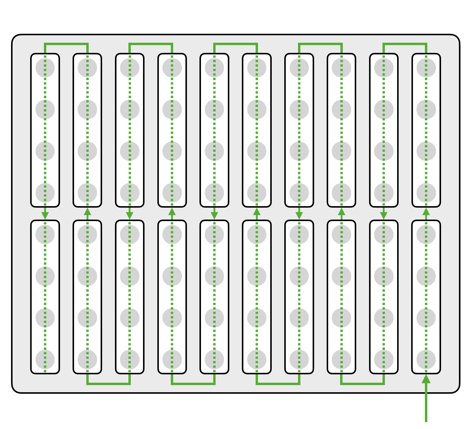
A Raspberry Pi connects to the first module in the chain (at the lower right corner, above) and handles the overall control and coordination of the sculpture, from animation to homing to firmware updates. It also drives the lights directly.
The modules are powered by five 6-volt power supplies (one per two rows), while the Raspberry Pi and lights are powered by a single 5-volt supply.
Mechanical
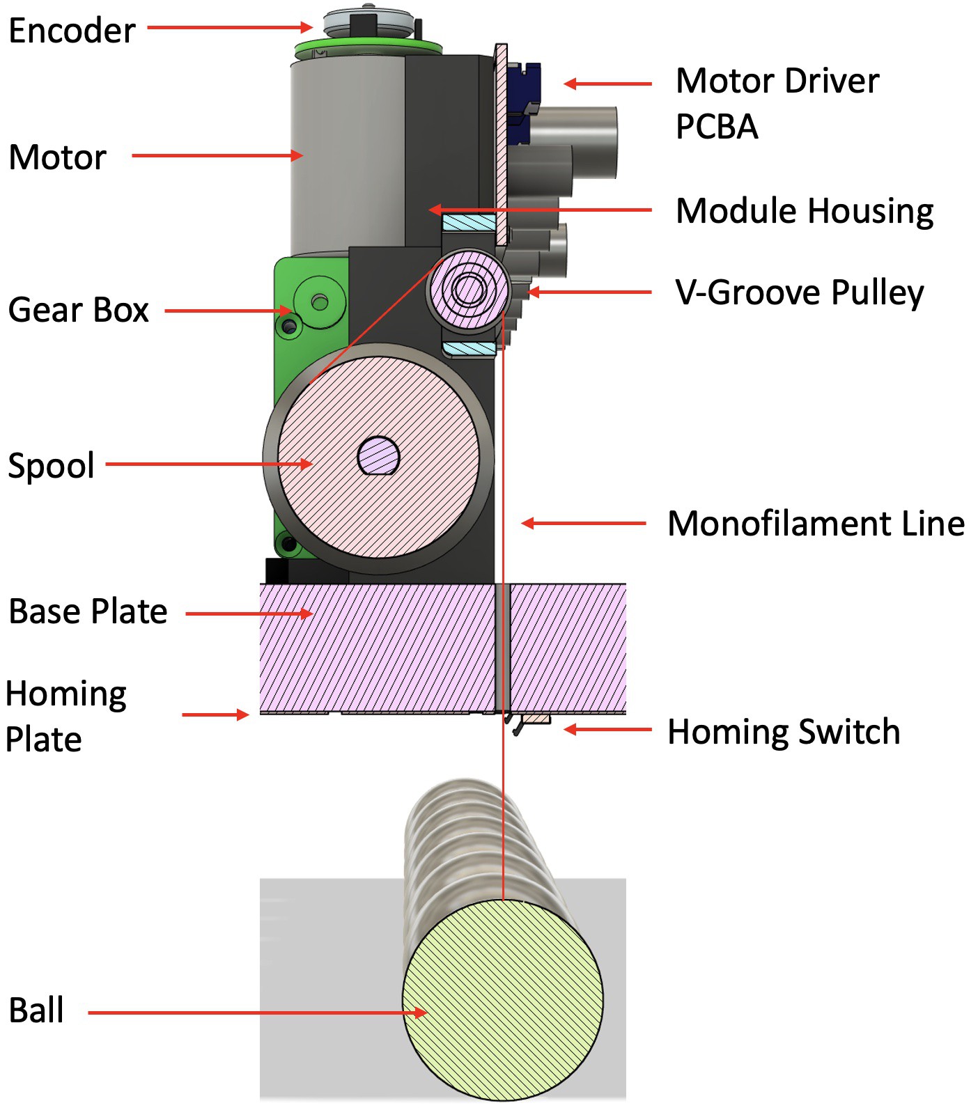
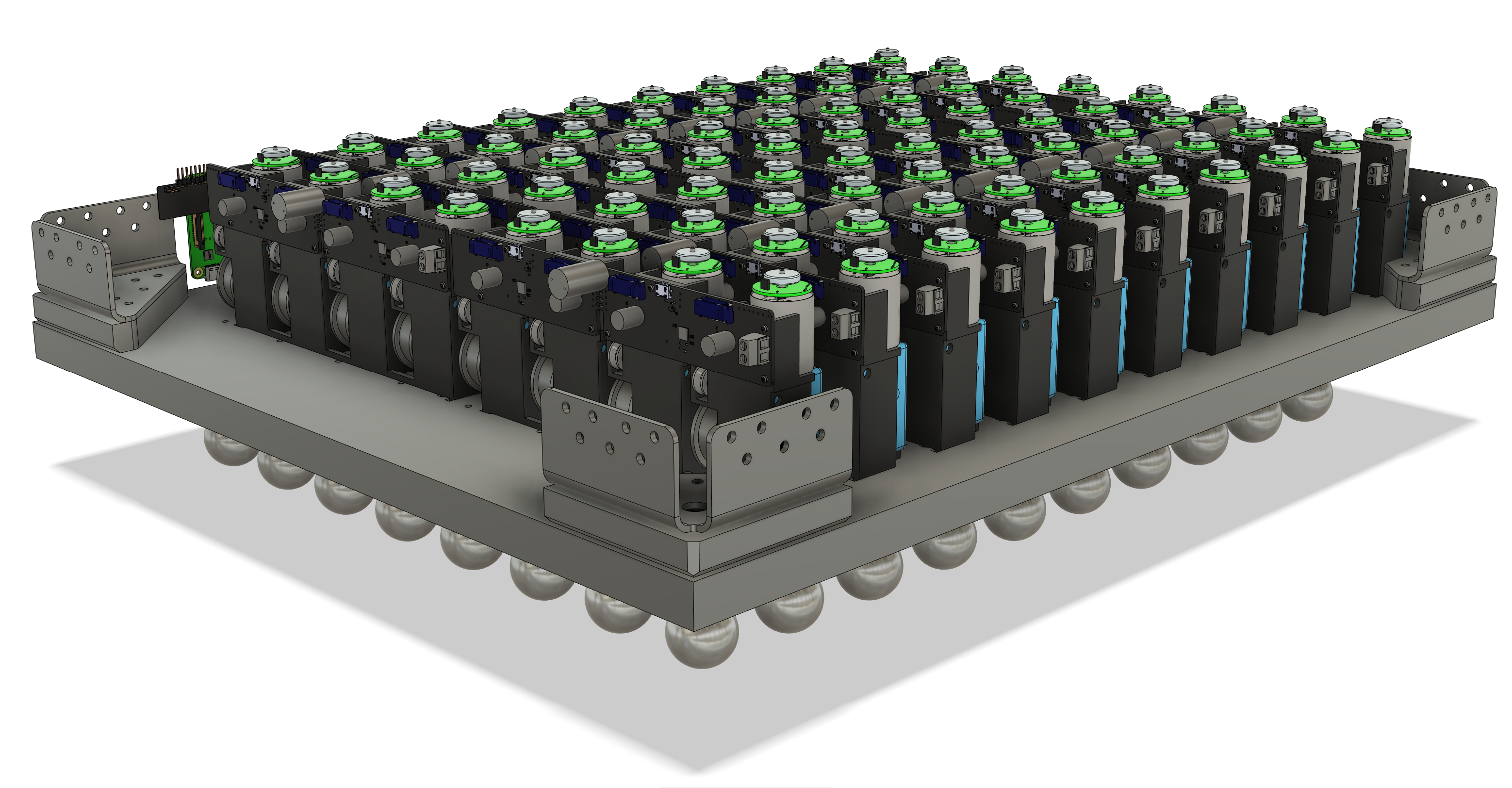 The module housing is designed to be 3D printed, and it provides mounting features for the motors, pulleys, and circuit board, as well as features to locate and mount the modules in the enclosure. In an effort to reduce part count and make assembly simpler, many components are held captive in the housing by other components. For instance, the pulley axle is held in place by the housings of the motor gearboxes on either side.
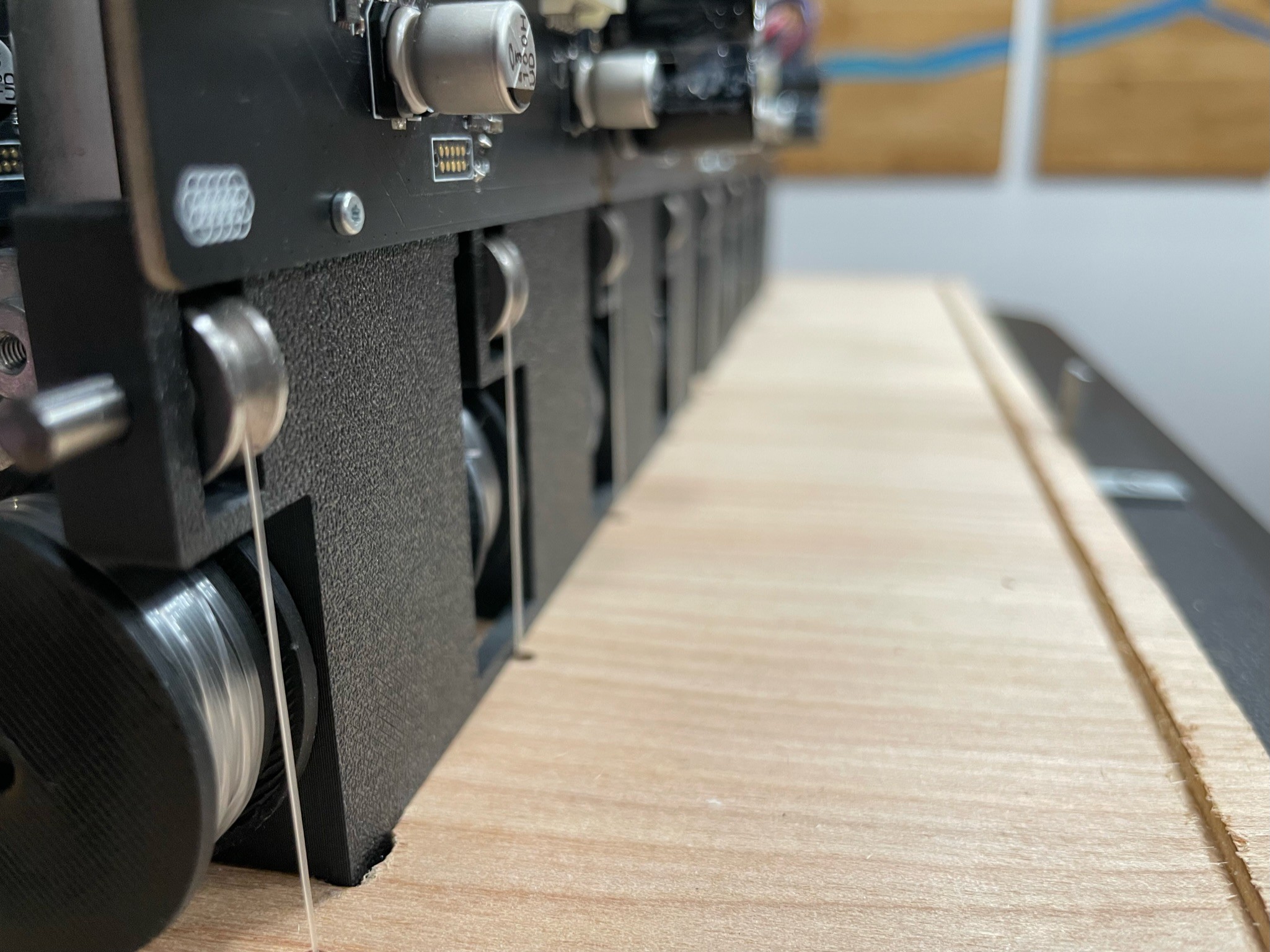
The cables that hold the balls are routed such that the weight of each ball provides a sideways load through the motor gearboxes into the housing, which eliminates the need for glue or retention screws to mount the motors. A light friction fit suffices to keep the modules in place.
Base Plate
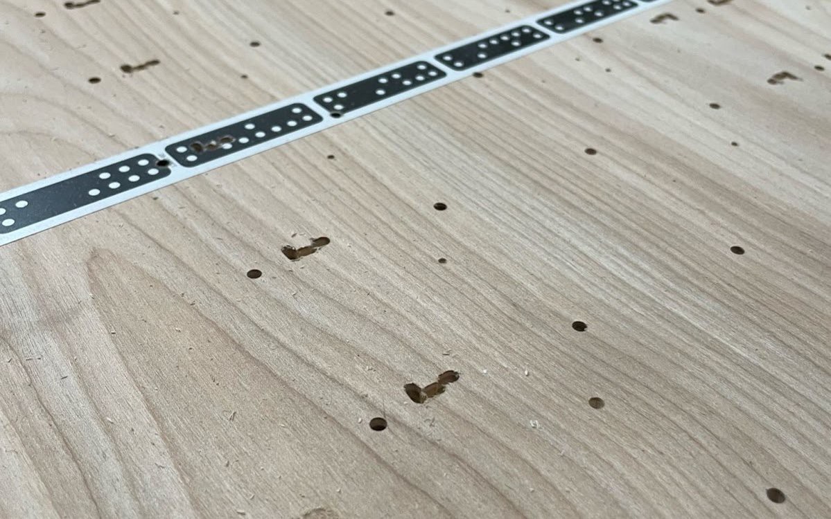
The placement of the modules relative to each other and to the rest of the enclosure relies on features CNC milled into the base plate (the bottom of the enclosure). We used a Shaper Origin to cut out alignment slots for the modules and drill holes for the ball cables to pass through (and later to cut channels used for the homing plate interconnect boards, more on those later).
![]() Motors
Motors
 Motors
There were many things to consider when selecting a motor: how fast we wanted the balls to move, the position resolution we could get, noise, power, and, of course, cost.
It quickly became clear that brushless and stepper motors would be prohibitively expensive for the first version of this project, so while there are drawbacks to DC motors, we ultimately found a supplier of semi-custom motors that we were happy with. They include a 48-count magnetic rotary encoder, a 143:1 gearbox with a worm gear, and a connector, all for $6 each. Having all that integrated into one unit also greatly simplified the mechanical design. The worm gear is important, as it prevents the balls from falling and crashing when power is lost.

Balls
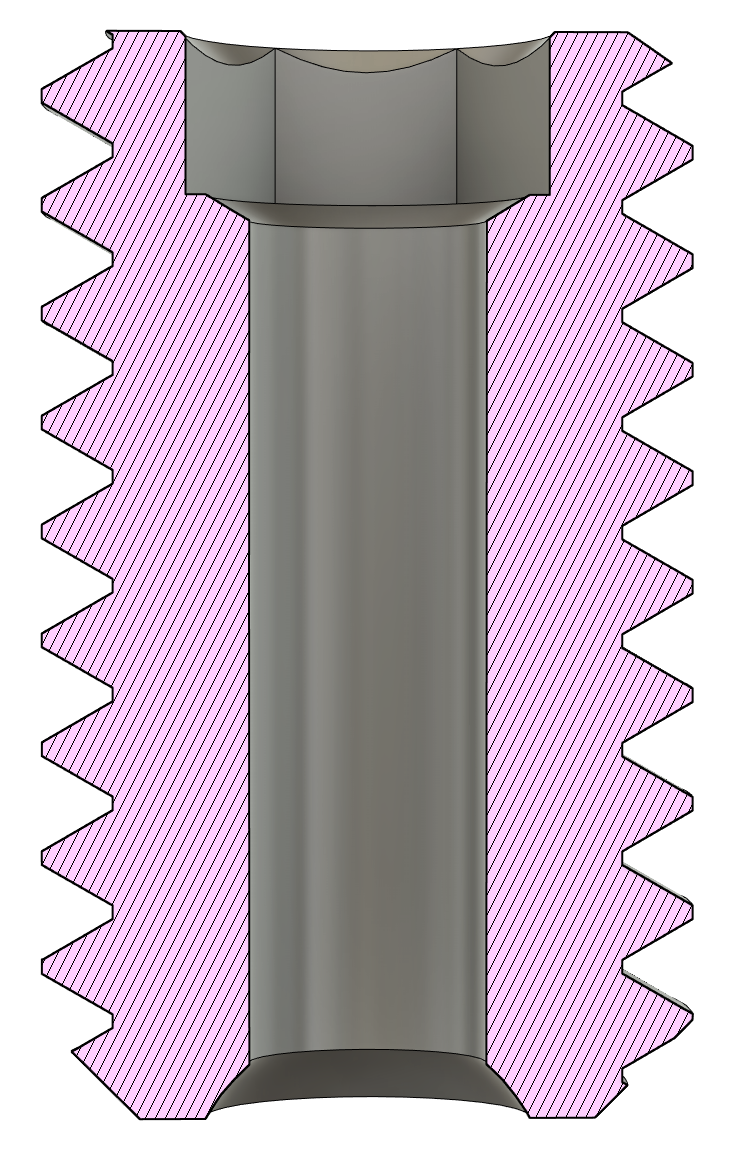
Once we figured out the ball size and spacing, we started to think about how to attach a cable to a solid steel ball. All of the solutions we considered involved drilling a hole into the balls, which would be a big challenge without specialized equipment. Luckily, we were able to find a supplier that could machine the balls for us, drilling and tapping a 10mm M3-threaded hole in each one. To attach a cable to a ball, it's passed through a vented set screw and knotted off, then the set screw is screwed into the threaded hole.
Homing Plates
The encoders on the motors give us great incremental position sensing, but we needed a way to accurately zero the balls to a known reference point. To do this, we made four homing plates, which are circuit boards with micro switches above each ball. During the homing process, a ball gets its zero position from hitting its switch. We also took the opportunity to add 172 addressable RGB LEDs to these boards to give the sculpture its own lighting.
In the photo below, you can see the homing plates, LEDs, switches, and the 3D printed ball guides around each hole. These guides protect the switches from strain, and they stop any side-to-side movement of the ball if it's swinging as it comes up to the switch.

Mounting Brackets
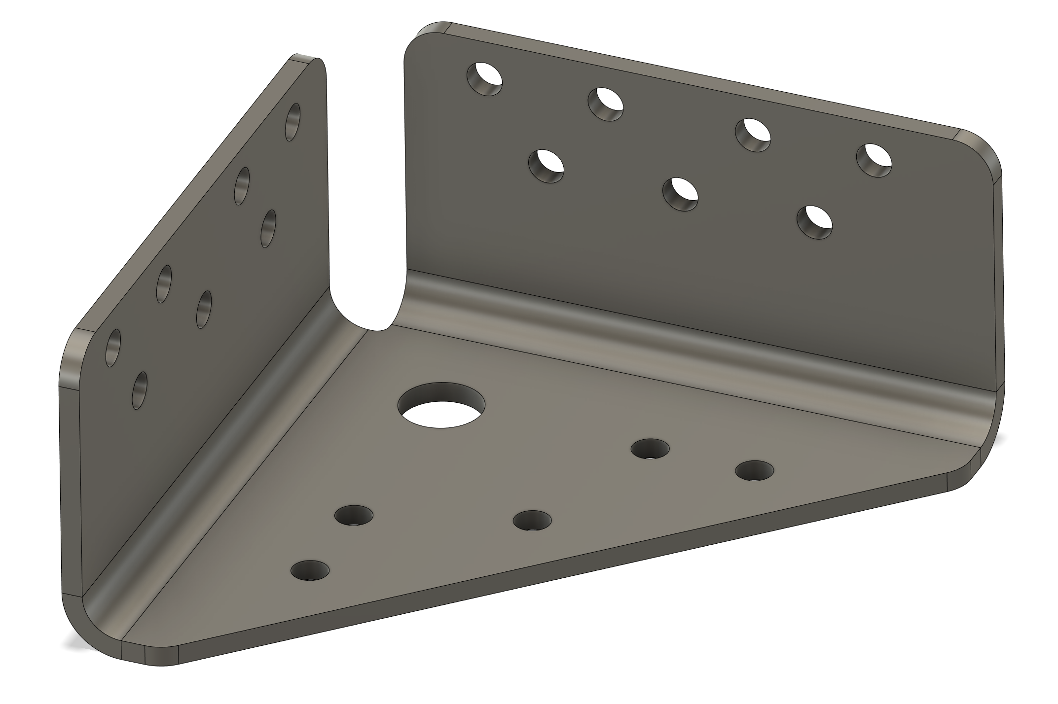
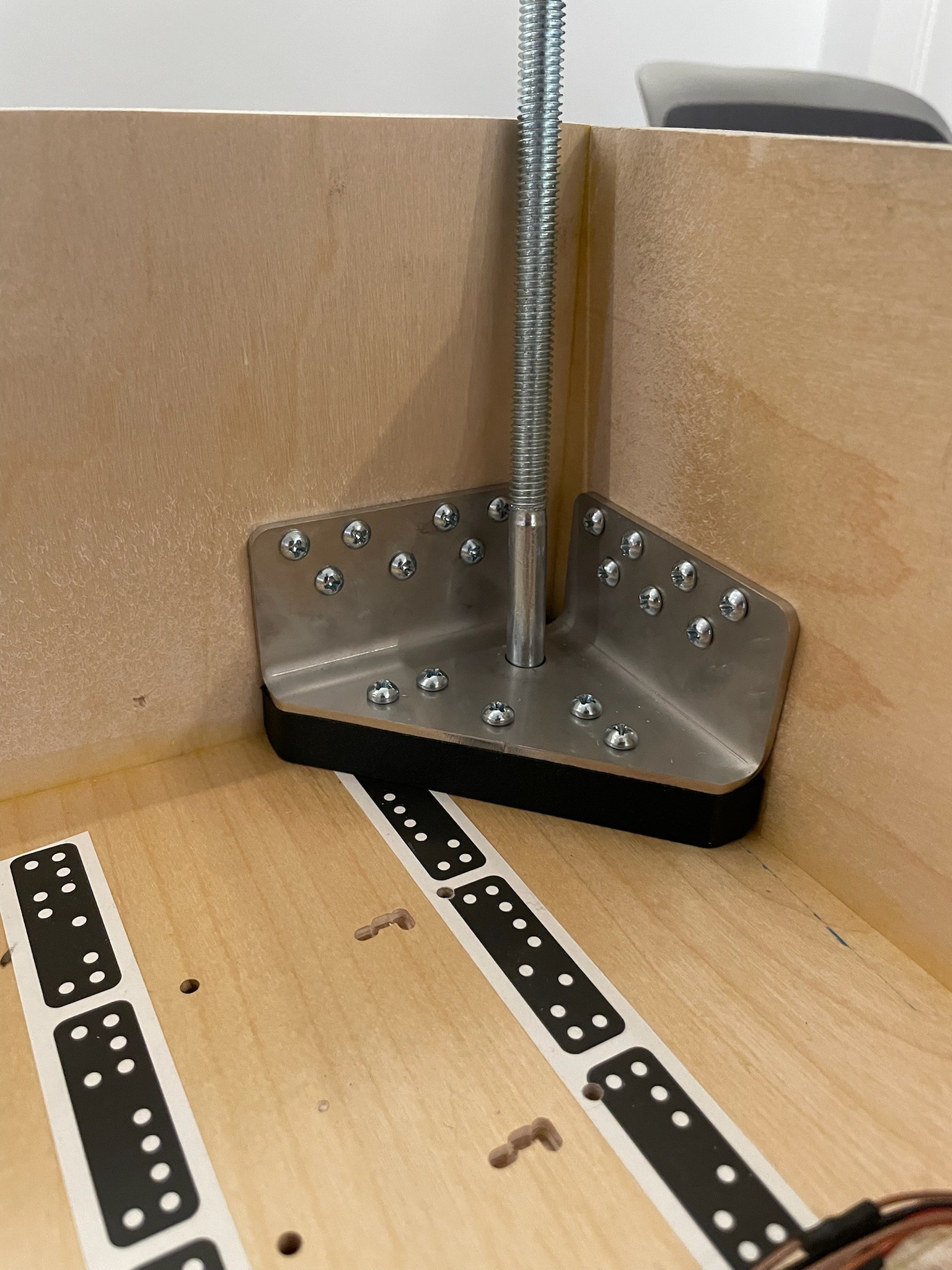
With 80 steel balls and 80 motors with 80 gearboxes, the whole sculpture weighs over 150 pounds. We couldn't find any off-the-shelf brackets that we trusted to hold the weight, so we designed some custom brackets that could be laser cut and bent into shape. We carefully considered the number of screws needed to attach the brackets to the enclosure, ultimately landing on "as many as we can fit".
Electrical
The custom circuit boards on the modules each have two STM32L062K microcontrollers, with each one controlling two DRV8837 motor drivers for a total of four motors. The part selection was largely driven by what we had on hand, which in some ways wasn't always optimal, but it did help a good bit with cost.
The board is designed to be split in half in case a particular sculpture configuration has a row size that isn't a multiple of four balls. To accommodate that, each side of the board also has its own LDO to power the microcontroller.
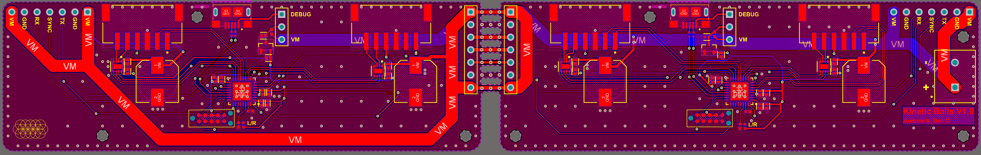
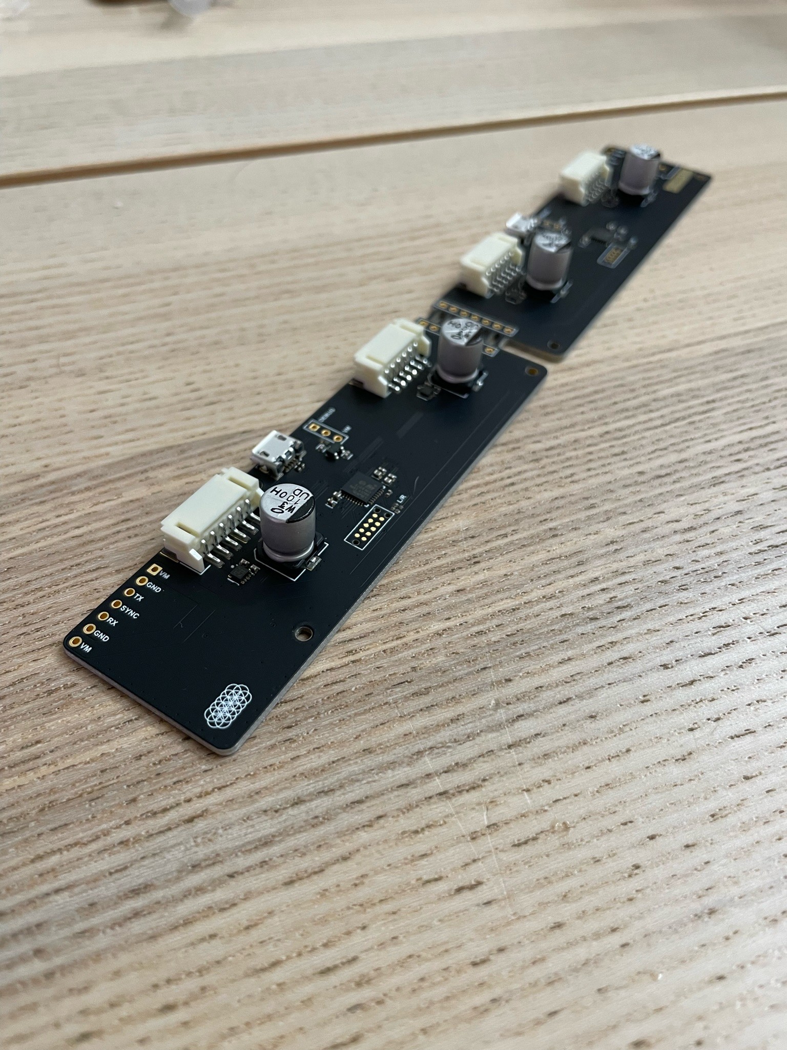
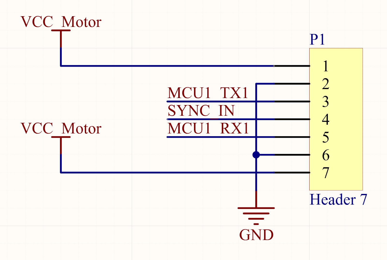
Module Connector
The modules connect to each other through a 7-pin connector. The pinout of the connector is symmetrical, which is helpful in a couple ways. First, it means that accidentally flipping the connector 180 degrees won't short ground and power. Second, it makes it trivial to swap the UART pins between modules, which is needed when going from the end of one row to the beginning of the next in the zig-zag.
![]() Power
Power
 Power
PowerWhen they're running at full speed, each motor only draws about 200mA of current at 6V. However, the inrush current when they first turn on can be over 1.5A per motor. After some testing with the full array, we found that the power supplies couldn't handle the inrush current without some help, so we added over 4400uF of extra capacitance to each module. We had originally planned to use two or three 60W power supplies, but ended up with five of them, one for every two rows.
Pi Hat and Homing Plate Interface Boards
We designed a couple more circuit boards to minimize the wiring harnesses needed in the enclosure. The first is a Pi Hat that connects the Raspberry Pi to the modules, homing plates, and power. To route the homing plate signals across the enclosure to the Raspberry Pi, we used two very thin and long boards (400mm) that rest in channels cut into the base plate.


Firmware
The microcontrollers that drive the motors are STM32L062s, which were chosen mostly because we had them on hand, though they ended up being a little underpowered for this application (more on that later). The firmware itself is a simple bare-metal C application with minimal dependencies, just using cooperative multitasking in a top-level loop.
The microcontrollers use two UART interfaces to communicate, one going upstream toward the Raspberry Pi and one going downstream to the rest of the chain. The motor encoders are quadrature encoded using two GPIOs, and the motor drivers also use two GPIOs each to set the drive mode. Besides that, there are the sync in and out GPIOs for animation timing, a TagConnect footprint for SWD, and a USB port that exposes an emulated serial device to print logs over.
Lastly, there's a solder bridge on the circuit board to select whether it's a left- or right-facing module. Because the modules are chained in a zig-zag, every other row needs to switch direction, so the microcontroller reads the solder bridge and swaps the UARTs and sync pins accordingly.
Communications
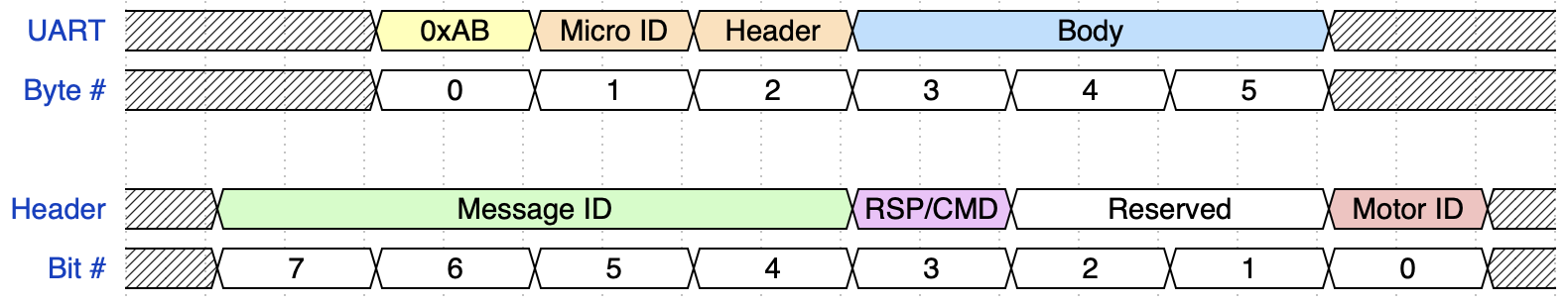
During normal operation, the UART interfaces run at 230400 kbps, using a simple packet format to move messages around. The first three bytes of every packet have a fixed format:
- A delimiter byte that's always 0xAB
- The ID of the microcontroller that the packet is destined for
- A header byte that contains the message ID, the motor ID (if applicable), and a flag to indicate whether the packet is a command, or a response to a command
If the message has a body, its format is defined on a per-message-type basis.
Chain Scan
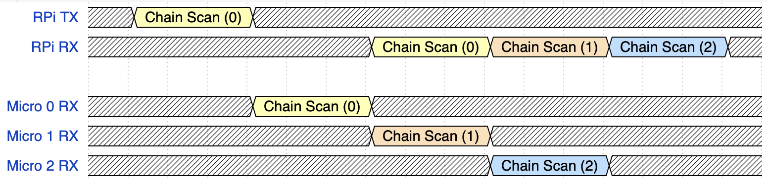
The microcontrollers don't store their IDs in flash, so there needs to be a way to assign their IDs when they boot. This is done through a special Chain Scan command, which the Raspberry Pi sends to the first microcontroller in the chain with the Micro ID byte set to 0.
Whenever a microcontroller receives a Chain Scan command, it sets its own ID to that of the command, then it increments the ID in the command and sends it to the next microcontroller in the chain. Lastly, it sends a response back to the Raspberry Pi with its new ID. At the end of a chain scan, all microcontrollers have an ID that corresponds to their position in the chain, and the Raspberry Pi gets a basic health check of the microcontrollers.
Motor Control
As mentioned above, each microcontroller is responsible for the position control of two motors. The outputs of the rotary encoders are connected directly to two timer peripherals on the microcontroller, so they get decoded without needing to involve the CPU. That way, the firmware will never miss an encoder step because the CPU is too busy.
The motor drivers have four drive modes that are selected with two GPIOs: forward, reverse, coast, and brake. We found that braking the motors when not moving them provides better position control, but the back-EMF induced by braking is far too electrically noisy, causing microcontroller brownouts and UART glitches. In the end, we only used the forward, reverse, and coast drive modes, and we were careful not to drive the motors against their direction of motion.
Because we used the only two PWM-capable timer peripherals for the encoders, we weren't able to drive the motors with PWM. Instead, the position control loop runs at 1 kHz, and we set the motor drive GPIOs in software on each iteration.
The control loop itself runs two separate PID controllers, one for when the ball is moving up, and another for when it's moving down. The dynamics of going up versus going down were different enough with the coast drive mode that one PID tuning for both didn't provide sufficient position control. Since we aren't able to use PWM to drive the motors, the output of the PID controllers is interpreted simply as:
- Greater than zero, drive the motor forward
- Less than zero, drive the motor in reverse
- Equal to zero, coast the motor
This control scheme presented some tuning challenges and tradeoffs, mostly compromising on precision. The motors have a large gear reduction, so each encoder step is tiny, only about 13.7 microns of movement of the ball. While we have very fine-grained sensor resolution, the precision is closer to 0.5mm for any arbitrary position.
Animation and Synchronization
Once per frame, the Raspberry Pi sends new target positions for each motor to all of the microcontrollers. The motors won't start moving to those new positions until the microcontrollers see a rising edge on their sync in pins, which is ultimately driven by the Raspberry Pi after it's done sending all positions.

One thing to note is that the microcontrollers pass the sync signal from one to another, instead of them all being connected directly to the Raspberry Pi. The propagation delay between SYNC_IN and SYNC_OUT is configurable in 0.1ms increments, which helps smooth out the inrush current when multiple motors are told to start moving at the same time.
Firmware Updates
The microcontrollers receive firmware updates over UART using the built-in bootloader from ST. To keep the firmware simple, instead of having every microcontroller update the next one independently, they have a UART passthrough mode so the Raspberry Pi can talk through the chain to the microcontroller that's being updated. Since they can't receive commands in passthrough mode, they'll go back to normal operation if they see a rising edge on the sync signal.
We found that firmware updates through a long chain of microcontrollers in passthrough mode weren't very stable at 230400 kbps, so there's a command that the Raspberry Pi can use to slow down the microcontrollers' baud rates to 115200.
The firmware update process for the whole chain looks like:
- Slow down every microcontroller's baud rates, starting with the last one in the chain and working backwards
- Starting with the last microcontroller, tell it to jump to the bootloader, then put all of the preceding microcontrollers into passthrough mode
- Update that microcontroller normally over UART
- Toggle the sync signal to get the microcontrollers out of passthrough mode
- Repeat steps 2 through 4, working backwards toward the front of the chain
Safety
The firmware has some safety features to help avoid collisions, brownouts, and runaway motors:
- If the firmware crashes, the HardFault handler turns off the motors
- During normal operation, target positions above zero (i.e. up into the enclosure) are thrown out
- If an encoder failure is detected, the motor is disabled (this is defined as driving the motor in one direction for 500ms without seeing the motor move past a very small threshold)
- If a brownout is imminent, the motor positions are written to flash and the motors are turned off to try to avoid the brownout
Software
All of the software running on the Raspberry Pi to control the sculpture is written in Python. The main piece of software is sculpy.py, which is where all the sculpture-level features are implemented (running animations, homing, firmware updates, etc). It exposes an RPC server, and a simple sculpy_client.py script is used to interact with it with commands like start_animating, enqueue_animation, and update_firmware.
One layer down, sculpture.py defines a Sculpture class that handles the lower-level details of interacting with the sculpture, like performing chain scans, sending animation frames, and controlling the sync signal.
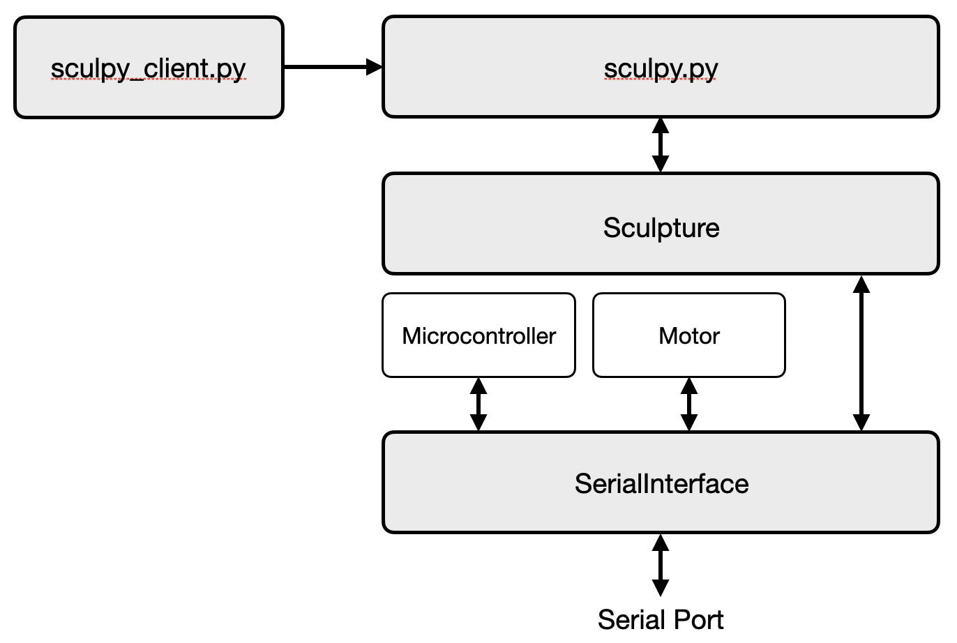
All the serial communications go through a single instance of SerialInterface, which has a write thread for encoding and sending packets, and a read thread for receiving and decoding them. Modules that use the interface call functions that simply enqueue packets for sending, or dequeue received packets. That makes developing the higher-level business logic much simpler, since Microcontroller or Motor instances also use that interface object, meaning you can write things more naturally without worrying about the details:
motors = sculpture.motors[:16]
for motor in motors:
    motor.add_position(-10000)
Configuration
Simple JSON configuration files hold details about the sculpture hardware, like the serial device path and GPIO pins. Importantly, they also define the mapping from micro and motor ID pairs to their positions in the frame, so that animations don't need know anything about how the modules are physically laid out:
{
    "host_type": "raspberry_pi",
    "sculpture_serial": "/dev/ttyAMA0",
    "sync_gpio": 23,
    "homing_gpios": [6, 13, 19, 26],
    "firmware_version": [0, 2, 9],
    "shape": [
        [[ 0, 1], [ 0, 0], [ 1, 1], [ 1, 0], [ 2, 1], [ 2, 0], [ 3, 1], [ 3, 0]],
        [[ 7, 1], [ 7, 0], [ 6, 1], [ 6, 0], [ 5, 1], [ 5, 0], [ 4, 1], [ 4, 0]],
        [[ 8, 1], [ 8, 0], [ 9, 1], [ 9, 0], [10, 1], [10, 0], [11, 1], [11, 0]],
        [[15, 1], [15, 0], [14, 1], [14, 0], [13, 1], [13, 0], [12, 1], [12, 0]],
        [[16, 1], [16, 0], [17, 1], [17, 0], [18, 1], [18, 0], [19, 1], [19, 0]],
        [[23, 1], [23, 0], [22, 1], [22, 0], [21, 1], [21, 0], [20, 1], [20, 0]],
        [[24, 1], [24, 0], [25, 1], [25, 0], [26, 1], [26, 0], [27, 1], [27, 0]],
        [[31, 1], [31, 0], [30, 1], [30, 0], [29, 1], [29, 0], [28, 1], [28, 0]],
        [[32, 1], [32, 0], [33, 1], [33, 0], [34, 1], [34, 0], [35, 1], [35, 0]],
        [[39, 1], [39, 0], [38, 1], [38, 0], [37, 1], [37, 0], [36, 1], [36, 0]]
    ]
}
A similar mapping is used for the lights on the bottom of the enclosure, it's just a little gnarlier to account for the gaps between LEDs.
Animations
The animations and patterns are written in separate Python files, using a shader-like API to specify ball positions. The API boils down to answering the question: where should the balls be at this time in the animation? Then the animation manager in sculpy.py just asks that question 20 times per second and sends the answers to the motors.
This adds a bit of complexity to writing animations, but it lets sculpy.py maintain control over the sculpture. The animations can be interrupted and checked, and they don't need a Sculpture or SerialInterface instance.
We also wrote up a sculpture simulator, which helped a ton with writing animations and testing changes to sculpy.py. It's implemented with a special Sculpture subclass so that all the same code and animations that run on the real sculpture can be used without change.
If you want to write your own animations or see some examples, there's a lightweight simulator on GitHub you can use for just that purpose!

Homing
For automatic homing, each ball has a limit switch above it on the bottom of the enclosure. The switches are all connected in parallel to reduce the number of GPIOs needed, so only one ball from each homing plate can be homed at once.
To home a ball, it's slowly raised until it hits the limit switch, and then it's lowered back down even more slowly until the limit switch opens again. Then, the ball is lowered a known amount to provide a bit of a buffer, and that position is considered zero.
For now, it only homes one ball at a time, but in the future we could speed this up a bit by homing four balls at once, one from each homing plate.
The homing switches also provide a nice safety feature: if a switch gets hit at any time while animating, the Raspberry Pi will tell all the microcontrollers to turn off their motors immediately. This actually saved our skin once!
Tooling
We wrote some software tooling early on that became crucial later in the project, it was well worth the time investment. Most of them were just one-off scripts to test some new feature or debug an issue, but some of them were useful enough to stick around. The one that we use the most is aptly named hacky_homer.py, which lets us manually move each ball up and down and set its home position without running the full homing procedure.
The most useful script for testing and debugging was one of the first ones, commander.py. It provides a basic CLI for sending individual messages over serial, and it prints out any messages that it receives:
$ python3 commander.py /dev/ttyAMA0
[sculpture]$ get_status 3 0
<- Sending Get Status Command
<-      micro_id: 3
<-    message_id: MessageId.GET_STATUS (3)
<-  message_type: MessageType.COMMAND (0)
<-      motor_id: 0

-> Received Get Status Response
->      micro_id: 3
->    message_id: MessageId.GET_STATUS (3)
->  message_type: MessageType.RESPONSE (1)
->      motor_id: 0
->        status: 3
->                SystemStatusFlag.MOTOR_0_HOMED
->                SystemStatusFlag.MOTOR_1_HOMED
->          mode: SystemMode.IDLE (0)
There are some other scripts, notably tuner.py for interactively tuning the PID controllers. Additionally, sculpy.py has some quality-of-life convenience commands like go_home and rescan_chain that can help get the sculpture back into a good state without needing a power cycle.
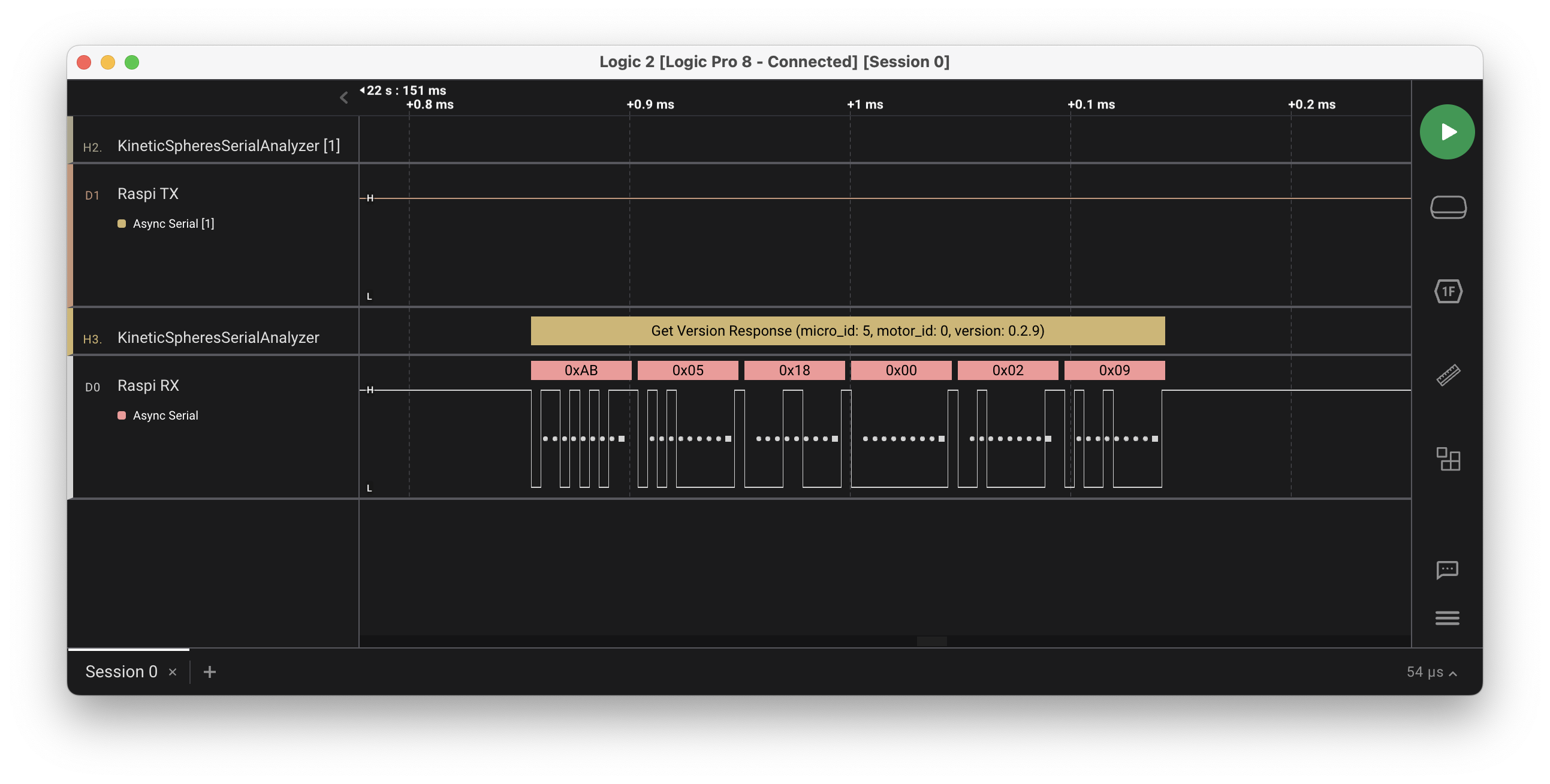
Besides scripts and commands, a custom Saleae Logic analyzer was a huge lifesaver. While the convenience of decoding packets for us right there on the trace was helpful, its real value was in debugging weird communications issues. We were able to use it to export tables of packets from long-running traces, which we could feed to Python scripts to pinpoint dropped or corrupted packets.
Challenges
While we thankfully never needed to go back and make big changes to the hardware or overall architecture of the sculpture, we did run into some scaling and integration issues along the way. Here are some of the notable ones:
- The inrush current of the motors was much harder on our power supplies than expected, causing brownouts and communication failures, so we had to increase the number of supplies from 2 to 5 and add a ton of capacitance to the boards.
- The initial implementation of the UART protocol wasn't particularly robust or performant (e.g. there was no error handling on the firmware side), which wasn't an issue until there was more than a handful of microcontrollers talking back and forth at once. We had to add some features to the protocol (like the delimiter byte) and do a lot of profiling and optimization on the firmware side to avoid dropping packets. This is one of the areas where having a more powerful microcontroller would have been helpful.
- We started to see some odd hardware failures after we installed all of the modules and got to testing the array in earnest. They typically were marginal issues that would only manifest after a bit of time, like a cold solder joint cracking. Basically, we were on the first part of the bathtub curve, and it made for a frustrating week of swapping out and fixing modules, boards, and components. But, things got much more stable after that!
- We didn't have very easy access to the modules after they were all installed. For instance, we'd have to pull a module out to access the SWD port if we had to recover a microcontroller. This led to more handling of the modules and boards, which led to its own series of issues. One of the most common problems when reinstalling a module was reconnecting the 7-pin cables incorrectly. They can be flipped 180 degrees without a problem, but we fried a couple boards by plugging them in offset by one pin. Next time, we'll use keyed connectors!
Future Improvements
There are some features we're thinking about adding to the sculpture, like some sort of interactivity, or a way to pull in and display weather or other data. If we make a second kinetic sculpture, there are lots of things we'd like to change or improve, especially if cost wasn't a consideration! The list includes:
- A more performant microcontroller, and more robust communications to go along with that
- Brushless motors with more precise position control (quieter and more powerful!)
- A way for each microcontroller to reset or power cycle the next one, so we could always recover the chain without physical intervention
- Get the boards made professionally instead of manually assembling them (to reduce those initial hardware failures)
- A bigger grid? Maybe even a hexagonal grid?