 Omar Khorshid
System Architecture
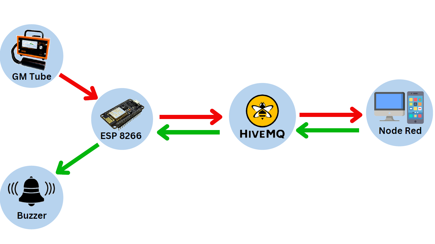
The high-level architecture diagram illustrates the various components and their interactions within the IoT Radiation Monitor system. It showcases the integration of radiation sensors, IoT devices, cloud infrastructure (HiveMQ), and user interfaces (Node Red).
The Radiation sensor (Geiger Muller tube) and the Buzzer are connected through the GPIO pins of the ESP8266 Node MCU board. ESP8266 calculates the radiation levels from the sensor and compares it to the threshold to decide whether or not to sound the alarm. The data of the radiation dose rate and the total absorbed dose is sent (Published) to the MQTT broker (Hive MQ) in separate messages for each on separate topics. Node-Red interface receives both of the readings and displays them as well as sends the updated threshold to the broker.
Hardware Components
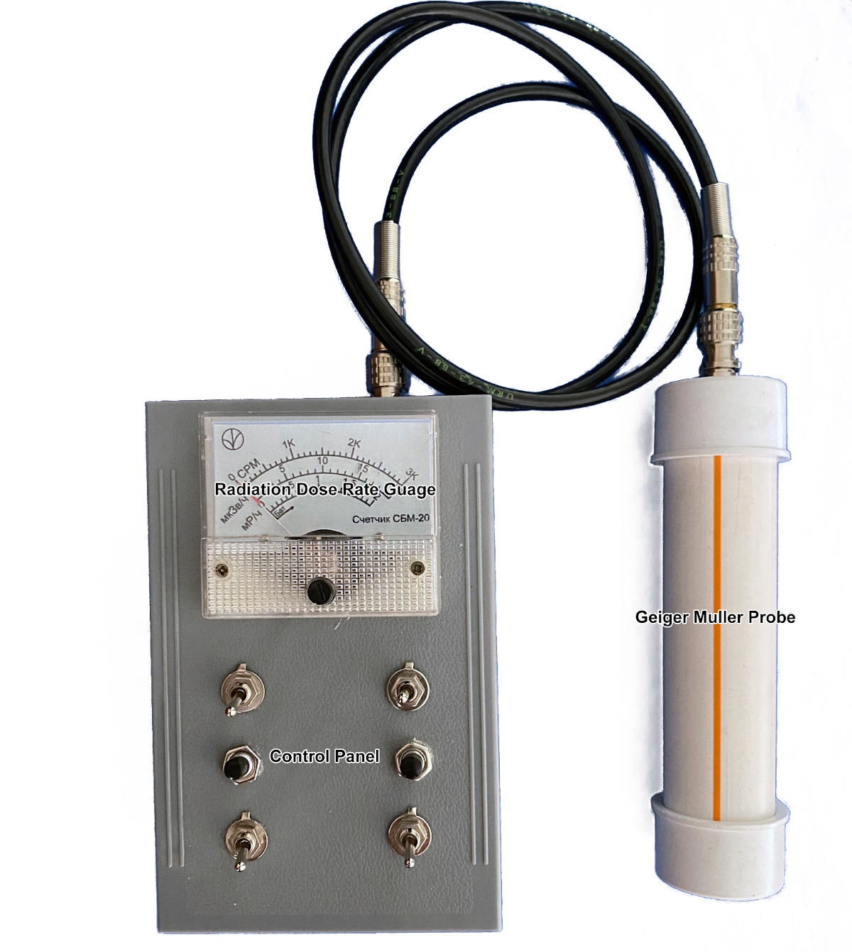
To measure and detect radiation particles (Gamma and Hard Beta particles), the device uses a Geiger Muller tube. Geiger-Muller tubes, also known as GM tubes, are radiation detectors that operate on the principle of gas ionization. Within the tube, there is a gas-filled chamber containing a high-voltage electrode, typically a wire, surrounded by a metal cylinder. When ionizing radiation, such as alpha or beta particles, or gamma rays, enters the tube, it collides with gas atoms, knocking off electrons and creating positive ions. The high voltage applied to the electrode creates an electric field that accelerates the free electrons toward the cylinder, causing further ionization along their path. This multiplication effect, known as the Townsend avalanche, creates a detectable electrical pulse. The pulse is amplified and counted to determine the intensity of radiation. The GM tube's design and operation make it highly sensitive and capable of detecting even small amounts of radiation.
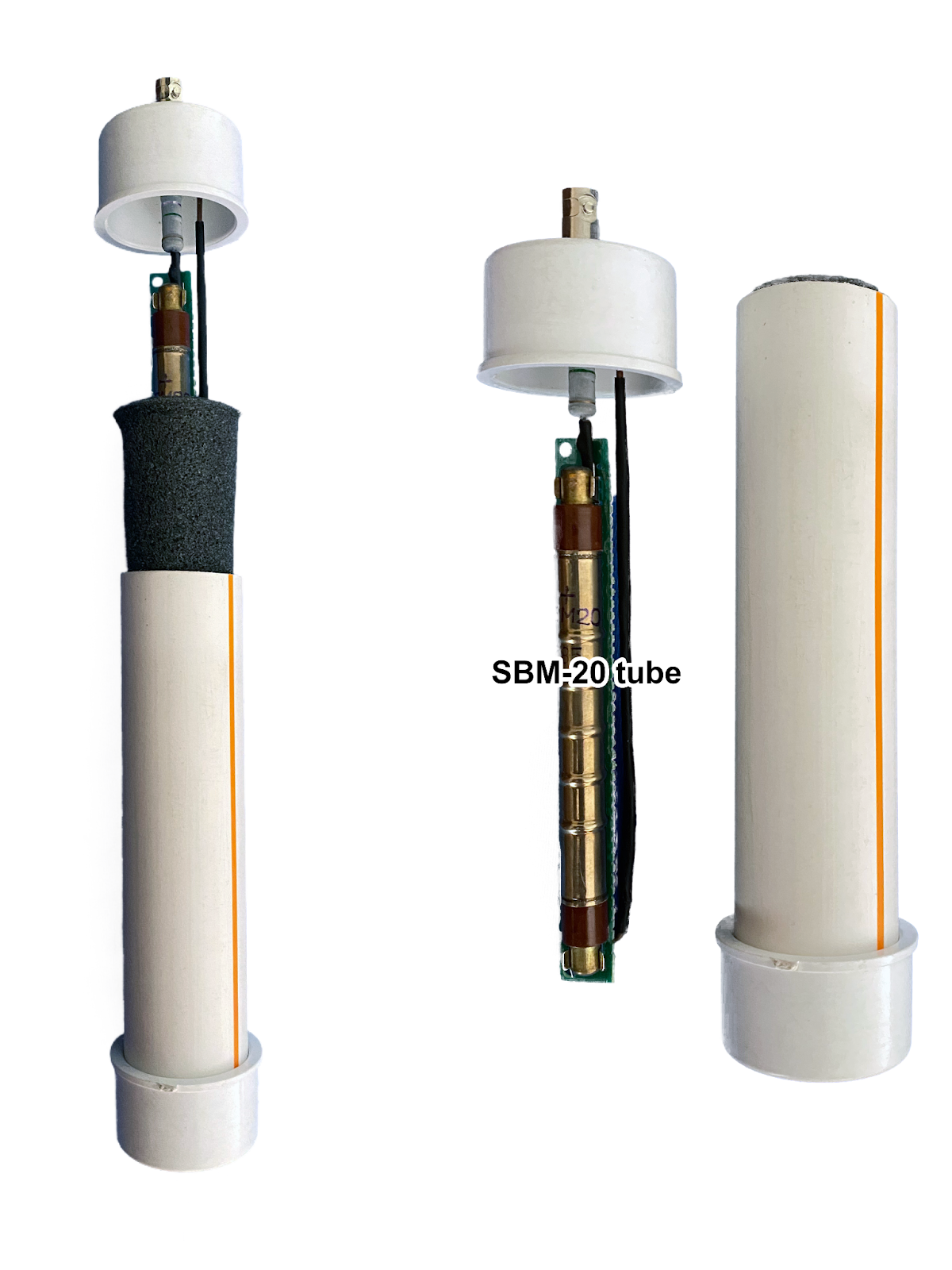
The GM tube used in this project is SBM-20 tube. The SBM-20 tube is a specific type of Geiger-Muller tube widely used for radiation detection and measurement. It features a cylindrical design with a central anode wire surrounded by a cathode cylinder, both enclosed within a gas-filled chamber. The SBM-20 tube is primarily sensitive to beta and gamma radiation and has a relatively low threshold for detecting radiation. It operates at a recommended voltage of around 400-500 volts. The SBM-20 tube is known for its compact size and ease of use, making it popular among hobbyists, educators, and professionals alike. It provides a reliable and cost-effective solution for various applications, including environmental monitoring, radiological research, and educational demonstrations.

A stable high voltage (400v DC) is required for the GM tube operation.
To generate the necessary high voltage (400v DC) for the GM tube, a boost converter circuit is implemented as follows:
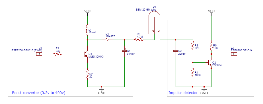
The boost converter circuit above works as follows:
A boost converter is a type of DC-DC converter that steps up the input voltage to a higher output voltage. When a PWM (Pulse Width Modulation) signal is utilized from a microcontroller without feedback, the boost converter operates based on a fixed duty cycle. The working principle of such a boost converter can be outlined as follows:
- The microcontroller generates a PWM signal with a fixed duty cycle, which determines the ON and OFF times of the switching transistor within the boost converter.
- During the ON time, the switching transistor is turned ON, allowing current to flow from the input voltage source through the inductor.
- As the current flows through the inductor, energy is stored in its magnetic field, and the voltage across the inductor increases.
- During the OFF time, the switching transistor is turned OFF, interrupting the flow of current from the input source.
- The inductor's stored energy seeks a path to discharge, and as a result, the diode connected across the load becomes...


 mircemk
 Jenny List
please add to radioactive@home