Finally, I had some time (and friends) to investigate what's happening with current sensing.
In Part 1, I made four interesting observations, but only deserves a response: Yes, it's normal for the voltage on the current shunt to be non-zero. (At least, that's what I was told) This is still problematic and has to be investigate further.
This time, I've altered the way the H-bridge is controlled, conducted additional measurements, and added even more measurements on top of those.
Switching mode
Let's summarize how the H-bridge controlled the motor: it drives the motor based on two digital input pins. The specifics vary with each H-bridge; what we used was:
- 01 input drives the motor in one direction.
- 10 input drives the motor in the opposite direction.
- 00 input is used when the motor should be idle.
I realized he might be onto something, as this is exactly what the datasheet recommends. Why? In 00 mode, the motor pins are not connected to anything. In 11 mode, the motor pins are shorted together.
To achieve gradual control, we use PWM. With a 25% duty cycle, we spend 25% of the time in the 10 state and 75% of the time in the 00 state.
A friend of mine, J. Mrazek (thanks!), suggested that this was not optimal and that I should switch between the 10 and 11 states instead. That is, one more option:
4. 11 input when the motor should not be idle.
After reviewing the datasheet of the DRV8251A, I realized he might be onto something, as this is exactly what the datasheet recommends. Why? In 00 mode, the motor pins are not connected to anything. In 11 mode, the motor pins are shorted together.
I won't detail all the consequences, as I'm not certain about them, but there is one practical aspect I can work with: in 11 mode, I can measure the current flowing through the motor (thanks to the internal current sensing of the H-bridge).
The way I see it, switching between 01 and 11 modes allows the 01 mode to let the current flow into the motor, while the 11 mode shows how it circulates inside—both providing good insight into the torque applied by the motor, which is the real value I'm interested in.
Current readings with H-bridge in 01/11 mode
Let’s measure all the data again! We'll use the same table as in Part 1, so please refer there for an explanation.
| power | 0% | 25% | 50% | 75% | 100% |
| power source current | 14mA | 45mA | 83mA | 130mA | 170mA |
| R7 voltage | 25mV | 172mV | 210mV | 245mV | 267mV |
| calculated motor current | 15mA | 109mA | 131mA | 156mA | 169mA |
This time, the data table showed anomalies; the voltage on pin R7 no longer scaled linearly with the PWM duty cycle, which was baffling. This issue perplexed me for a while, and I was on the verge of discarding the H-bridge as this seemed bonkers.
In an attempt to understand what was happening, I also captured a screenshot of the voltage profile to observe how the voltage on R7 changed during the duration of one pulse.
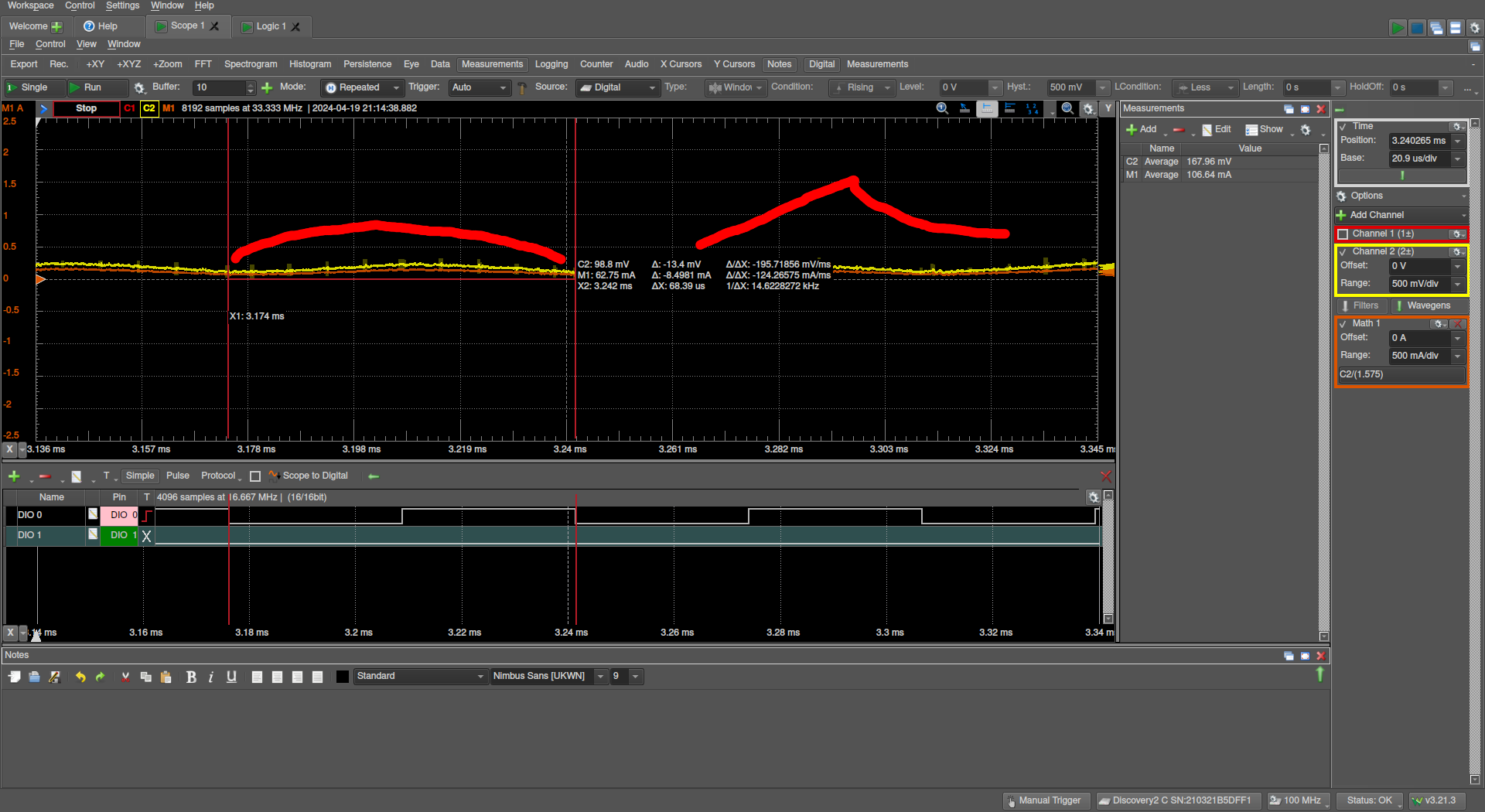
As my modest drawing skills illustrate, the new measurements reveal significant changes in the voltage profile. The large red shape on the left, representing the current state, shows a symmetric rise and fall in voltage. On the right side, you can see the profile from previous measurements (using 01/00 mode). The difference is striking: in 11 mode, the voltage on R7 decreases much more slowly than in 00 mode, resulting in higher measured current per period.
The central question remains: why has the current stopped behaving linearly?
I understand that the PWM duty cycle and current might not scale linearly, but the non-linearty is too big.
Current readings with H-Bridge in 01/11 mode + current probe on scope + different power source
We managed to borrow a high-quality current sensing probe from a friend—far more expensive than I'd typically invest in hobby equipment. With this, we were able to measure the current flowing through the motor. Unfortunately, I didn't take any pictures of the experiment, so there are no images to share this time.
| power | 0% | 25% | 50% | 75% | 100% |
| power source current | 0.01A | 0.05A | 0.09A | 0.13A | 0.18A |
| R7 voltage | 20mV | 190mV | 232mV | 262mV | 290mV |
| current probe | 0 A | 80mA | 100mA | 108mA | 115mA |
Note that the current probe showed 0A at 0% duty cycle simply because we calibrated it this way. Nevertheless, it's clear that what I observed on R7 isn’t as nonsensical as it initially seemed; in fact, it accurately reflects reality. The current flowing through the motor does not scale linearly with the PWM duty cycle—or does it
Thanks goes to J.M. who realized what is going on: physics
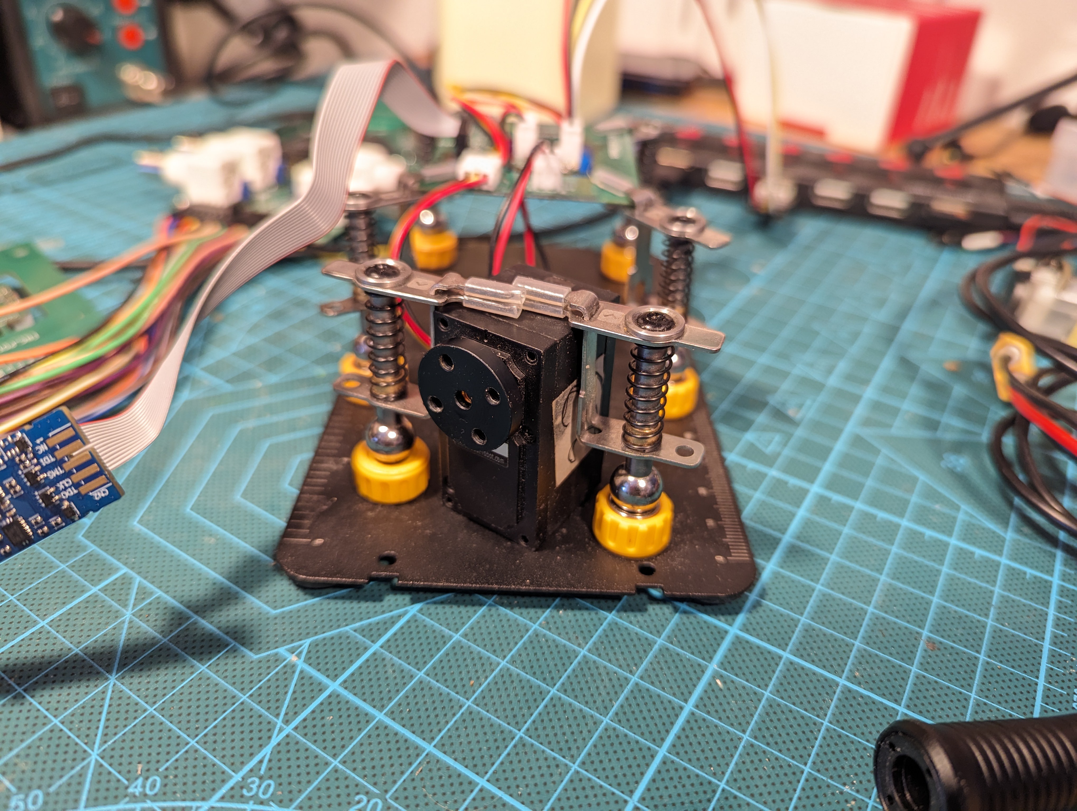
As you can see, in my setup, the motor is free-spinning—there is no load opposing the rotation. The motor has a natural limit of rotational velocity based on voltage. Typically, free-spinning motors easily reach their maximum velocity.
This is precisely what occurs in my measurements: the current flowing through the motor does not scale linearly with the duty cycle because the servo motor achieves its maximum velocity too easily, using only a small amount of current. Once it reaches this velocity, no additional current is drawn, regardless of increases in the duty cycle.
How can we be sure? Well, J.M. had a brilliant idea to test this. We took a small DC motor and fixed its shaft so it couldn’t move. Sure enough, with this setup, we observed that the current scales linearly with the duty cycle. (Of course, I didn't take screenshots of this data either).
Conclusion? Current sensing works! \o/ (kinda)
Takeaway
Although we confirmed that everything functions well, there are some crucial observations I need to consider for future work.
First and foremost—running the servo motor free-spinning is tricky. It doesn’t mean that things won’t work, but one must be aware of the consequences, especially when current sensing is involved. I believe the servo should perform well without load, but I don’t think I want to develop it in a free-spinning state. It might be easier to start with some load on the motor to ensure everything functions correctly, and then later address the free-spinning scenario as a specific case.
Secondly, during the numerous measurements we made that night, we realized one thing: the current sensing is extremely sensitive, meaning it picks up every electrical disturbance. Whether it’s because the system is inherently noisy, or because we use brushed motors where I can detect the brushes passing by on the spinning axis, none of these factors simplify the task for the PID controller.
We discussed this issue, and I plan to explore how to increase the load on the motor and possibly add a filter to the current sensing to prevent the PID controller from being overwhelmed by these disturbances.
Discussions
Become a Hackaday.io Member
Create an account to leave a comment. Already have an account? Log In.